Project Development
A brand new base
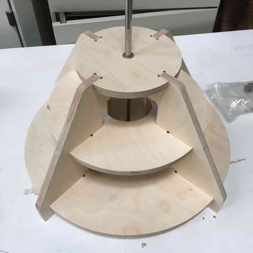
I have been slowly improving the design of my turbine of the course of FabAcademy, and settled on an inverted cone shaped base. Such a design provides more stability to support fast rotating axis better with four points of contact (legs) pressfitted together into three layers.
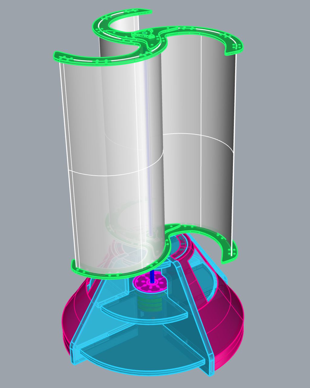
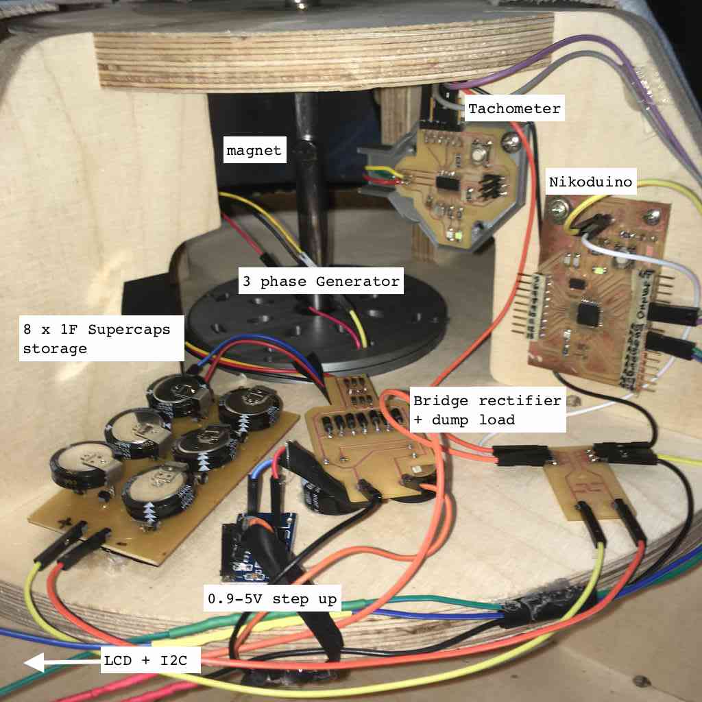
Only the top and the bottom shelves act as points of rotation using the same brass flange sleeve bearings that are fitted snugly into the wood. The purpose of the middle shelf is to house the electronics - rectifier, dump load, step-up and battery/capacitors) that will be powered by my 3 phase direct-drive generator.
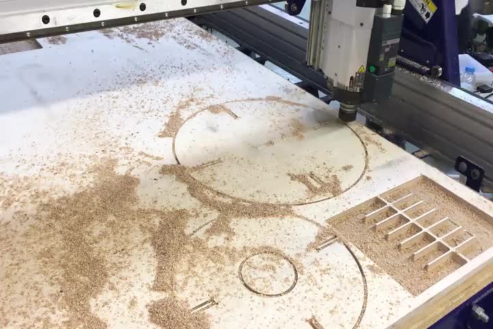
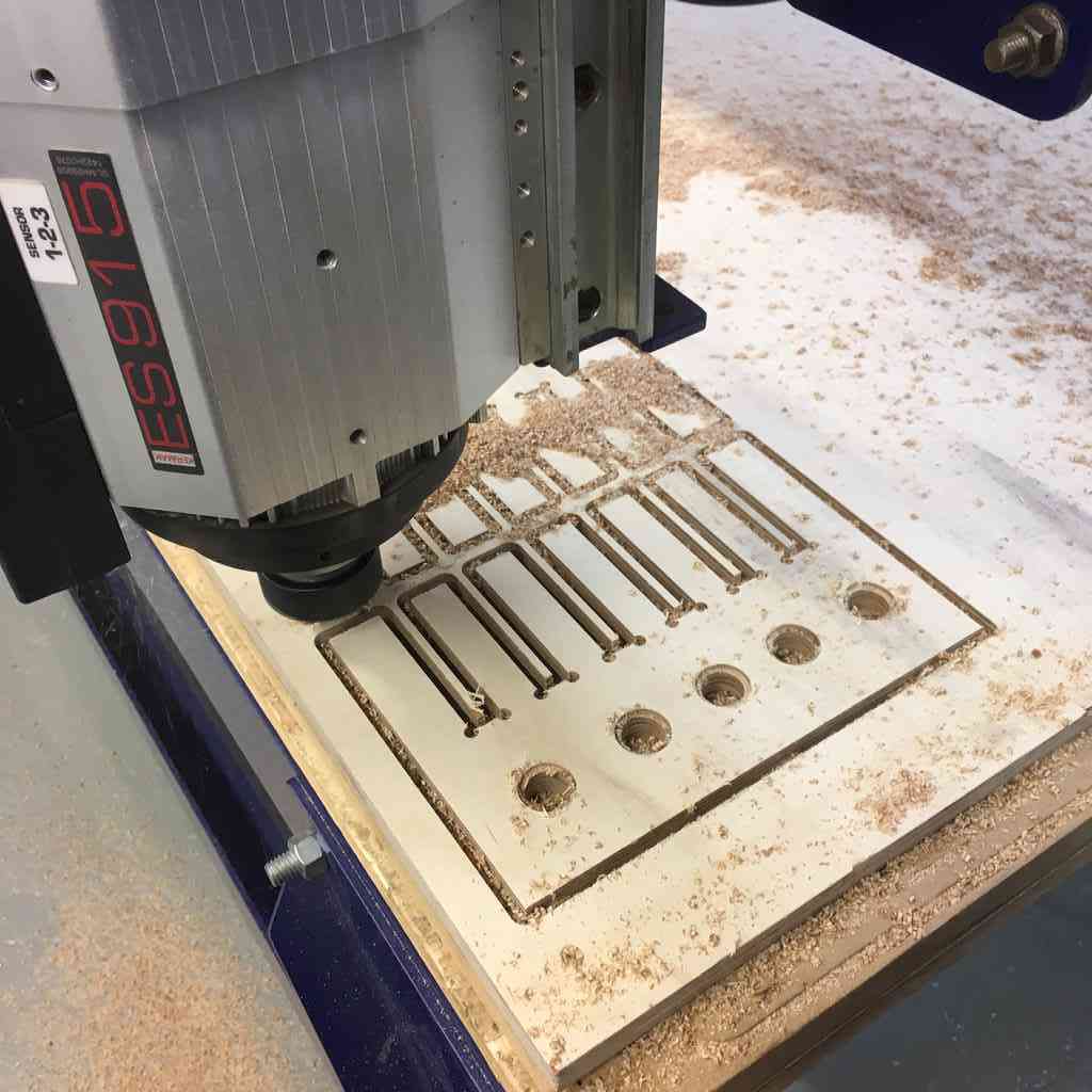
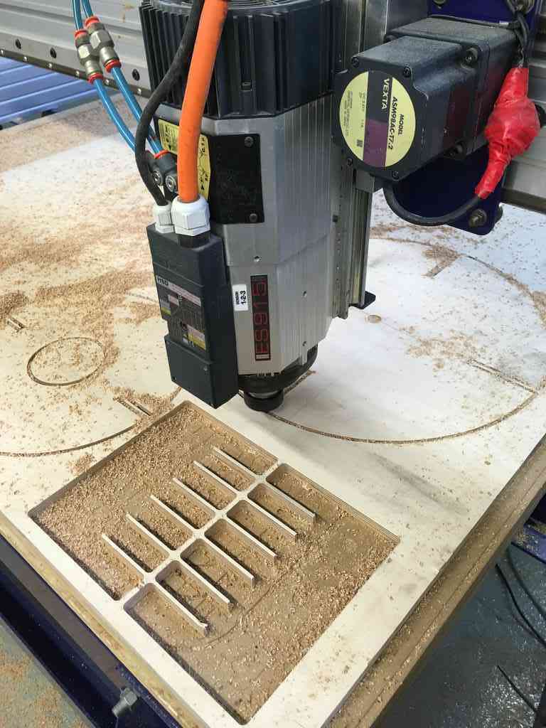
I milled the base using our lab ShopBot using some 15 mm (nice) plywood off-cuts they were using to make shelves.
 |
 |
Composite armour
I wanted to try and layer some see-through plastic we had in the lab to create a window in my composite which would serve to observe the inner workings of the generator, tachometer and other electronics.
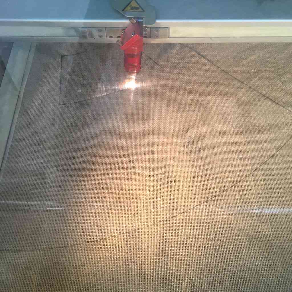
For this I needed to laser cut the burlap to make sure I got exactly equal size layers. For the the lasercutter I used the Trotec 400, testing the fabric settings with a low frequency and power and slowly increasing the power. This is a highly flammable material so I wen’t carefully at first making sure I didn’t get any flames. Finally, I found my optimal settings at:
Power = 40
Speed = 1.00
PPI/Hz = 1000
 |
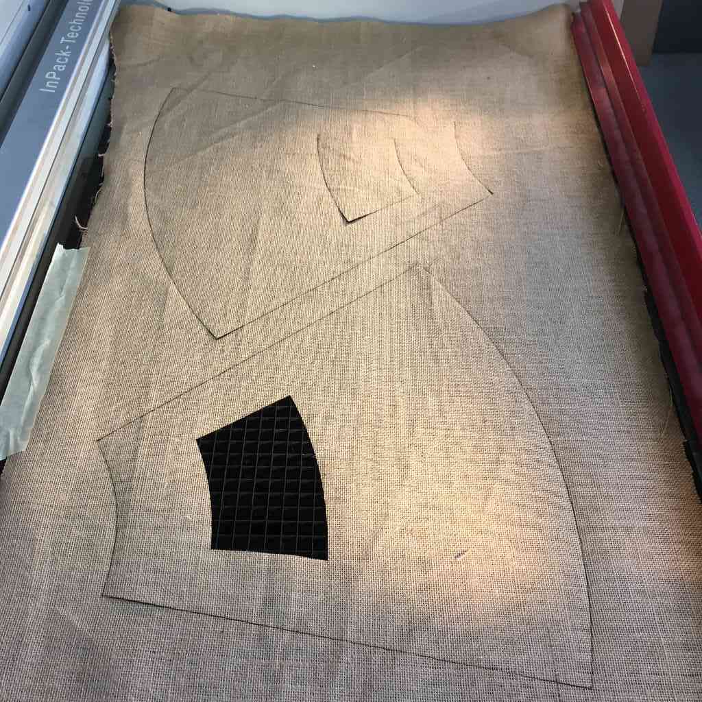 |
I took the extra effort of using the manual sewing machine in the FabTextile room to sew one side/seam of the two burlap layers together. This helped make sure that the layers remained aligned when I added the epoxy and the rigid plastic in the middle.
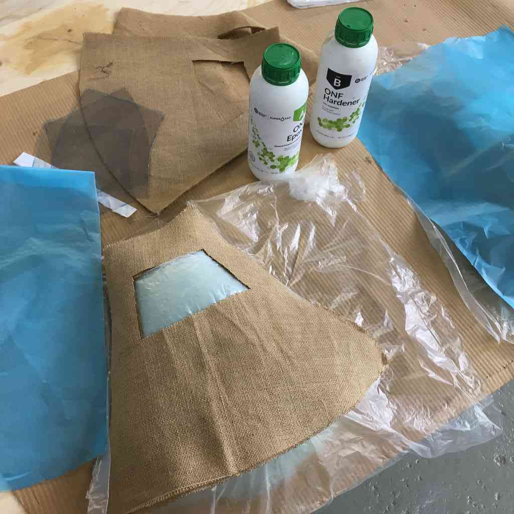
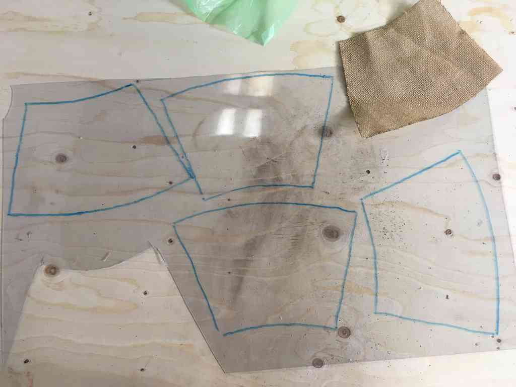
Below, I used the negative of the widow (with a 20mm offset) which I lasercut in the burlap to trace manually onto the plastic sheeting and cut it out by hand. I was not sure the exact properties of this material (nor did anyone else) and had a faint suspicion it could be a PVC derivate which risks not only ruining the laser optics, but also emits a noxious chlorine gas when cut! Also sometimes hands and scissors is just simpler, quicker and easier.
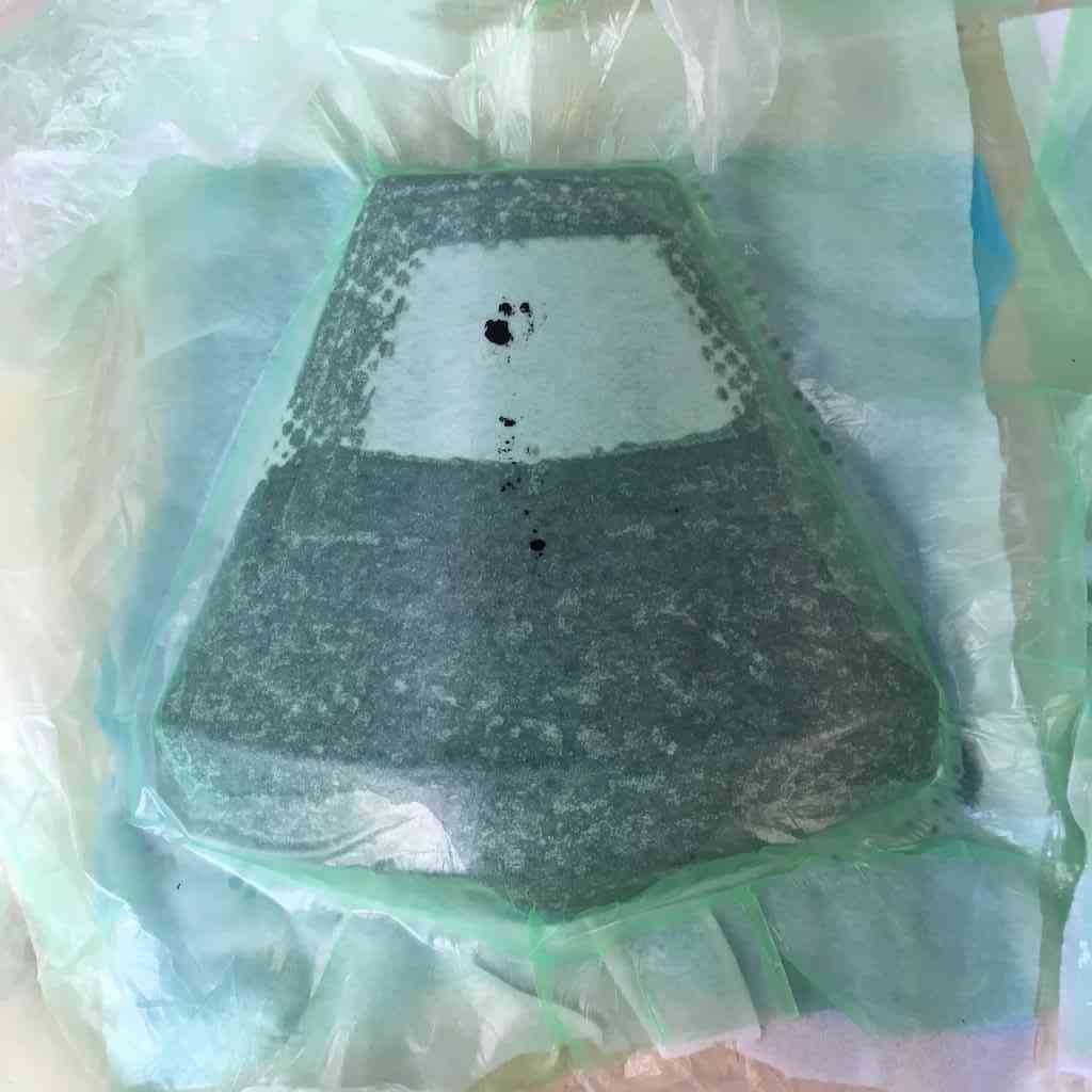
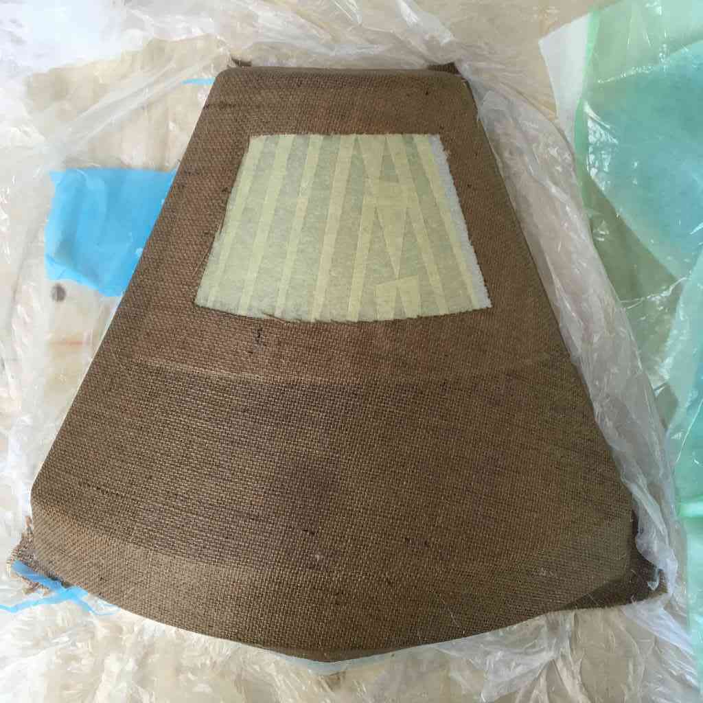
Before layering the sticky epoxy, I used masking tape to cover the plastic so that the resin doesn’t smudge and stick to the plastic under the vacuum. Once it is dry you just have to peel it off. After leaving it overnight to cure in the vacuum machine, here are the results:
 |
 |
And a good knocking test for good measure:
Cutting and mounting my wings
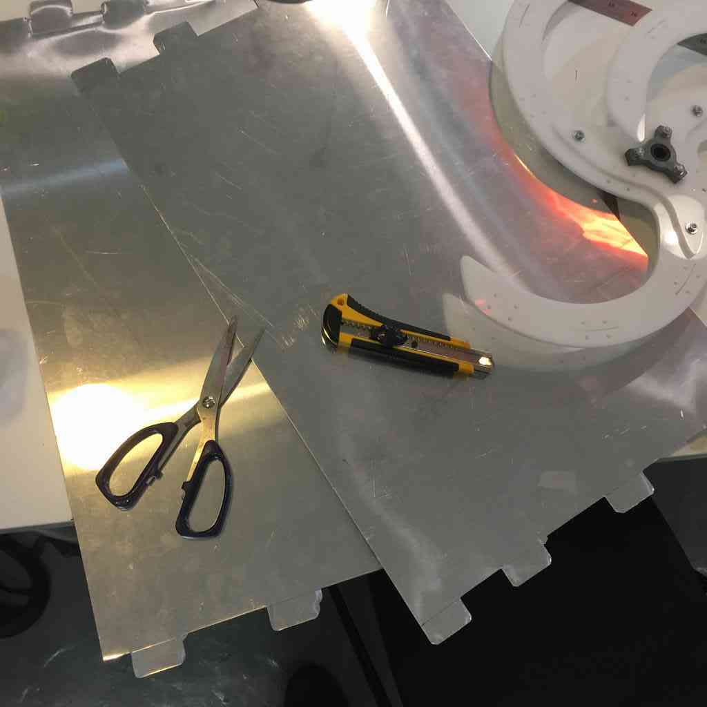
As you may have noticed, I decided on 0.5 mm aluminium flashing to use as my wings. For my prototype I used a cheaper polypropylene which worked fine but did not seem very durable. Aluminium is relatively cheap and malleable to work with. Although this flashing is very reflective, I was thinking that I may be able to laser cut it by somehow covering the surface with masking tape.
I did some tiny tests with this in the Trotec and it barely left a scratch. While I probably could have used the ShopBot, I was very pressed for time so I decided on manually cuttin out my wings. First, I made sure I had the precise measurements.
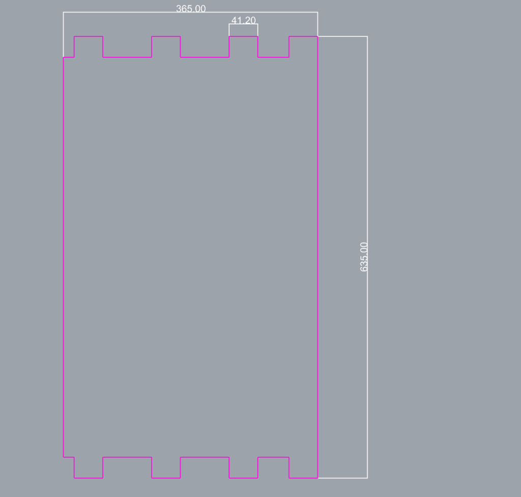 |
 |
Then using a cutter, ruler and scissors for the tricky corners I cut my wings. Although this was a very analogue method, aluminium is very easy to work with.
 |
 |
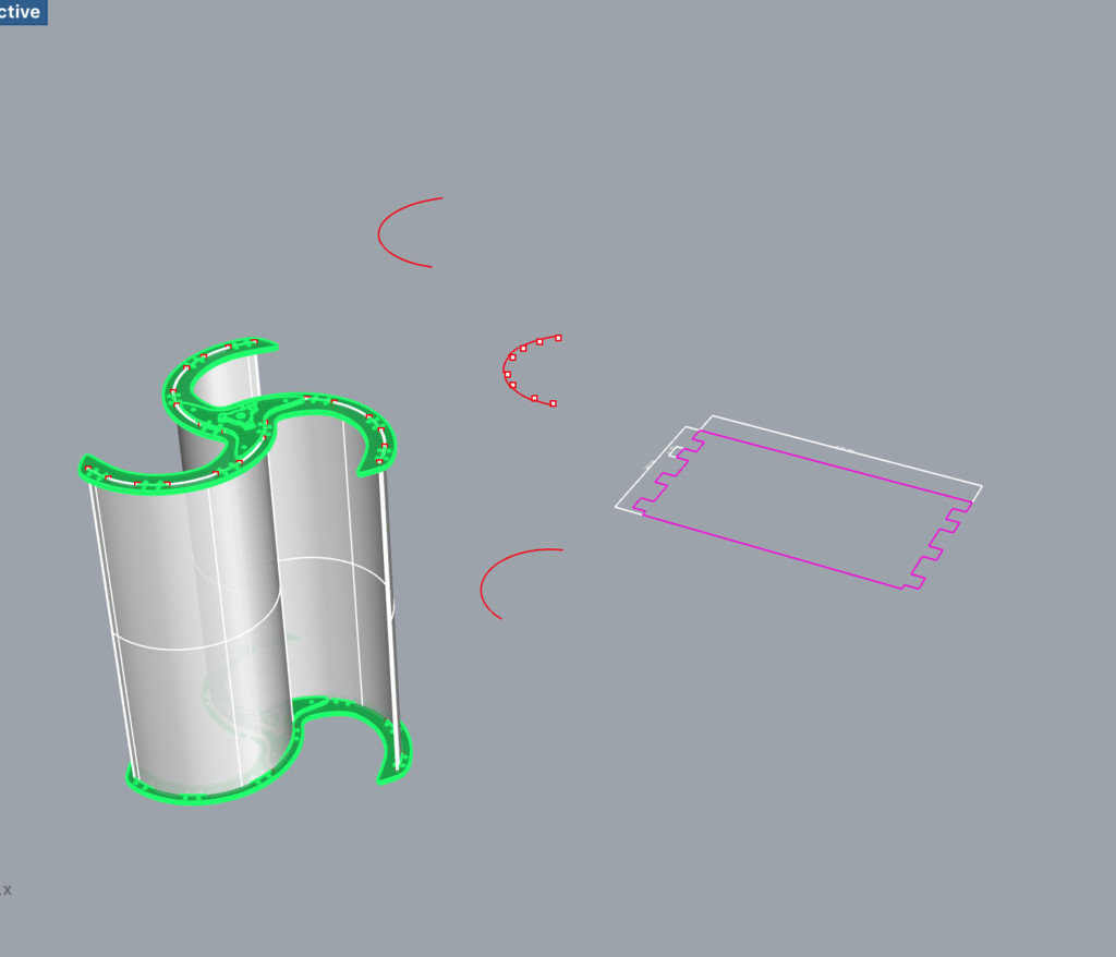
Mounting
Mounting the wings into both wing vanes was more complicated than I had anticipated. First I had to make sure the generator was mounted with radial bearings onto the axis and the top “shelf” of my base with sleeve bearing - which directs the shaft - already in place before fitting the bottom acrylic wing support. That in place I could mount the axis and gennie onto the base, and slowly fit the wings into the bottom vane support one by one. Thanks a bunch to Matteo for giving me an extra hand here.
Getting the top wing vanes aligned and mounted was equally challenging. With the polypropylene I had the advantage of being able to bend the material to get the teeth into the slots. Not so with aluminium. This meant that the each tooth of each wing had to fit in more or less simultaneously. Not sure now, but we managed :)
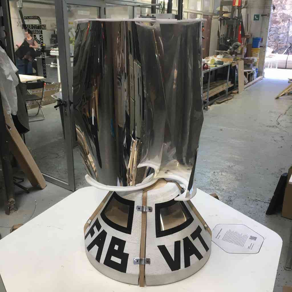
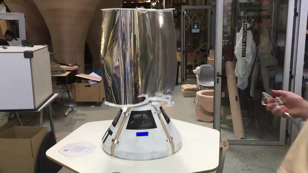
Here she is all assembled:
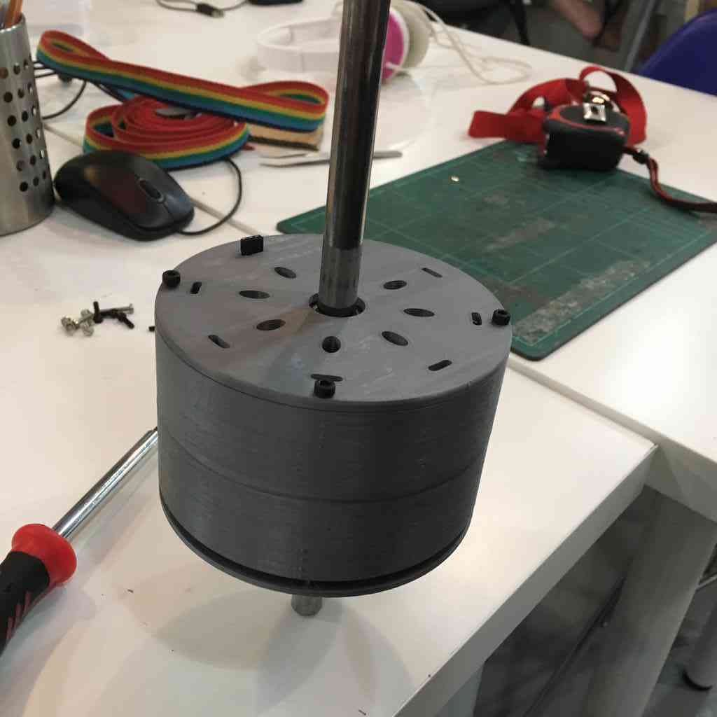
Connecting generator and electronics
Before mounting the composite shell, I was testing the various electronic components and how to best integrate them. This is my first attempt, and although the final is much less messy and more organised, I also fastened the rectifier and supercaps to the bottom shelf so that they are stable. But arrangement is more or less the same, so I label them below so for sake of demonstration:
And ready for blast off!