Wk3. Computer Aided Design
Assignment: Model (raster, vector, 2D, 3D, render, animate, simulate, …) a possible final project, and post it on your class page.
Genesis
The genesis of Computer Aided Design or CAD software started with Sketchpad, a revolutionary computer program written by Ivan Sutherland in 1963 for his PhD thesis at MIT. His supervisor was Claude Shannon who we met in week 1.
Sketchpad was the first program ever to use a complete graphical user interface aka GUI. Sutherland is sort of the Yoda of CAD design software. He not only made playing with computers sexy, artistic and fun, but also pioneered the concept of object oriented programming. For all of you virtual reality enthusiasts, he was well ahead of the Matrix. He says:
The ultimate display would, of course, be a room within which the computer can control the existence of matter. A chair displayed in such a room would be good enough to sit in. Handcuffs displayed in such a room would be confining, and a bullet displayed in such a room would be fatal.”
Here’s a great demo of Sutherland working Sketchpad back when to run such a program you needed a computer the size of an elephant. This computer was the TX2, a 38-bit word machine with a 68Kword main memory, complete with light pen, switches and a 9 inch 1024 x 1024 pixel screen. The TX2 is like the homo habilis of modern computers. But thats another story.
But lets go back to basics. What is Compute Animated Design and how does it work?
2D Design
- Drawing in a notebook
- Using a graphics editor
Raster Graphics:
A raster graphics or bitmap image processor uses a dot matrix data structure, representing a generally rectangular grid of pixels, or points of colour, viewable via a monitor, or other display medium. I have used photoshop quite a bit but decided to try out GIMP as a 2D bitmap editing program. Here is me pushing pixels in Gimp:
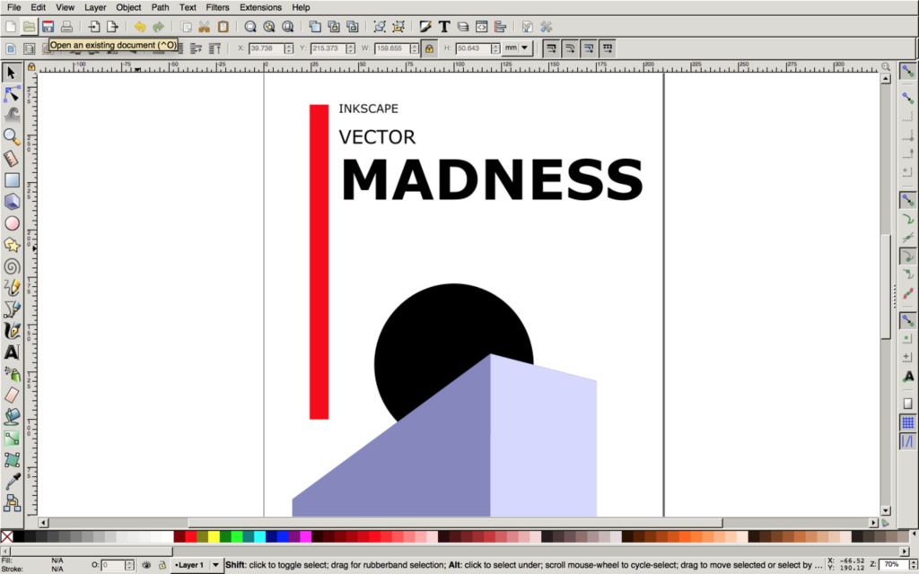
Vector Graphics:
Vectors represent an image using vectors and not pixels. Inkscape, Illustrator and FreeCad are all vector graphic tools. Here I decided to give Inkscape a try out. I actually found it far more powerful and versatile that I expected. Inkscape also has lots of plugins for box press-fits and other stuff, and being open source has a very helpful community and resources.
3D Design
Three dimensional CAD software usually incorporates a variety of functionality to design, render and manipulate complex geometry. These are as follows:
-
Constructive solid geometry is logic applied to shapes, the idea that you can add, subtract or intersect shapes to and from each other using Boolean operators. In more advanced design tools, it remembers the history of your original shapes so if you go back and change it, it will affect the final geometry.
-
Constrained 3D design allows for constraints to be applied between geometry such as collinearity, perpendicularity, tangency, symmetry, coincidency and parallelity among other ways of establishing the orientation and relations between objects.
-
Hierarchy means that if you have multiple equal size holes and you want to change the diameter, you can just change one and it will modify them all.
-
Parametric Design allows for relationships between objects to be used to manipulate and inform the design of complex geometry and structures. By changing one parameter you can change the overall outcome. So as by the above example, by changing all the hole diameters, this can allow the length or width of the hole surface to change in relation.
-
Procedural modelling and algorithmic design means that you don’t just manipulate geometry on an visual interface by click and dragging but you write algorithms that manipulate the data of that geometry.
Mesh vs Nurbs
There is a lot of confusion around Mesh and Nurbs modelling. Although both can represent complex 3D objects as a computer model, they do it in completely different ways.
A mesh is a collection of vertices, edges, and faces that describe the shape of a 3D object. Often Meshes represents 3D surfaces as a series of discreet facets, much the same way as pixels represent an image with a series of coloured points. If the facets or pixels are small enough, the image appears “smooth”. Yet, if we zoom in it can appear pixelated and no longer smooth and continuous.
This is an example of a mesh model:

NURBS or Non-Uniform Rational Basis Spline surfaces are mathematical representations of curves and surfaces. They are capable of representing complex free form surfaces that are inherently smooth, and they keep their smooth shape when editing. There is no pixelization or granularity as with a mesh, adding greater precision to a model. Here is an example of a Nurbs surface, where you can see the shape of the surface is determined by control points.

A good analogy of Mesh vs Nurbs is sort of like Raster vs Vector (Photoshop vs Illustrator/Gimp vs Inkscape), one is not better than the other, they are generally used for different purposes. Some definitions to refresh your geometric memory:
- A vertex is a single point. (The plural of vertex is “vertices”)
- An edge is a straight line segment connecting two vertices.
- A face is a flat surface enclosed by edges. (Some applications call these “polygons”)
Chewing the CAD
Choosing a CAD program is like dating, there is no one right answer, people like different people, so try different tools and see what works for you.” Neil
Some notes from my CAD love diary:
Blender
Blender is a powerful, free and open source 3D creation software. It supports 3D modelling, rigging, animation, simulation, rendering, compositing and motion tracking, even video editing and game creation.
Blender is based on meshes and can change the shape of basic geometry, and animate almost anything. While it is great for photorealistic rendering, creating organic models and simulations, it’s sometimes not the ideal tool for designing precise parametric models or mechanical parts. It definitely has many advantages. It’s free and open source, community driven, has ample learning resources and is capable of most things commercial CAD softwares can do.
It’s extra versatile if you’re into scripting as you can use Python to enhance object creation, rendering and managing repetitive tasks. It’s downsides are that it is not inherently parametric and it runs on geometrical meshes which are complicated to turn into Nurbs. Blender does support designing in Nurbs but it’s a bit of a side show. While it can export to all the necessary file formats, this may hamper CAD workflow.
For Fab Academy purposes, unless you’re already a Blender coding ninja, it seems a little overkill with all it’s simulation, animation or sculpting. Also I find Blender has a crowded and complex interface for beginners, which can make a steep learning curve. But to all their own. Some swear by the Blender and I can see why.
FreeCAD
FreeCAD is a free and open source parametric 3D modeller made primarily to design real-life objects of any size. It allows you to easily modify your design by going back into your model history and change parameters. It's freely available, open source and cross platform. A few other plus sides is that it has great forums, it’s highly customisable and also allows Python scripting.
I had a play around with FreeCAD and while it certainly is packs some punch for its unseemly interface, I found it a little cumbersome and a bit glitchy. Obviously it takes getting used to, but it was not very intuitive and I also found the work space crowded.
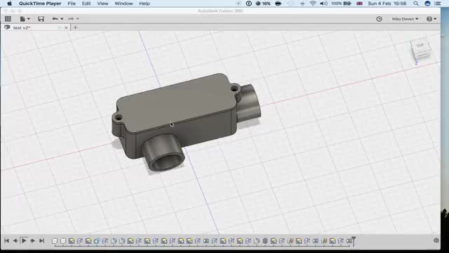
Fusion360
Autodesk’s Fusion 360 is one of the more powerful cloud-based parametric CAD programs out there, boasting nearly all the functionality we mentioned above. It can render parametric, solid geometry, allows for constrained and hierarchical design, includes simulation and testing, and even incorporates it’s own Computer Aided Manufacturing (CAM) tools in one package. Fusion 360 is sort of the new kid on the block, and rapidly catching up with big brother SolidWorks. Both hold a big chunk of the CAD market share.
SOLIDWORKS
SolidWorks is the big daddy of commercial CAD tools and is great at complexity and constraints. It can handle enormously complex designs and relationships where other tools may fail. It also has a powerful simulation engines to model forces, airflow, electricity etc. SolidWorks is now bringing it’s own cloud-based version called Xdesign which has the powerful Catia engine behind it, which what they use to build jumbo jets. As of writing this is still in a beta version.
Some pros and cons so far
According to various web reviews, Fusion has an edge over SolidWorks because 1. it’s free for students of life, the universe and absolutely everything and 2. it’s cloud-based, so can work cross-platform (Linux, MacOs, Windows). SolidWorks limited to Windows, so that rules it out for me. FreeCAD and Blender rock because they are genuinely free, open source and cross-platform but can be limiting in certain workflows.
Fusion360 also offers a great deal of flexibility, and a well-developed, versatile suite of tools all under one roof. The added bonus of in-program CAD to CAM workflow is a major plus, where in SolidWorks or Rhino you would have to fork out some hefty dollar for for pro-CAM options to optimise tool paths and configure G-code.
The downsides to Fusion360 is that you have to store your work in the cloud if you use their free version. Some hail this as a big advantage for file sharing but not great if you work out in the sticks and are continually offline. Or if you’re designing inter-continental ballistic missiles for Kim Jong Un.
Here is a little vid I made modelling in Fusion360. You can see here me trying various use of constraints, design hierarchy and parametric modelling.
Antimony
Antimony was developed by Matt Keeter and is in his words a CAD tool from a parallel universe. Here we see the power of procedural and algorithmic design, where each node represents a function that manipulate the data of that geometry.
The main power of Antimony is that it uses mathematical functional representations to create geometry where most other CAD tools will only represent 3D objects as a surface or boundary. Say whaaaat?
Check out Matt showing off Antimony. It’s pretty cool because you can see here the power of setting parametric relations as algorithmic functions.
B-reps and F-reps
In CAD tools, Boundary Representation (B-rep) represents the surface of an object, while Functional Representation (F-rep) in more advanced programs like Antimony will represent the surface as well as the volume inside a 3D object.
Rhino + Grasshopper
Rhinoceros is a primarily Nurbs-based 3D surface modelling software. As you can see in the image above, think of a Nurbs surface as a mathematically defined digital membrane. It is an infinitely flexible, thin (you need to create solids out of them) and can be manipulated in various ways by using control-points. It is rendered using a boundary representation.
Rhino is very good for free-form 3D modelling, and as we can see at Fab Lab Barcelona, the architects love it. It’s a relatively light-weight and can easily create curves, surfaces, open and closed polysurfaces (even meshes) to model any shape you can imagine. Since it is Nurbs-based it is easy to convert an object into a mesh .stl file for 3D printing or other CAM work flows. It has both a Windows and Rhino for Mac version.
Grasshopper is a visual programming language for Rhino that allows for both parametric modelling and algorithmic design, sort of like we saw with Antimony (except without the f-reps). It adds infinite options to Rhino modelling by expressing the design as a definition and adding interactive elements to the geometry. Grasshopper previews the geometry in Rhino without generating it, so allows you to make instant changes to specific parameters in an instant and lightweight way.
In Grasshopper, you don’t work on the real geometries. Rather, you work on the logic behind the geometries.”
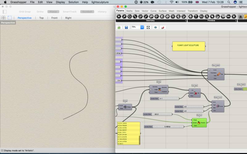
Computational design in Grasshopper
First there was a curve:
Rotating the curve by 360 with a variable number of steps:
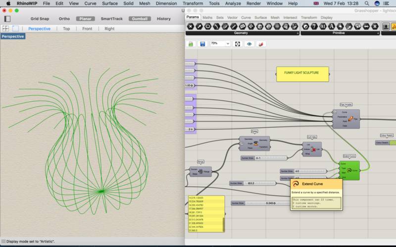
Cull the index by -1 and extend the curve with a number slider:
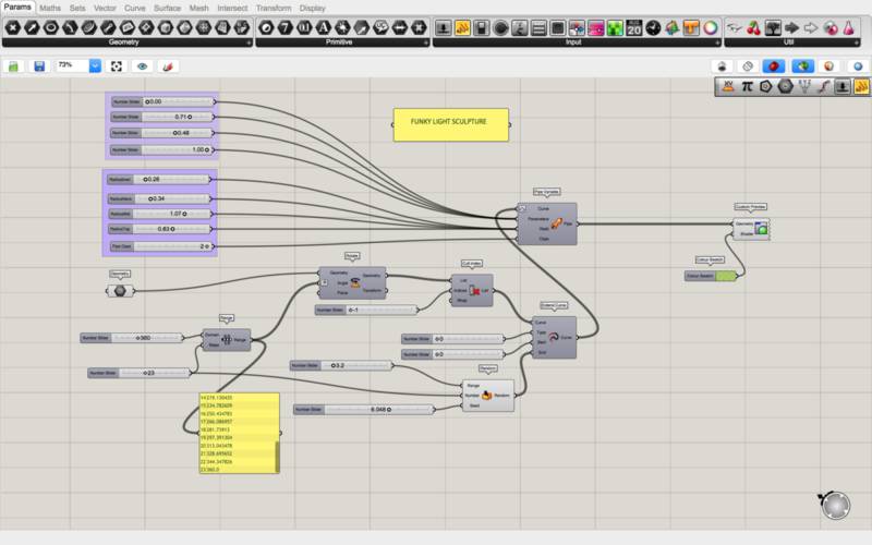
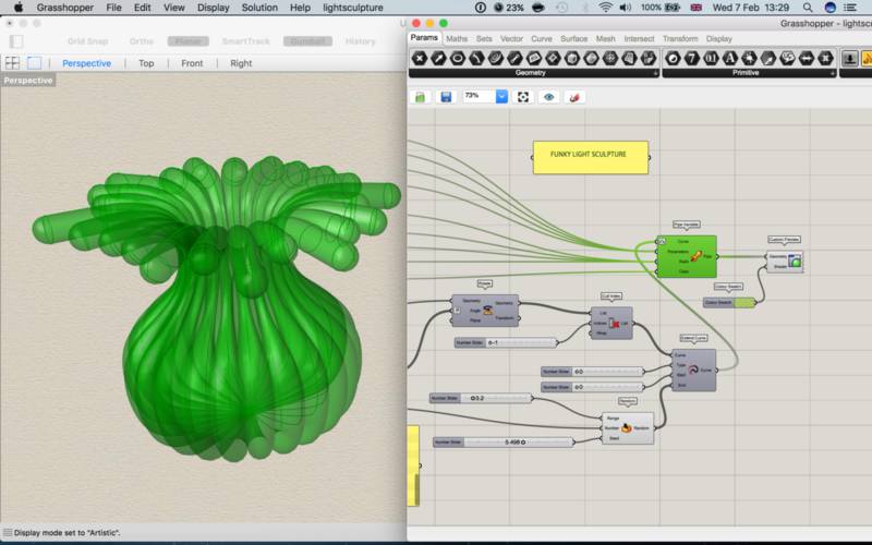
Attach the random generator to vary those extensions, then add the pipe component to create a solid geometry out of the curves:
Modelling a Final Project
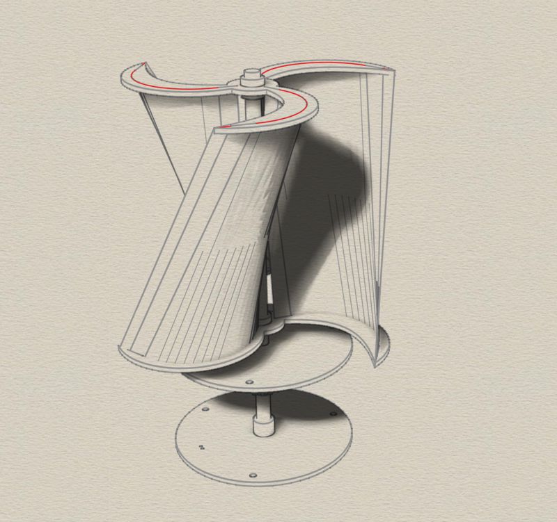
For my Final Project I am going to prototype a vertical axis wind turbine. This is quite a technical challenge for me, but I really think that it is possible to make a small prototype and learn some valuable skills in the process.
For this I have decided to stick to Rhino and Grasshopper to be able to better learn computational design and parametric modelling. This is a bit of a challenge for me, but I have been teaching myself programming and I find the more i dig into Grasshopper it allows a lot of flexibility in controlling geometry. I will also be suing Fusion360 extensively for the more technical parts of the modelling process.
Here are some first models:
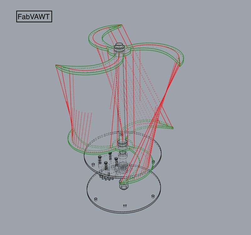 |
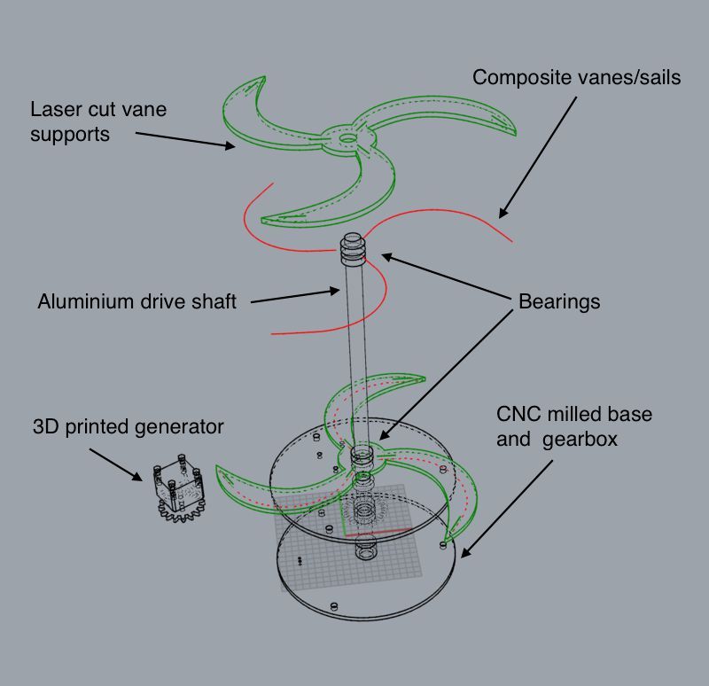 |
You can download all my design files for wk 3 here from the Gitlab repository.