Wk5. Electronics Production
-
Group assignment: Characterise the specifications of your PCB production process
-
Individual assignment: Make an in-circuit programmer by milling the PCB, then optionally trying other processes.
Group Assignment
For our group assignment I joined forces with Eve, Carolina, and Aitor to learn the specs of the PCB milling process, mill the line-test file using the 1/64 tool bit and test the parameters of our tool.
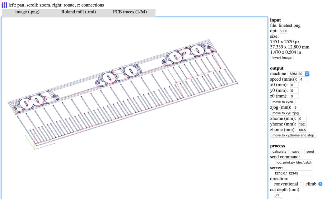
Fab Modules
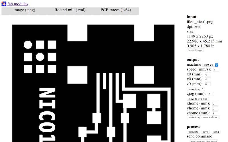
Using FabModules we set the input format to image (.png) and uploaded my file. The traces file should now be visible. Then set the output format to Roland mill (.rml) as these are the machines we use. Finally in process set to PCB traces (1/64) for the traces file and the repeat the process for PCB outline (1/32) for the outline (see below).
These are the traces we will mill with the 1/64 tool:
 And this is the outline we will cut with the 1/32 tool:

Output Settings
We then modified the settings on our input on the right, much as is showed in this video selecting the output machine to our SRM-20 Roland Mill.
For our machines we made sure the x (mm) y (mm) z (mm) and xhome (mm) yhome (mm) are all set to 0.
The only exception is zhome (mm) which we add a 5 value. This is specific to our machines, and makes sure the spindle will raise the tool before returning to the origin when finished milling. Without this zhome margin, the tool risks scratching its way back across the surface of the board ruining both bit and board.
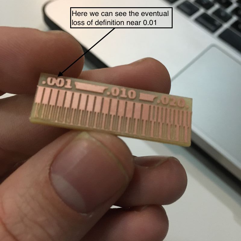
Below you can notice the 4 offsets the simulated tool path makes, and how with a 1/64 bit it will not completely define the traces which are closer together.
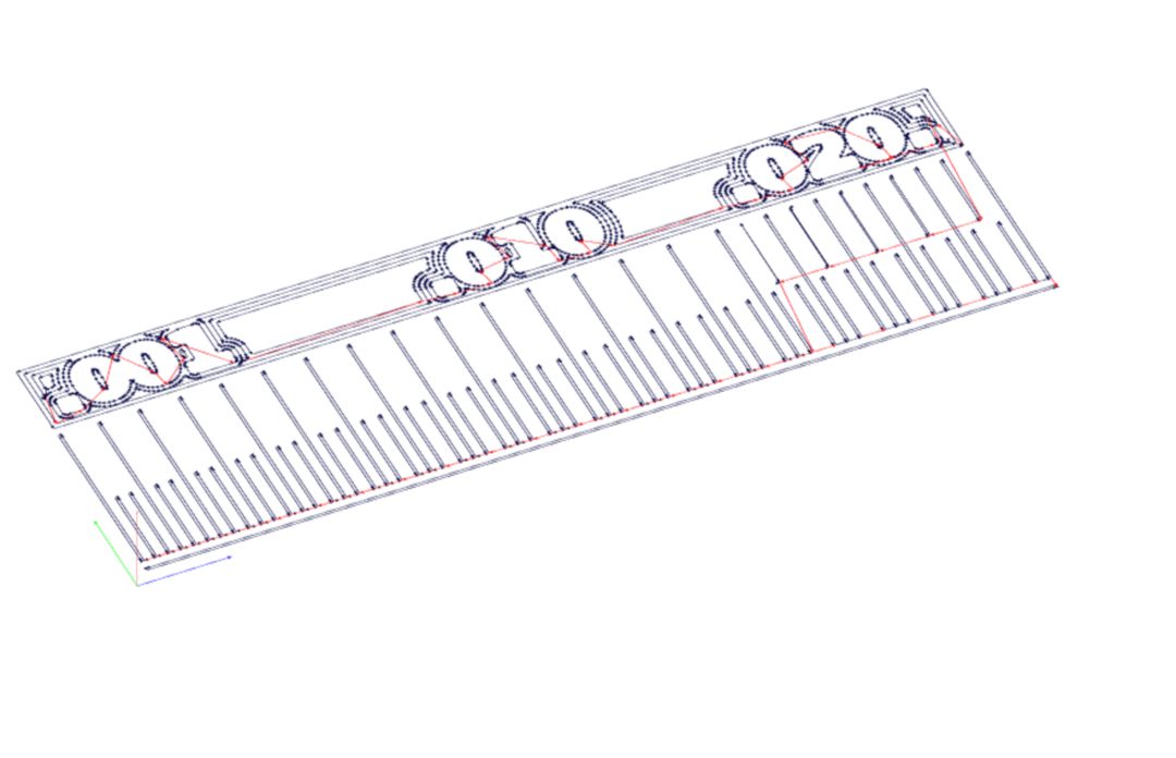
Process and Offset
Under Process: Calculate, Fabmodules will show you the exact path the mill will trace on your board. Here you can modify the cut depth, tool diameter and other settings which modify the path the spindle will trace. Of interest to us is the number of offsets (4 to fill is a good minimum): which makes sure the mill traces 4 lines to offset the circuit path. This is amble to make sure it doesn’t short with the remaining copper on the board. Alternatively, you can set it to -1 which will tell the mill to continue offsetting to remove all the copper on the board which is not part of the trace or outline. This will take longer. You can see how this works again by pressing Calculate.
Save
Finally if happy, press save and FabModules will save a .rml file which if opened in a text editor looks like complete gibberish, but if you are a Roland machine, this should sing like poetry.
Outline
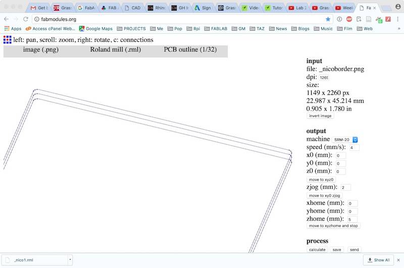
Repeat the same process with the PCB Outline .PNG file, selecting it in the input only making sure the Process is set to PCB Outline (1/32). The output and process settings should be the same, and we do not need to worry about offsetting the outline.
When you press calculate you should see a 3-tier wire diagram which shows how the mill will run round the traces I already cut 3 times to cut through the board.
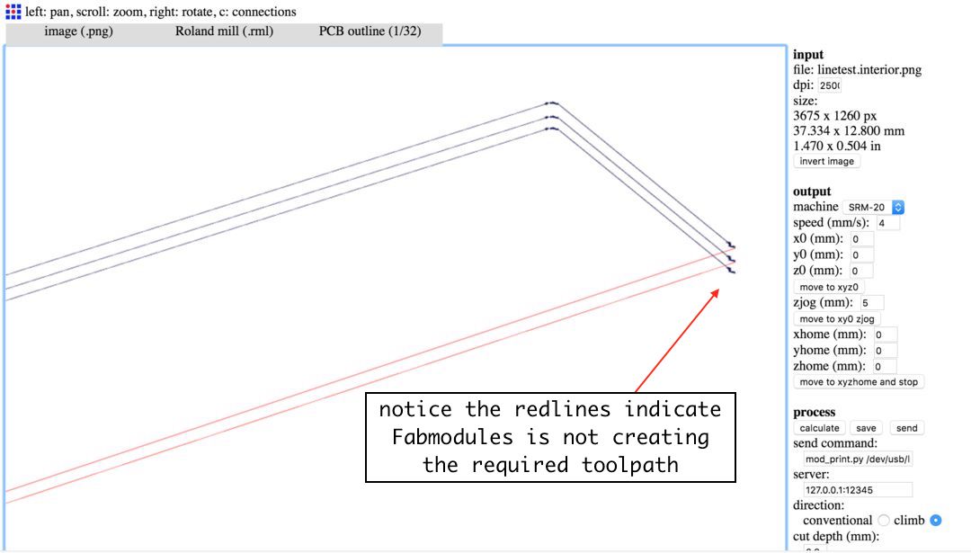
Issues with the toolpath
Here as you can see FabModules did not create the required tool path for the whole outline. We only realised this during the milling as basically it only “cut” three sides of the outline and skipped the bottom side!
We figured this was a problem with the PNG image, and rather than opening it in an editing program, we found a quick fix which was to flip the png and simply recreate the .rml file. Considering there were other groups waiting to use the RolandMill this worked perfectly.
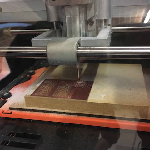
Milling the PCB
Working the MonoFab
Milling the PCB was tricky in terms of getting the hang of the work flow of the Roland monoFab SRM-20, but once mastered that, the process is straight forward. Here described:
-
Make sure the floor of the mill where the board will sit is clean of any gunk or sticky stuff. A bumpy surface can ruin your board or break the mill bit.
-
Make sure the PCB board is flat, use a ruler to check the surface.
-
Use double-sided tape to stick the board onto the mill floor, keeping it more or less aligned to the edges.
-
Add the mill bit: 1/64 for traces and 1/32 for outline. Once done with the traces, change it for the outline bit 1/32 which is thicker and can cut through. Watch out for not tightening the bit too much and that the bit does not wiggle as it is easily breakable.
-
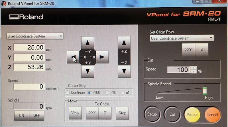
Find the X/Y axis using the
Cursor Stepto control movement in increments of x100, x10 and x1 to find the origin. This should be more or less on the corner of the board, or next about 5mm from the last cut if one is sharing a board. -
Set the Z axis under:
Set Origin Pointby bringing the bit down incrementally so it nearly touches the board, then un-tighten it and manually lower it gently until it touches the board. - Set the X/Y axis under:
Set Origin Point. - Press
Cut, load file, thenOutput. The spindle will start immediately. - Adjust the speed down to 40% to begin with to make sure the spindle is working in the right direction, if all is good bring it up to 100%
- DO NOT TOUCH THE SPINDLE SPEED! This should be left at 100% at all times.
- You can
PauseorCancelthe milling at any time through the Roland interface. To stop immediately lift the plexiglass shield and the operation will immediately halt. PressVIEWto inspect the PCB. Watch out not to reset your coordinates by mistake in the middle of the milling.
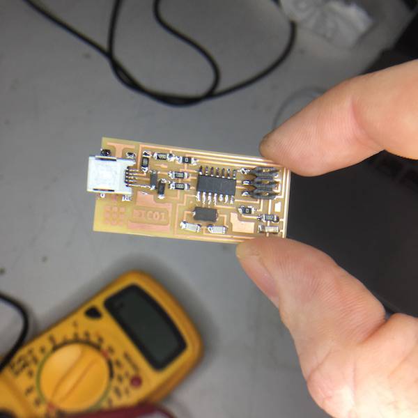
Individual Assignment
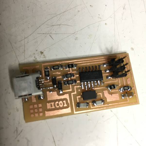
Here that task was to make an in-circuit programmer by milling the PCB. As this is all new territory for me, I decided to work with Neil’s FabISP design and keep things simple. But since the outline and traces are .PNG files, I couldn’t help putting my mark on my very first programmer using photoshop, then re-exported the .png file. I only needed to do this with the traces file as the outline stays the same.
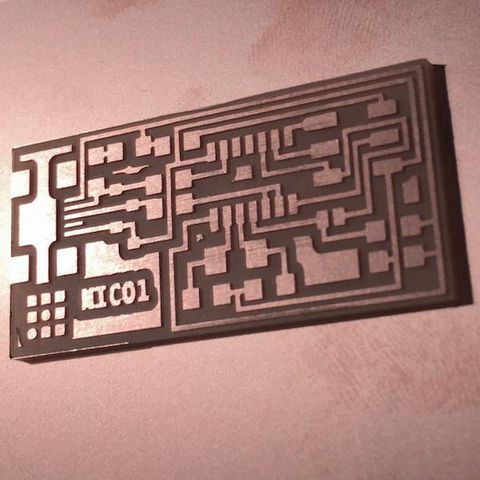
Here as you can see the outline toolpath came out fine:
I milled two boards. The first came out wonderfully, see pix below:
 |
 |
Failures:
On the second board I tried to mill I managed to break not only the 1/64 bit but also the 1/32 bit! This was a little embarrassing, but I’ll document it here all the same and next time hopefully, fail better :)
Re-setting the Z
At first one of the problems was that although I had set my X/Y axis and then by Z axis perfectly, the Roland began to mill the traces a good 10 cm above the actual board.
I reset the X/Y and Z axis, and same problem. I went back to the FabModules and redesigned my traces, then started again, and same problem!
It turns out what happened was that the Z axis was set all the way down to the limit of the Roland mill’s vertical axis extension; not allowing it to actually mill the board. So when this happens, the machine automatically raises its Z axis to the top and goes through the motions in thin air.
Solution: When setting the Z its imperative to make sure the bit is brought down gently to touch the board, using a part of its length to make up for the Z axis. This way the machine has leeway to operate on the Z axis. Another solution may be to raise the board higher on the surface, but I did not attempt this for time.
When I fixed this, the machine seemed to mill as required, only when I checked out the result in View it had not quite finished all the traces, and it turned out the 1/64 bit broke in the middle of the job! This may have been due to my carelessness in bringing down the bit manually, letting it drop rather than letting it touch down gently. These tools are quite brittle.
Speed Spindle
I decided to continue all the same with my outline, as I already had a board and wanted to get on with soldering. I did the set up fine and when I got it going, only for the 1/32 bit to break in mid flow! AAAAARG.
What went wrong for me here, is that when I adjusted the speed down to 40% I must have also adjusted the speed spindle speed below it by mistake. If the 1/32 spindle is digging its grooves, slowing down its rotation only means it meets with more resistance eventually breaking.
LESSON: DO NOT TOUCH THE SPINDLE SPEED WHILE IT’S WORKING!
Stuffing/Soldering
The soldering went quite well for me. I have done a fair bit before, never on such tiny parts, but I had a general grasp of the method. Never the less, I’ll outline Neil’s method for good practice below. But first finding the parts:
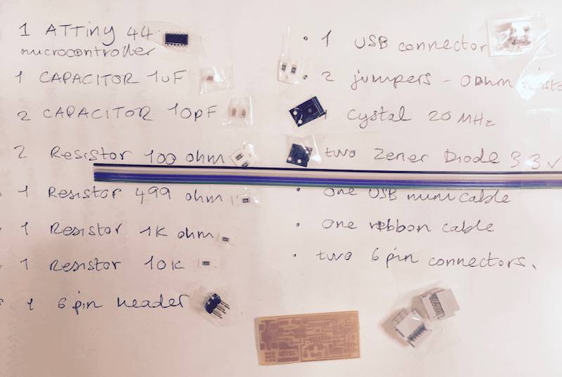
Finding the components:
One of the trickiest parts of stuffing the board was actually finding all the tiny components and making sure they were well named, and then figuring out where they would actually go and in what direction. The fab academy electronics production page helped.
I organised my components in my notebook using tape, a fairly caveman method which nearly had me confusing two of the resistors. Next time print out a list and have this more organised.
IMPORTANT! ALWAYS PUT ELECTRONIC PARTS BACK INTO THEIR PROPER DRAWERS AFTER REMOVING.
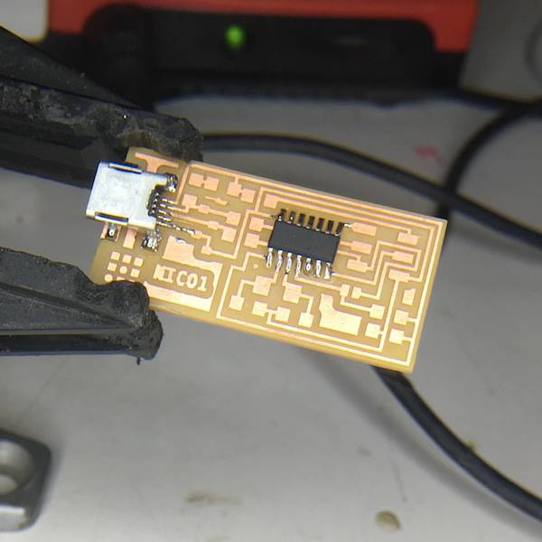
Stuffing the tiny parts
Soldering board it was good to start from the inside out. The trickiest bits were of course the Tiny 44 micro-controller and the mini USB header.
I found with these tiny parts its easier to solder down opposite corners first, putting a tiny bit of solder on the board first, then using the tweezers to hold the bit in place (magnifying glass helps).
Then just place the iron on the connector without adding more solder so that the heat is transferred and the piece sticks.
Once the bit is in held place by opposite joints, it’s easy to go around and do each individual connection without fear of jolting or moving the components out of place.
IMPORTANT! MAKE SURE TO FIGURE OUT WHICH PARTS HAVE POLARITY AND NEED TO BE SOLDERED IN A CORRECT DIRECTION!
Soldering wisdom:
- Heat soldering iron and clean to get gunk off tip. If tip is dirty the heat will not transfer effectively.
- Tin the tip by getting a layer of molten solder on the tip so that it is shiny.
- Put the tip at the boundary of the joint.
- Feed in more solder to make a blob.
- Wait a second as the blob transfers heat into the joint.
- When the blob starts spreading, feed in a little more solder. If this is done too early the blob will only accumulate on the iron and not transfer to the joint. Then clean iron and start again.
- Wait with the solder on the joint, heating a little longeras the solder “wets” the joint and spreads.
- Remove the iron.
- A good soldered joint should be nice and shiny, with not too much solder and not too little. Make sure that it is not touching any other connections and that the component sits flush in place with the board.
 |
 |
Smoke Test and Programming
Checking connections:
First things first, was giving the board a good visual inspection, checking that all the soldered joints were nice and shiny, and that there was no overlap. I then used the the multimeter to check that the power and ground are not connected and that there was no shorts on the power line.
So far so good. I then plugged my FabISP into my computer via the mini USB cable. I did not get an error message and the board did not start to smoke so it seems all good. Proceed to programming.
Programming:
This part also went quite smooth for me, apparently because I have a swanky Mac and this is just easier to do in MacOS or Linux than on Windows. Basically, I just followed the instructions as per the Fabacademy programming page.
Downloaded and installed the Crosspack AVR.
I first downloaded the FabISP firmware, unzipped and left the folder on the Desktop. I then powered up the board with our ATAVRISP2 Programmer. Lucky for me I got a green light which means my board is receiving power.
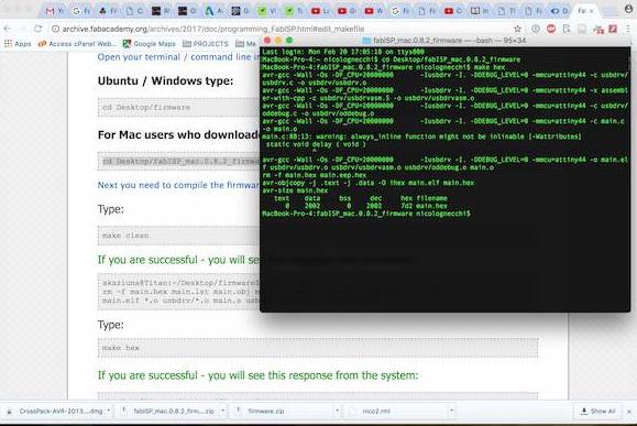
I already had XCode to compile C-code so I could proceed directly to my Terminal window, and edit the Make file with the following commands:
cd Desktop/fabISP_mac.0.8.2_firmware
Then:
make clean
I got the following:
$ make clean rm -f main.hex main.lst main.obj main.cof
main.list main.map main.eep.hex main.elf *.o usbdrv/*.o
main.s usbdrv/oddebug.s usbdrv/usbdrv.s
Then:
make hex
Then:
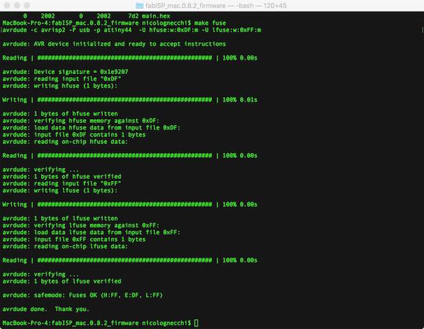
make fuse
Then:
make program
 |
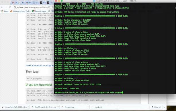 |
YAY! Success!!
Once this was done, I unplugged the board and programmer, and to verify that my ISP is working correctly I went into my Apple menu: About this Mac: System Report. Under Hardware: USB, the FabISP appeared. Phew!
Removing the 0 ohm resistors
Lastly, I went back to the soldering table to remove my 2 tiny 0 ohm resistors so that I can use it as a programmer to program other boards.
My very own FabISP programmer!