Wk8. Computer Controlled Machining
This week we make something BIG
- Group assignment: test runout, alignment, speeds, feeds, and tool-paths for your machine
- Individual assignment: make something big!
Guerilla Milling
If you are new to CNC milling, as I was, I definitely recommend perusing this guerrilla guide to get an understanding of how three-axis machining works. Also speak to your workshop supervisor to understand the machine you will be using. At the Barcelona Fablab we have a wicked wiki for the Shopbot and great links for all that comes with CNC milling. At the moment of writing we also have a Presix machine, but it is currently out or order.
Bits, Feeds, Speeds
The challenge of getting a good CNC cut is in selecting the best tool for the job (Bit), the optimal cutting speed (feed rate) and router/spindle RPM (speed of rotation) for your material.
Flutes
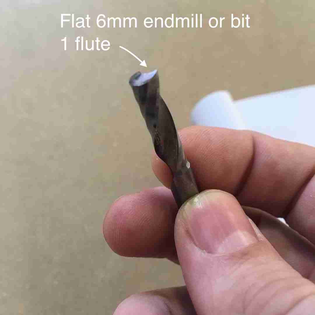
The end tool or Bit closely resembles a drill: it consists of a round shaft with several blades (flutes) wrapped around it in a spiral fashion. The difference is these flutes have a sharp, exposed edge running along their entire length. This is because the bulk of their work is meant to be done by moving sideways, like so:

The right bit for the Job
-
Milling bits (also called milling cutter or end mill): are made from a variety of materials. The most common are solid carbide, carbide-tipped steel, and high-speed steel.
-
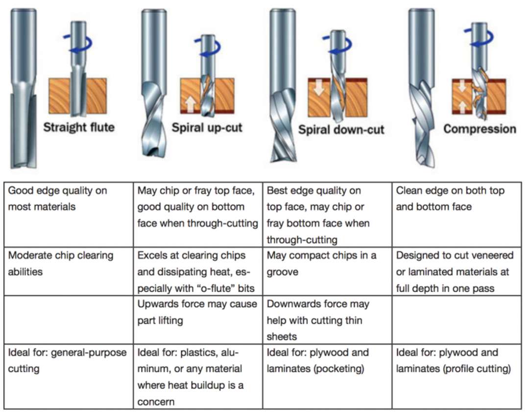
Flute type: There are four basic flute types: Straight, spiral up-cut, spiral down-cut, and compression. Each type has its own advantages and disadvantages, which are outlined in the chart below.
 |
 |
Changing Endmill
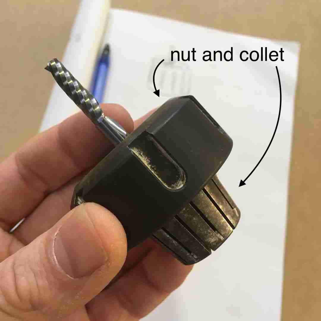
To remove the bit place the nut firmly in the Shopbot toolchangeing holder and lock with white lever. Use the spanner to unscrew the nut anti-clockwise like so:
 |
 |
-
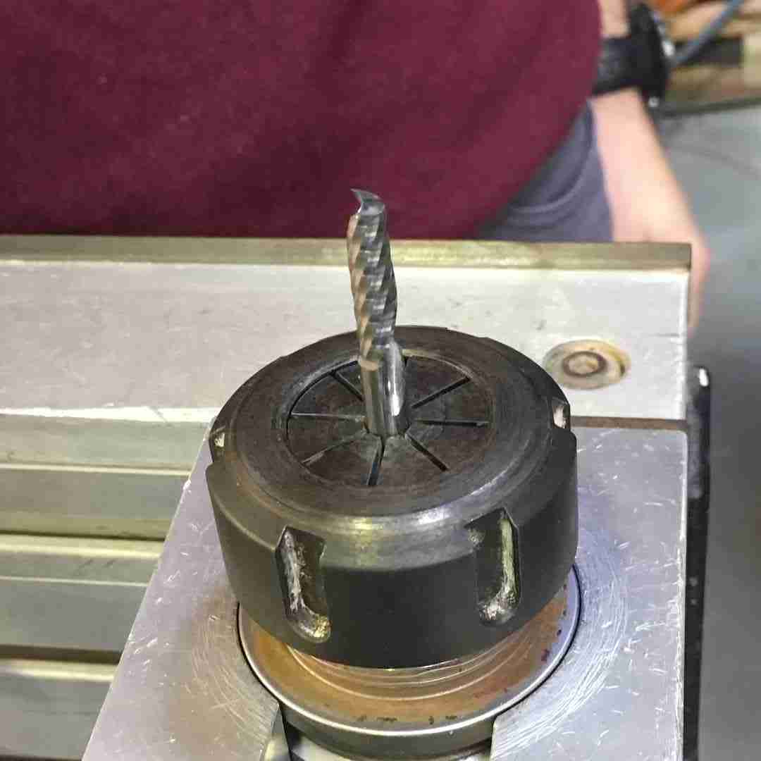
Remove the collet using your thumb as a lever, and remove the endmill.
-
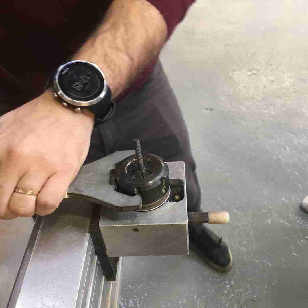
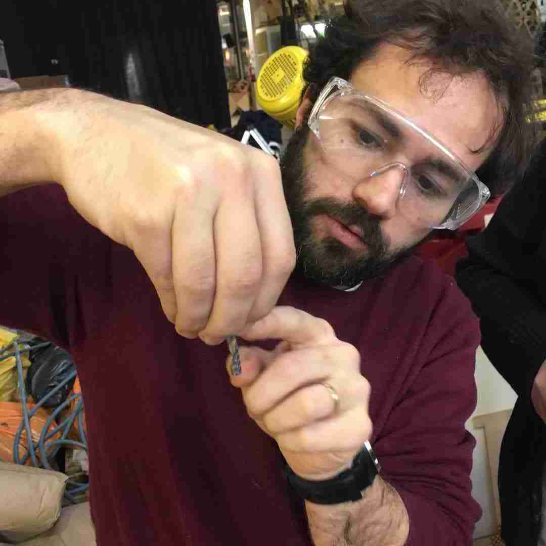
When adding a new bit make sure to leave a 2-4mm margin between the end of the flute like Santi is showing.
Chipload
Chip load is the size of the chips produced during cutting. This is dependent on the Bit you are using and the cutting speed. The goal is to get the maximum chip load possible to increase productivity, reduce heat, and prevent the tool dulling.
When the chip are too small (or you are producing sawdust) the Bit can overheat and dull quicker. When chip load is too high, the tool can deflect creating a bad surface finish and, in extreme cases, even break the Bit. I used the Fablab Speed and Feeds Calculator to determine the chip load for plywood.
Test Cut Group Assignment:
For the group assignment we made a test cut on the FabLab ShopBot to test the machine, various speeds and feed settings, as well as an overview of RhinoCAM to create tool-paths for the CNC.
CAM Strategies and G-code
CAM stands for Computer-aided Manufacturing. It is basically a software that creates a set of strategies from your geometry that it will then convert into G-code for the CNC to follow. G-code is a sequence of painfully basic instructions that actually make sense to the controller embedded in the mill; say, “set speed to 12,000 RPM” or “move cutter to X = 10.245, Y = 5.000, Z = -2.000”.
RhinoCAM
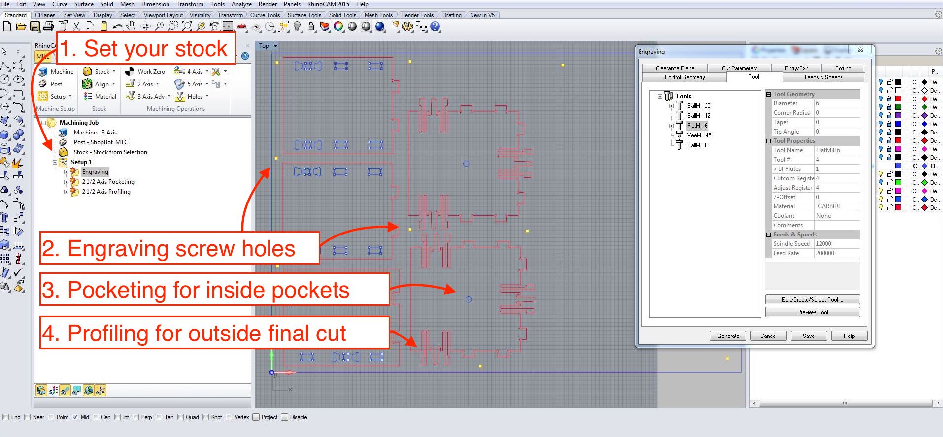
So before cutting we need to create our toolpath using RhinoCAM is an proprietry extension plugin for Rhino, however it also comes with FreeMill which is free and covers most of the 2d milling processing we will be doing in the lab. RhinoCam is not intutive but there are also some good tutorials worth watching to get a hang of how it works. Fusion360 also has it’s own in-program CAM processor which would be worth exploring. But here is a break down:
-
Carefully measure the stock you will be milling and draw it as a closed curve into the top viewport in Rhino.
Extrudethis curve in -Z to the exact thickness of your stock. Basically, the top surface should be aligned with your X/Y C plane. -
Place or nest your geometry within the stock, remember this should be in 2D for the machine.
Make2Din Rhino is your friend. Separate your cuts into different layers for your strategies. Here you want to think, what will be pocketed and what will be profiled, what will be cut from the inside and what will be cut from the outside. -
Use the
Pointsin Rhino to strategically place where you want your screws to go. Don’t place them to tight to your cutting curves, make sure to account for a 10mm diameter for the screw head and 6 mm (of whatever tool) diameter you will be using.
Choosing your strategy
- In Rhino, type the command RhinoCAM to open.
- Make sure you are in “Mill” strategy, a mode that is for Milling
- For this assignment we will selecting options under “2Axis” as 3D axis is more for milling surfaces. Under this we have:
- Pocketing: this is for creating pockets which will hollow out.
- High speed pocketing: does a spiral pockets
- Profiling: follows a line from the inside or outside.
- Engraving: follows the vector from the middle.
- V-Carving/V-Carve roughing: creating
- Chamfering:
Whenever you choose a strategy in RhinoCAM you enter this funny window which has strange tabs that seem move about all the time, which can seem disorienting. But basically here is what you have:
- Control geometry: like this is where you select your geometry in Rhino
- TOOLS: like above, this is where you select your end mill, and set feeds and speeds.
- Feeds & Speeds: Here you can change or adjust the feeds and speeds for a particular strategy.
- Clearance plane: See below, is how high a margin the tool will “clear” while moving between cuts.
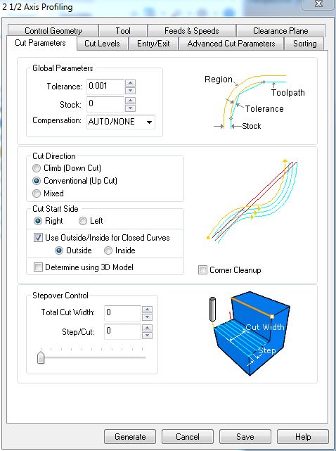
- Cut parameters: Here is where you set your
Tolerance,Cut-Direction>ConventionalorClimbdownand whether it is anInsideorOutsidecut. For pocketing it gives you whatCut Patternyou want to follow, ie. spiral, linear etc. - Cut levels
- Entry/Exit
- Advanced Cut Parameters
- Sorting
Selecting the Tool
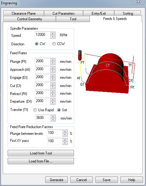
This will bring up a window like this where you can manually enter your feeds and speeds, or under the tab Tool you can selece the tool you ar going to be using, in our case Flatend 6mm and under Feeds & Speeds you can set the speeds you want for this tool. Tehn select Save Edits to Tool and when you are back in your strategy menu, under Feeds & Speeds you can Load from Tool.
 |
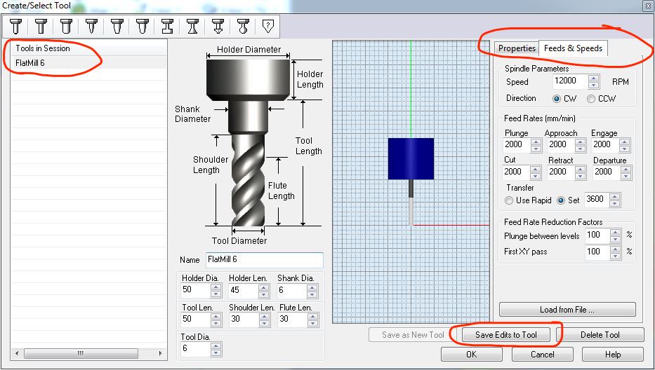 |
Above you can see that your feeds and speeds for the 6mm endmill on Plywood were:
- Speeds: 12000 RPM
- Plunge: 2000
- Approach: 2000
- Engage: 2000
- Cut: 2000
- Retract: 2000
- Departure: 2000
Engraving
-
We use engraving here to both mark screws and make quick dogbones. Basically we use it to drill holes that will mark the stock, so that we will can then use a hand drill with a smaller diameter tool to make pilot holes for our screws. This way they can grip onto the material.
-
Under 2 Axis > Engraving when it says
Select Drive Containment Regionsselect all your screw points toy made before. Alternatively, click on their layer andSelect Objects.
Pocketing
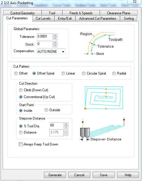
Here note the Cut Pattern is set to Offset Spiral This will mill my pockets in a spiral fashion. Conventional UpCut is standard for plywood, this means the Bit will be cutting upwards. Bear this in mind, your cleaner surface will be on the bottom.
 |
 |
Profiling
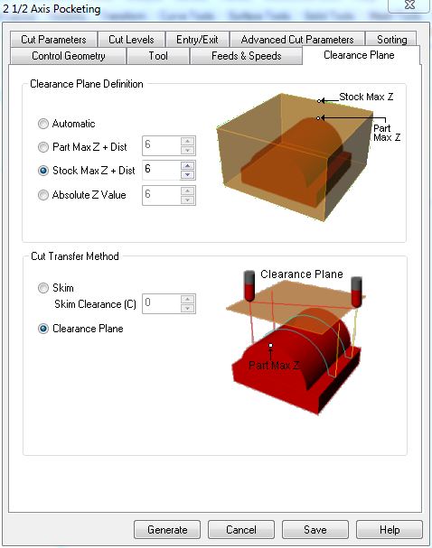
Note the choice of Outside to tell the machine to follow the outside of my curves. On the left we can see the clearance plane is set default for Stock Max Z + Dist 6 and I kept this for profiling as well.
 |
 |
Simulate and Post
Once we have all our strategies, it’s good to simulate them to check everything is cutting the way and direction we want. Then one by one, click on the strategy and POST. This will generate G-code in text-edit file that is basically a lot of commands and coordinates that should be poetry for a CNC.
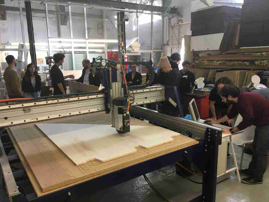
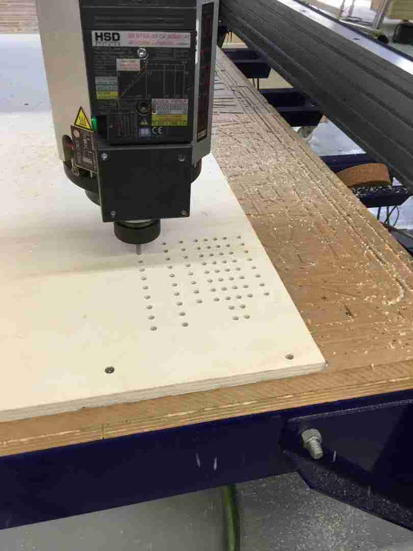
The ShopBot
ShopBots are good friends of the FabLab network and FabLab Barcelona has a full size PRSalpha ShopBot CNC with a working area of 4270 x 2310 x 1730 mm. You can read more about the performance specs.
Preparing the ShopBot for Action
-
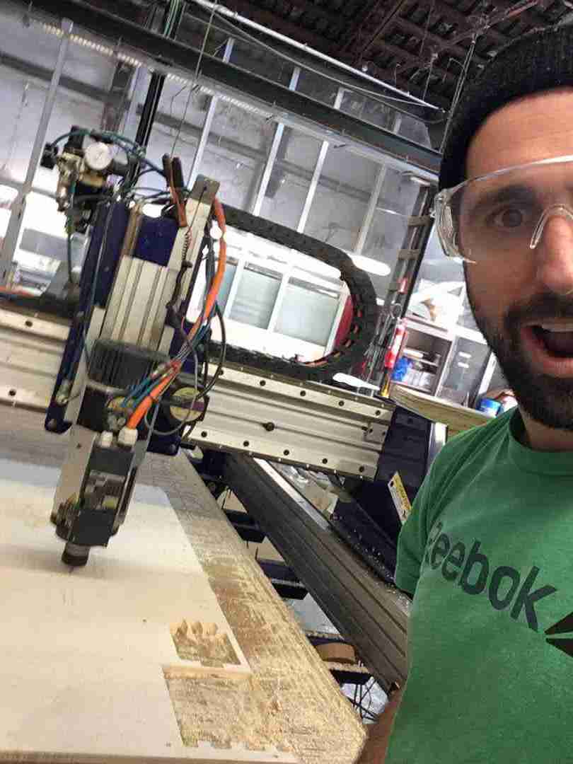
First and foremost, SAFETY. Make sure hair is tied back, loose ends are tucked away and we all have eye protection. Things do go flying.
-
Make sure the bed of the machine is clean before use. Inform us if it is not clean.
-
Securely fasten your material to the bed of the machine.
-
Type command “C3” in the ShopBot interface. This is a “Homing” routine to establish the true machine home X-0 Y-0 (in the machine coordinates system)
-
Jog X, Y to your personal Work Home coordinates, ie: the corner of your material & the X,Y origin of your drawing.
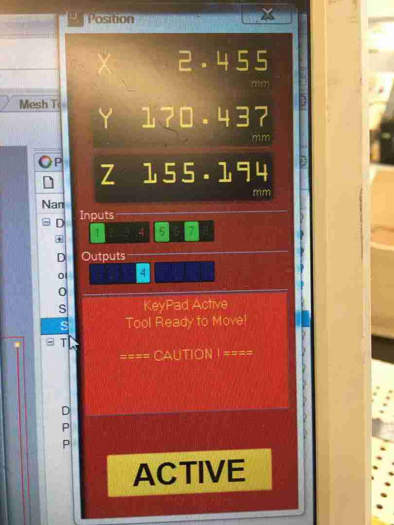
-
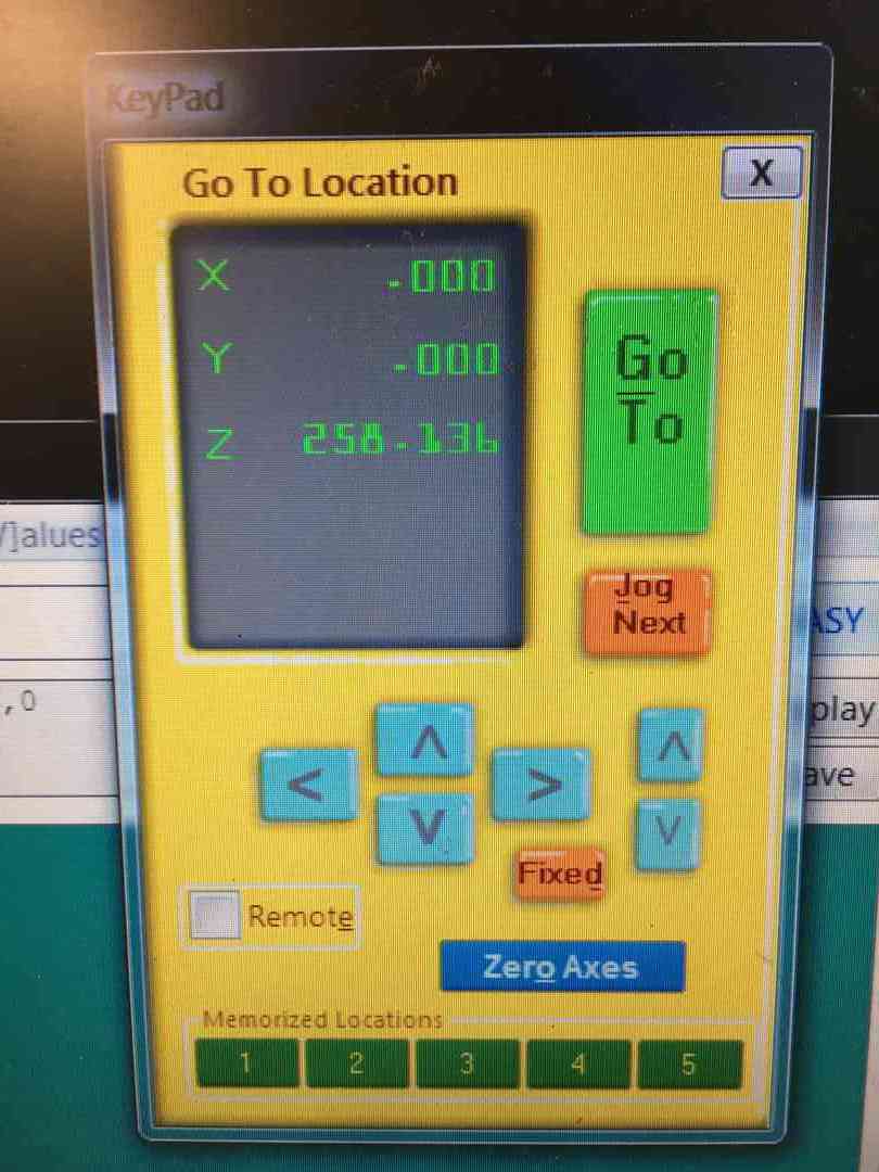
Take a photo of the Control screen keypad to remember the coordinates of your chosen Work Home position in case of power outage or emergency stop. Example: X - 105.499, Y - 145.376 (do not worry about Z yet). Work Home X Y coordinates are simply offset measurements from the true Home (X-0, Y-0) of the Machine.
-
Zero work coordinates to X-0 Y-0
 |
 |
-
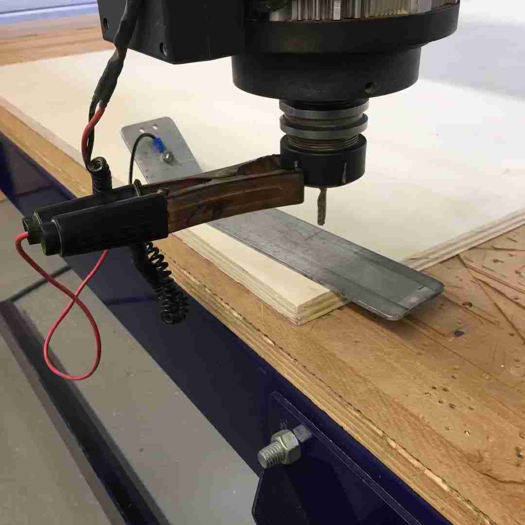
Place the Z-0 plate directly under the tool on your material & place the Alligator Clip onto the collet nut on the tool holder. Use command ”C2” to set the Z-0 of your home position coordinates. You now have all 3 of your X, Y & Z work home coordinates loaded into the CNC system.
-
Load G-code file which you have previously saved in te shared folder.
-
Visually check again the machine bed to ensure all tools have been removed and that material is securely fastened to the bed.
-
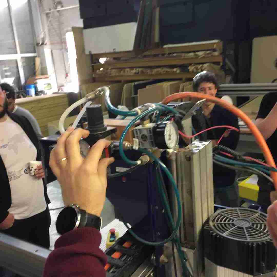
Turn on the spindle air cooler from the valve. You should both hear it and feel the air below the tool.
 |
 |
-
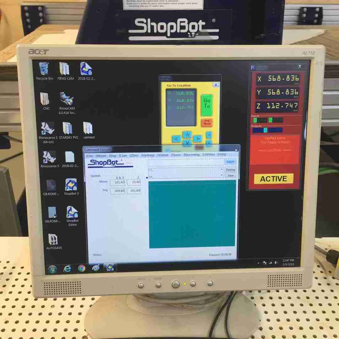
Start in ShopBot software, follow prompts.
-
Start the spindle with the green button on the ShopBot remote.
-
Monitor the machine closely until the machine stops. Never leave a working CNC unattended.
-
If you need to pause the machine, press the Spacebar on the PC Keyboard. The machine will pause, then follow the prompts to restart or end the process.
 |
 |
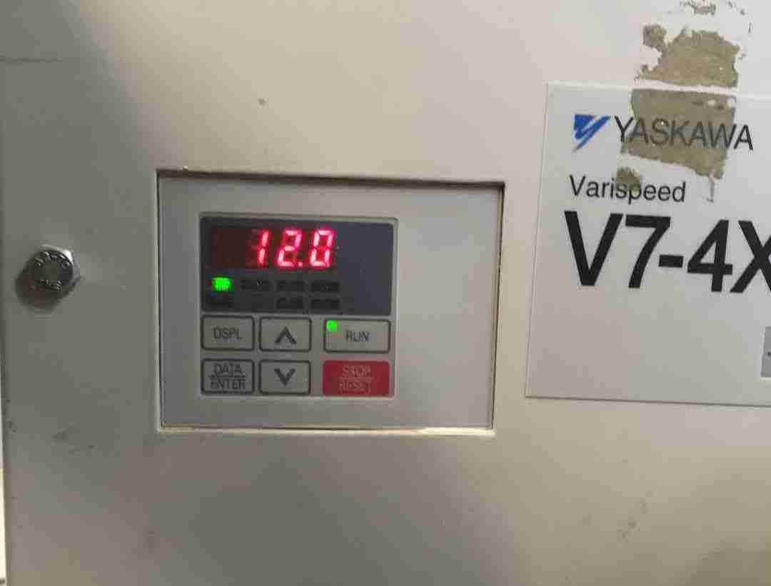
NOTE: Above left is actually the spindle speed that needs to be set manually beside the machine, as this particular ShopBot will not read RPM from the G-Code.
Group test conclusions
With Santi’s test cut we established that for our Plywood material, the idea parameters for the Flat 6mm, 1 flute endmill are:
- RPM: 12000
- Plunge: 1000
- Travelling clearance plane: 4000
- Rest of the parameters:2000
- Step down: 4mm max (always depending on the diameter of the tool)
Test cuts
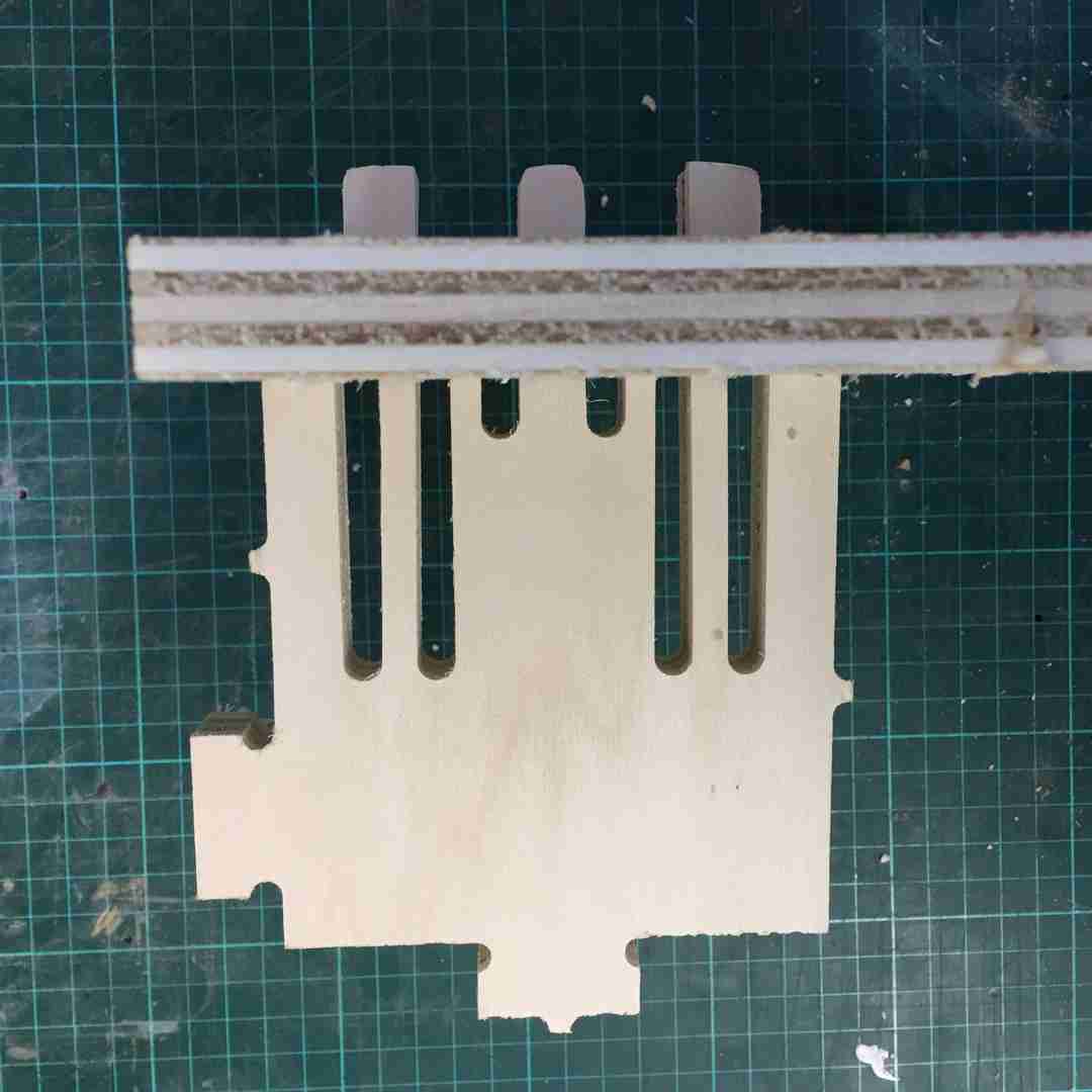
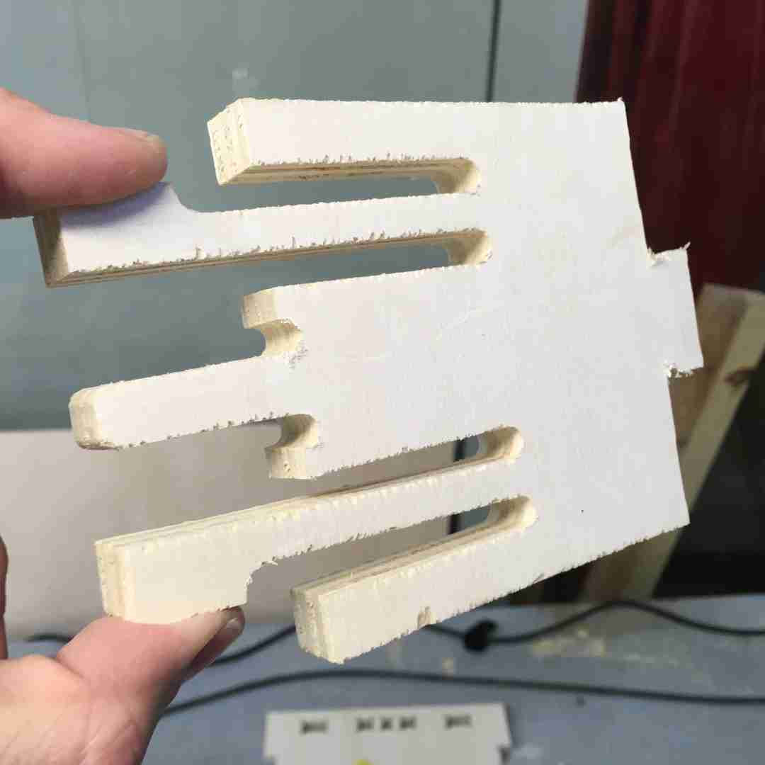
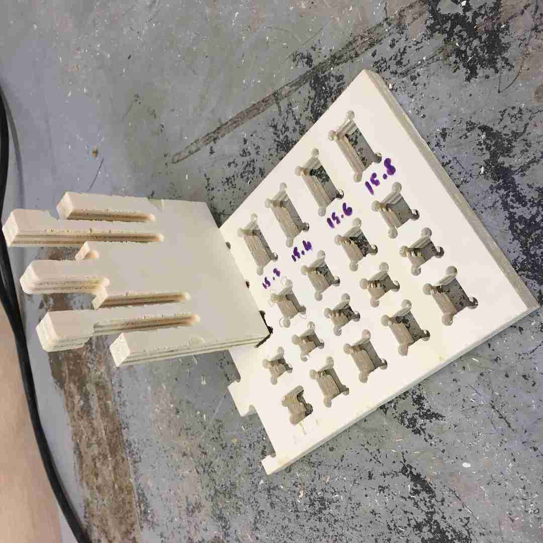
I took advantage of some space in Santi’s demo board to test cut my clip tenon design, and at the same time establish some press-fit tolerances for the group project.
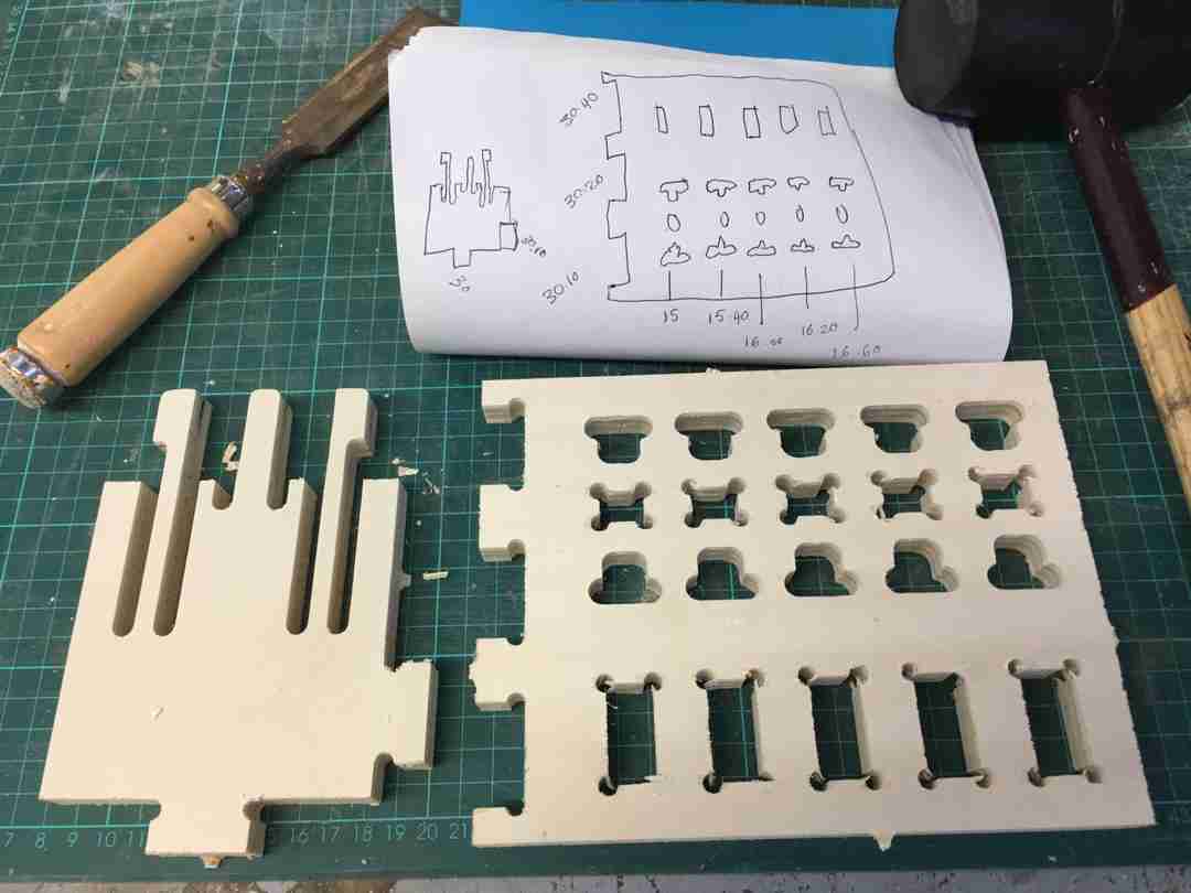
Basically, here I created varying tolerances with 0.20 mm increase for my clip holes as well as a slot joint and side press fit. Here we can see .40 offest being a comfortable fit for the clip tenon.
 |
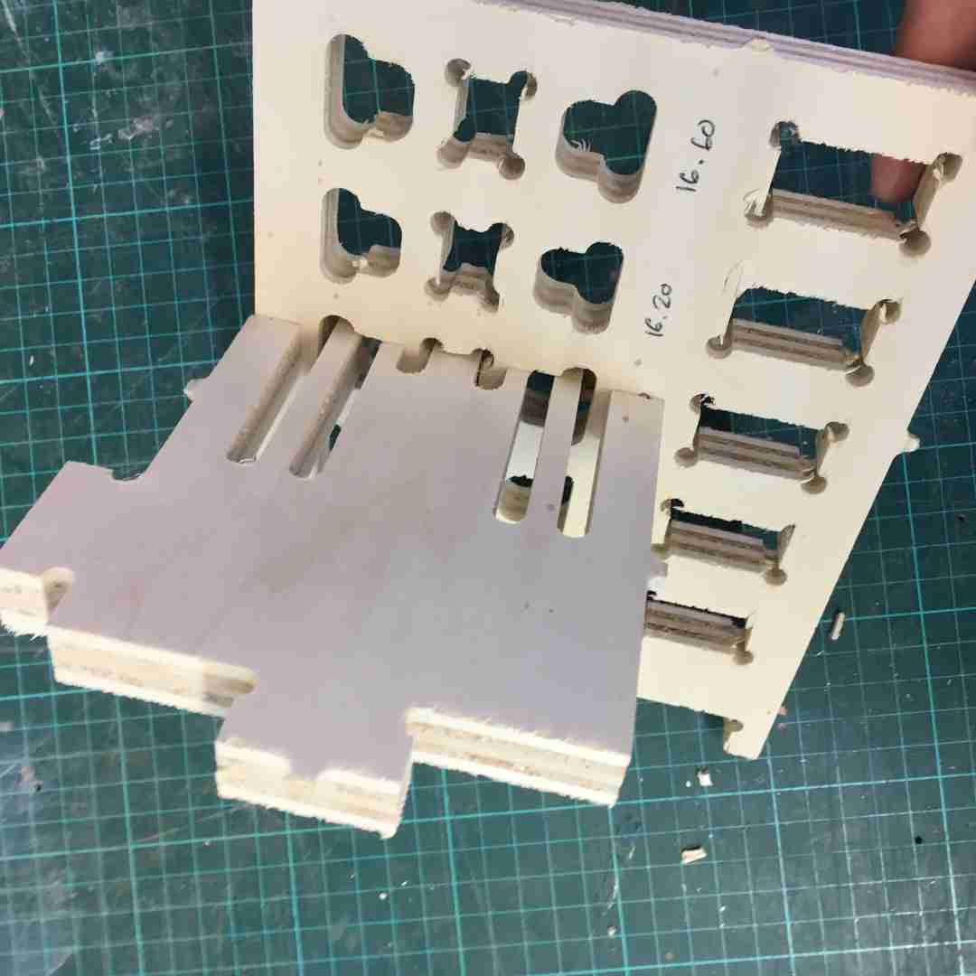 |
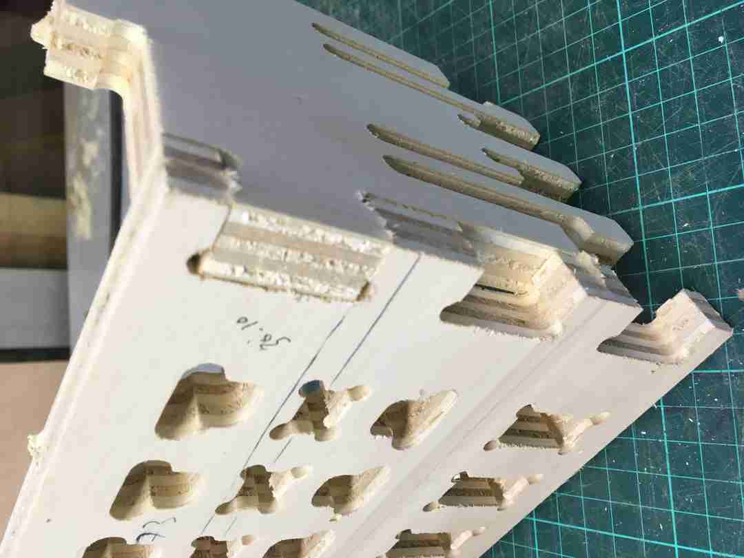
And amusingly, 0.10 on the side appeared a much more snug fit. I was expecting 0.40 but as you can see on the right, it had way too much wiggle room.
 |
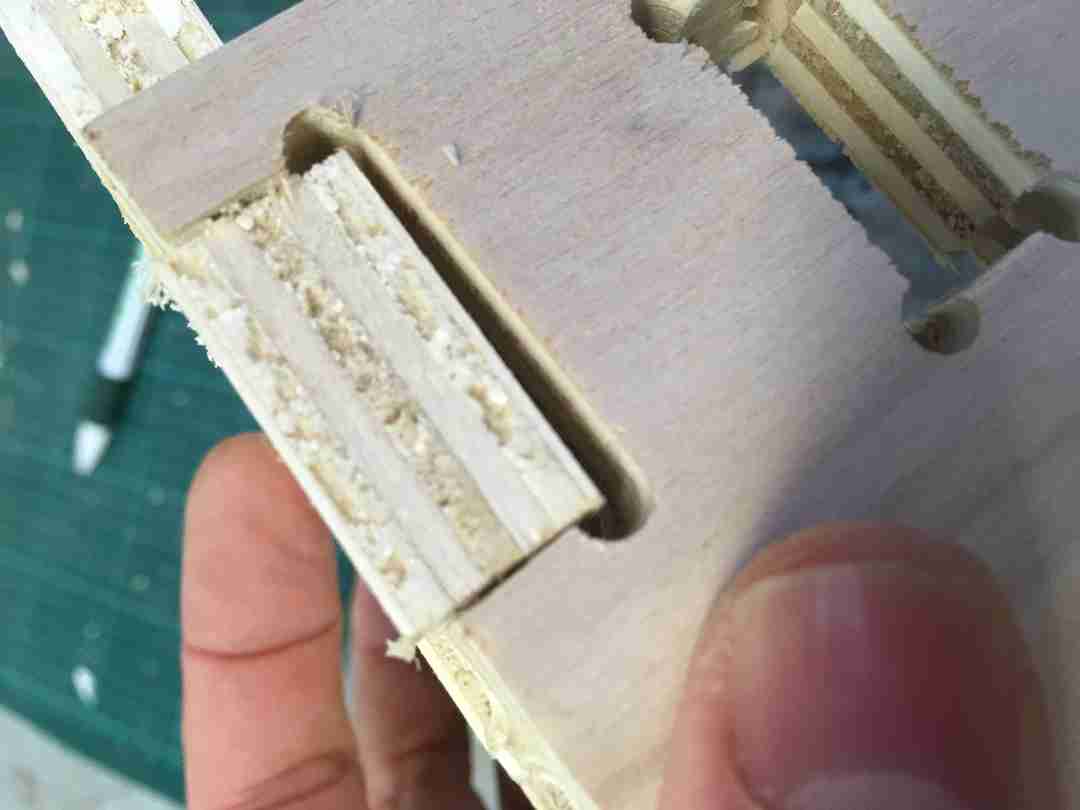 |
Finally, I was so happy about my clip tennon working I ran to show it to Andre who immediately went to unclip it, and, crack. That was that. Nice one Andre! :)
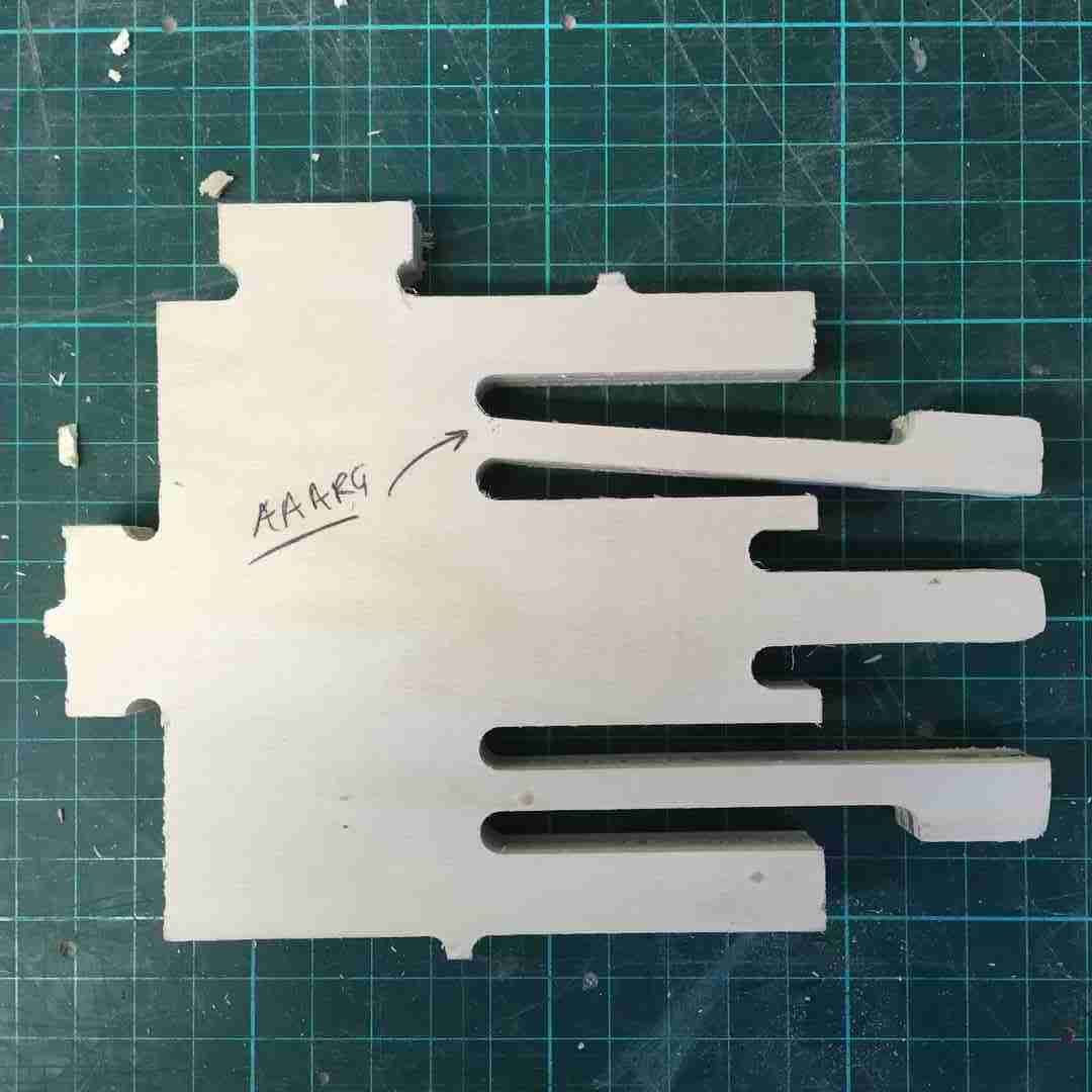
In truth, as Martin our esteemed Lab technician pointed out, clip tenons are really only fit for much stronger materials. However, I was resolute in making one work for our shitty plywood, as I wanted a box that I could assemble and disassemble for my FabVAWT. Back to the design board.
My BIG FabVawt Base
 |
 |
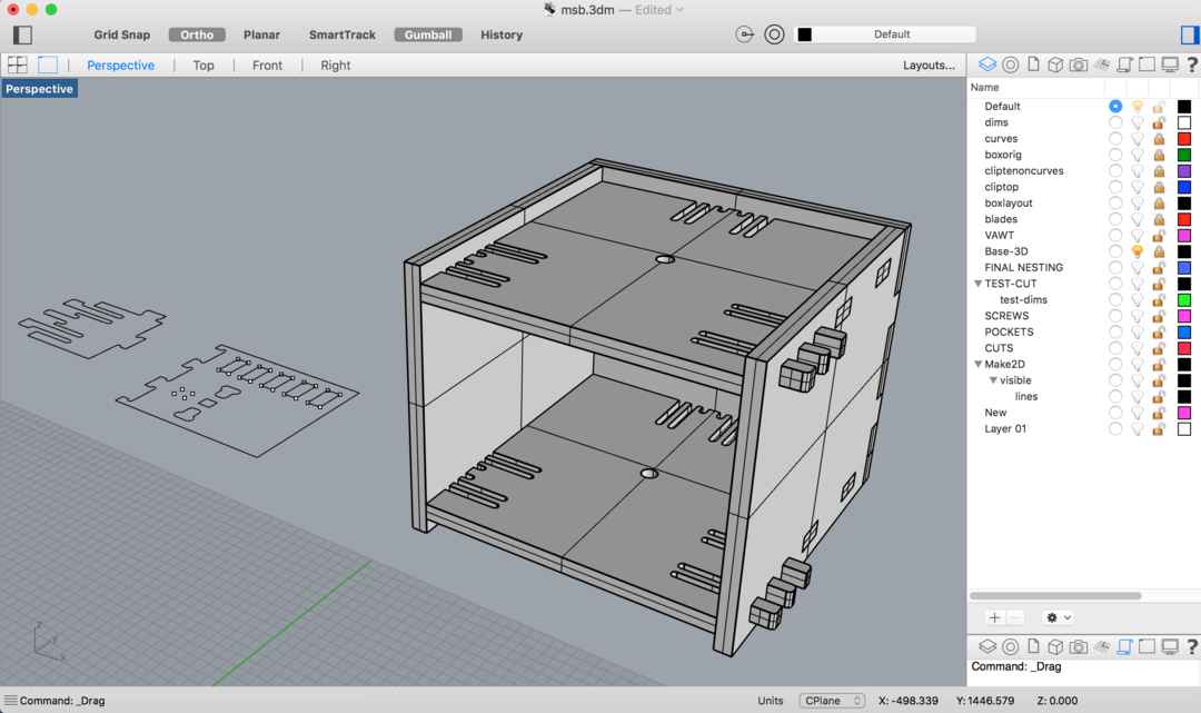
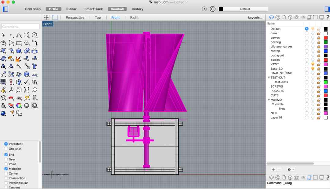
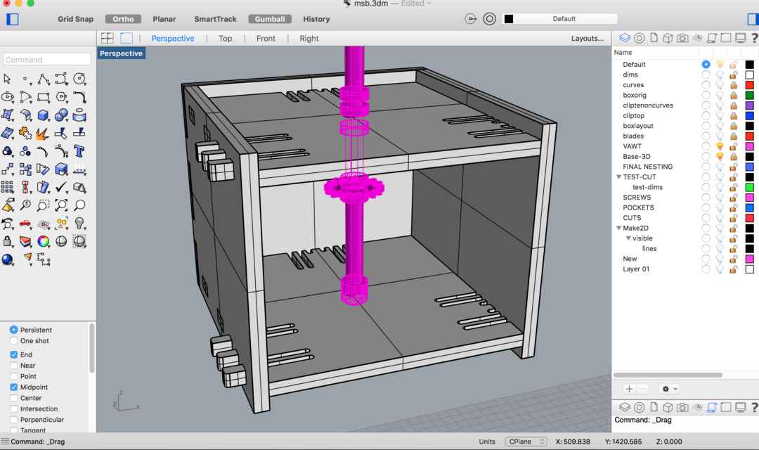
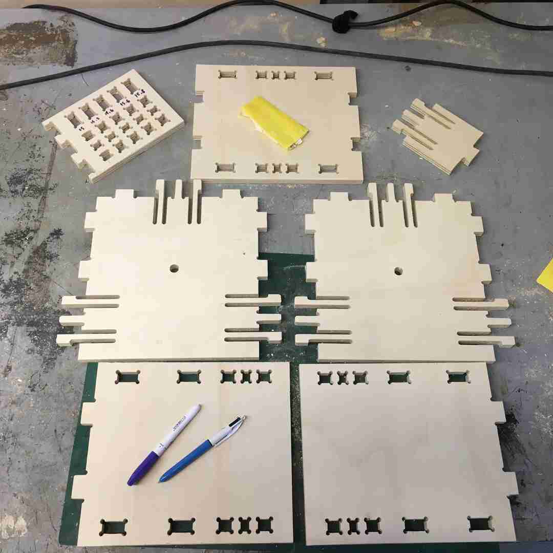
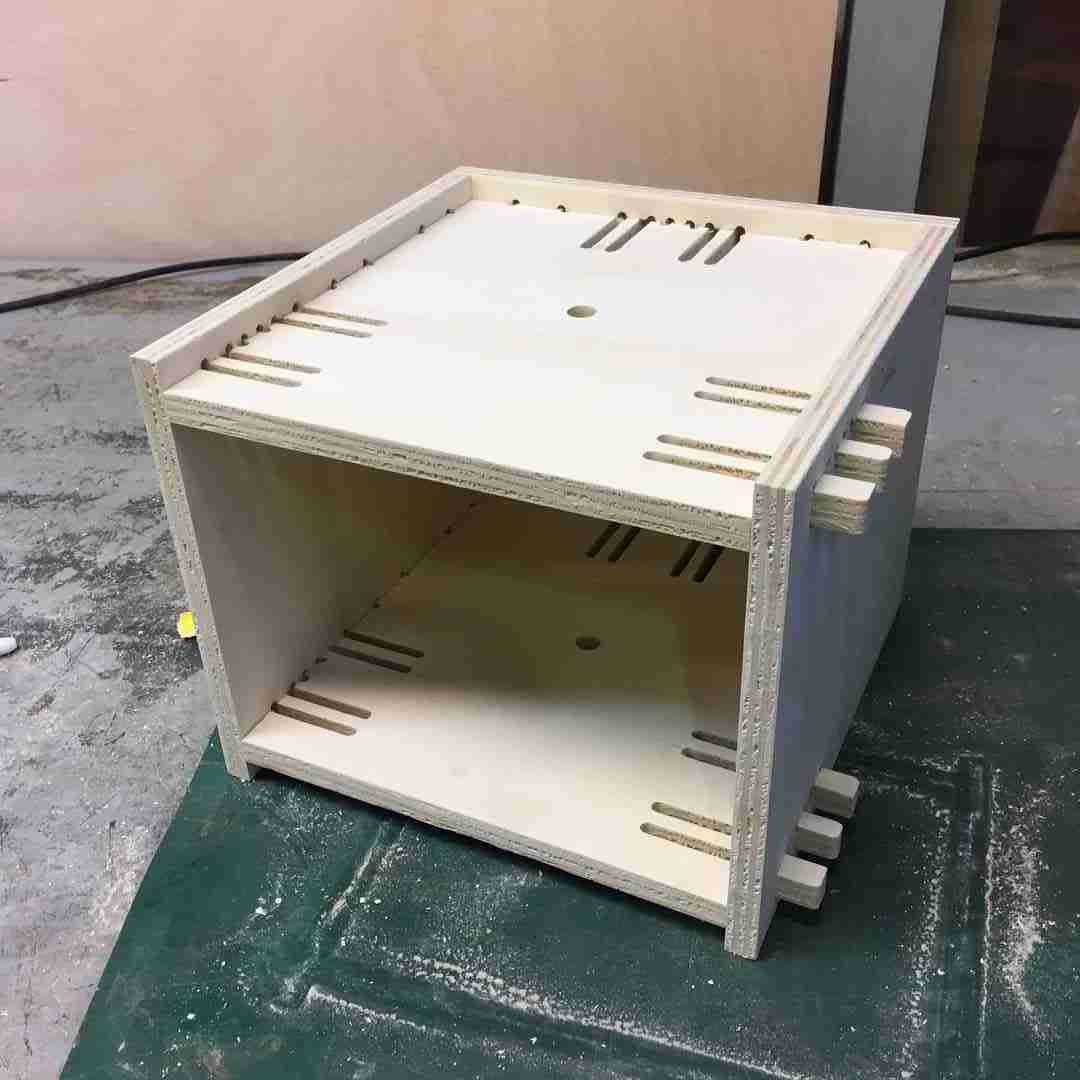
For my make something BiG I wanted to CNC the base to start testing my FABVawt, which is basically a solid box, with one open side so I can access the generator.
I designed the box in Rhino where I spent a significant amount of time refining that clip tenon joint. As you can see I struggled with the right tolerances, where my first test cut snapped. I went back and recreated the joints to be much thicker, baring in mind the tool diameter of course.
Here you can see it with the shaft and gear box.
Close up
Nesting
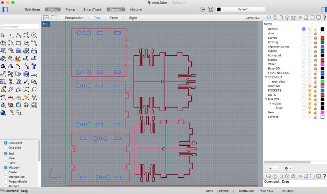
I decided I needed to make some better test cuts before I committed to the whole job, and needlessly wasted a bunch of valuable material.
CAM
For the CAM strategy I basically did the same 2axis strategy as outlined above. Basically it went like this:
- Engraving to mill my dog bones (board was already fastened to the sacrificial layer of the machine)
- Pocketing to create the pressfit and centre axis holes.
- Profiling to do the outer cut, with bridges manually placed using regions.
I used the same feeds and speeds settings because I knew this worked.
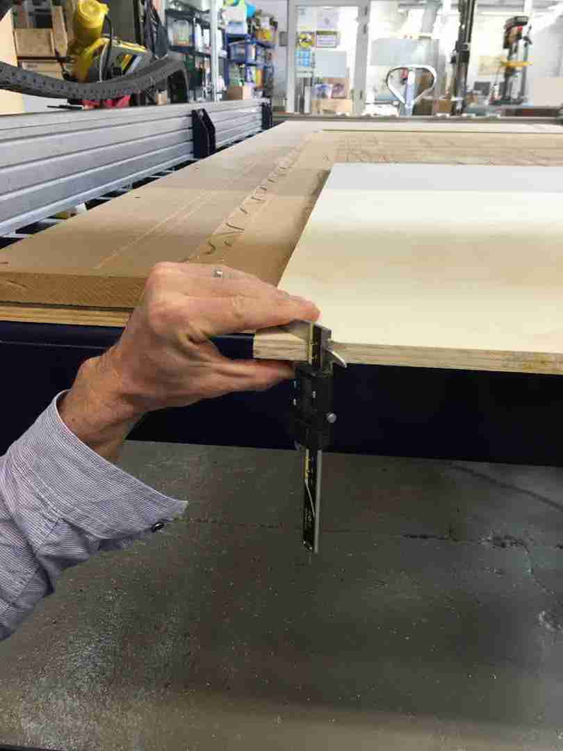
I wasn’t too happy with my clip tenon tolerances so decided to try this again. This time a 0.2 tolerance difference. First off, measure twice and set my axes:
 |
 |
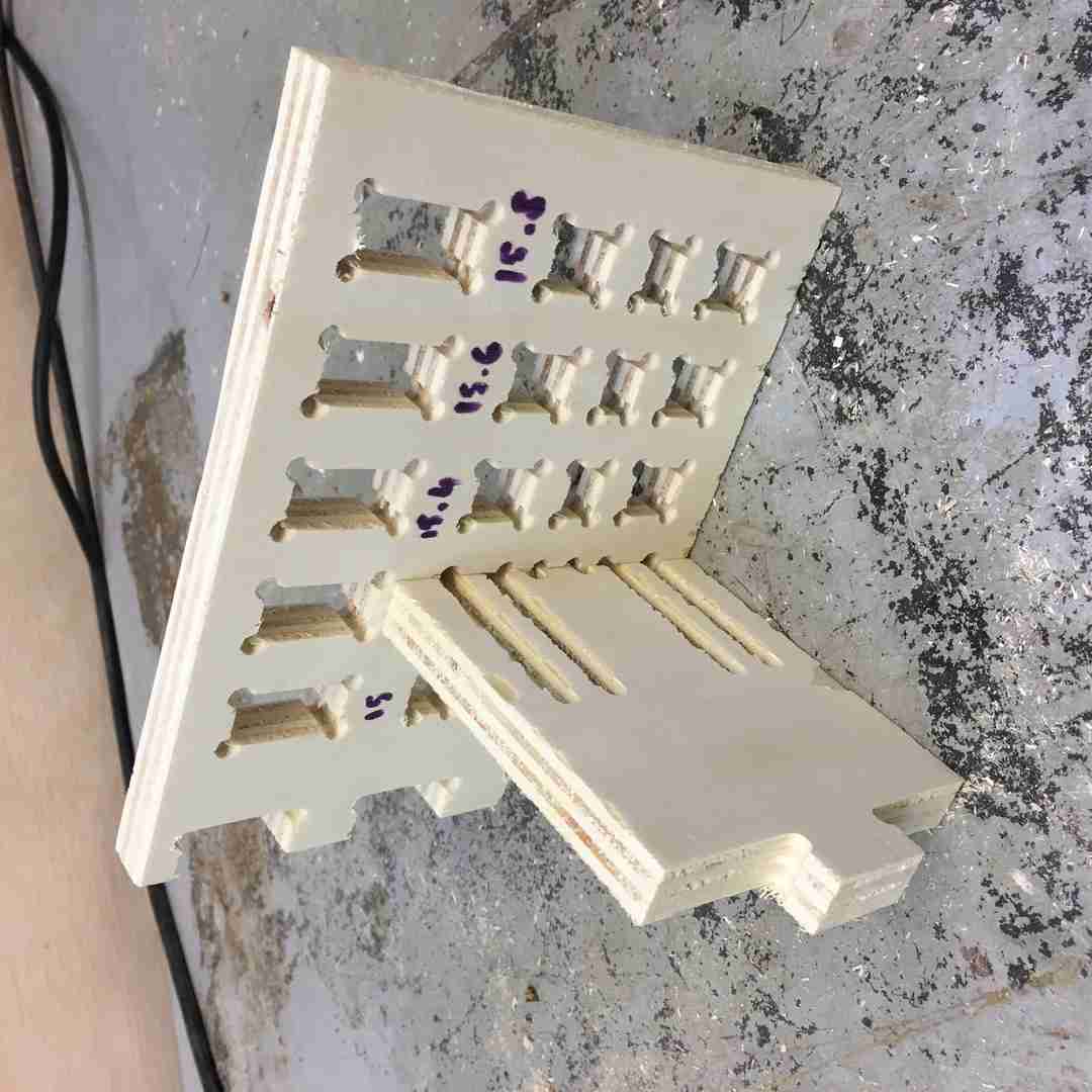
Ran my test cuts again, much better results:
 |
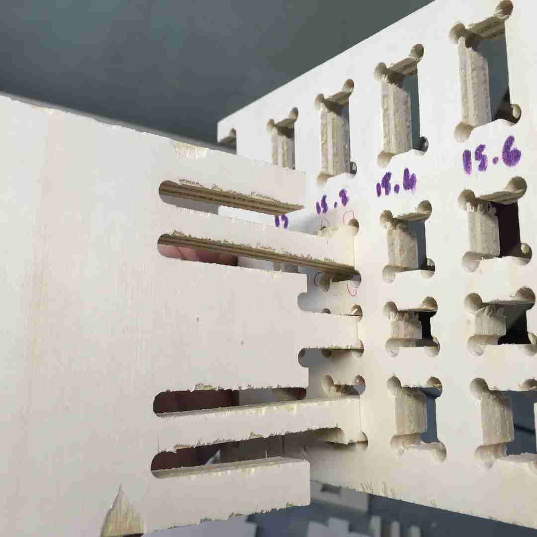 |
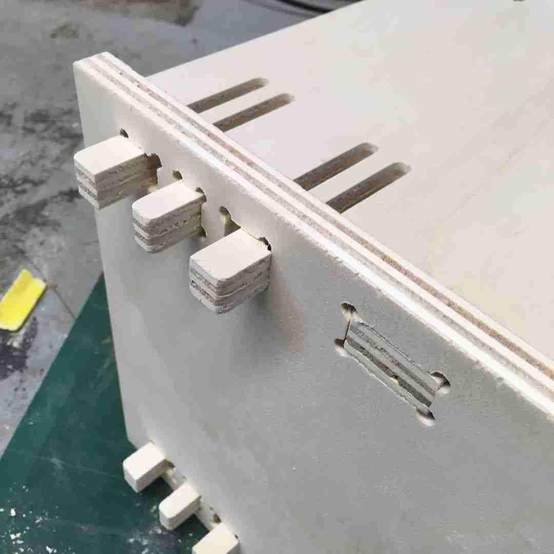
The clip is much sturdier now I increased it’s leg thickness, and still has the required bend to fit into the pocket. As you can see 15.2 (Here using 15mm thick plywood) was my perfect fit. And it still hasn’t broken yet :)
 |
 |
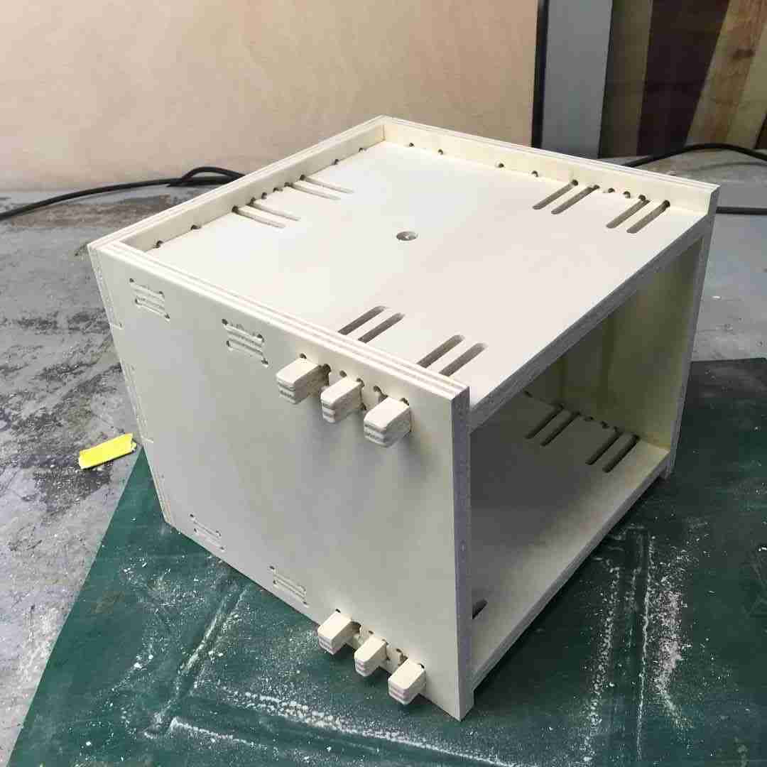
I was very happy with my test cuts, so now after doing some quick modifications to my pocket holes, it was time to mill my box.
The Final Cut
 |
 |
Conclusions
CNC milling is a lot of fun! There is a lot to learn in terms of CAM strategies, and I would love to get into some 3D surface milling. Here we have have only been milling 2D surface strategies, albeit to make 3d objects. What I mainly learnt, is that although my clip tenon works a lot sturdier now, the reality is my box isn’t that simple to take apart, so breaking is really easy. Stick to easy joints next time. But It was worth it to learn about kerf and tolerances.
You can download all my design files for week 8 from my Gitlab repository.