Prototype
Here I share my progress building my first prototype wind turbine. I have used various class assignments such as 3d printing (generator/wings), the Make Something Big assignment (housing), molding and casting (stator core) and electronics to model my FabVAWT and generator.
First there was a box
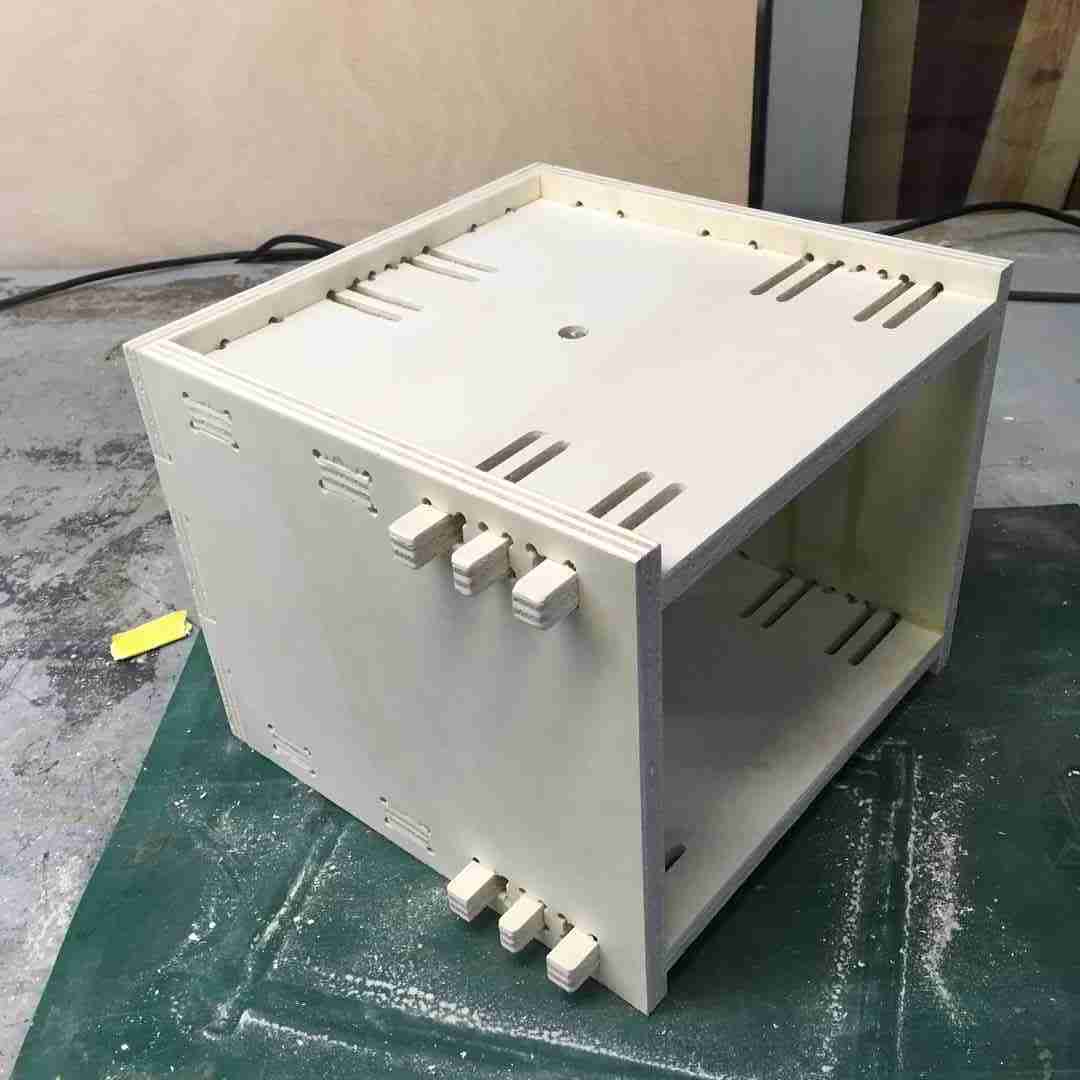
For the housing, I designed a box that I could easily assemble and disassemble as the housing/base for my wind turbine. Thee choice has three advantages:
- I wanted the axis to have 2 points of rotation, the top surface aligns it with a brass sleeve bearing in which it rotates freely but keeping straight while the weight rested on the bottom platform where it is held by a shaft collar that turns on a radial axis ball bearing.
- I wanted the box to be open on one face so I could access the parts, bearings and generator components easily.
- To reduce wobble, I decided to use clip-tenon joints (not ideal in retrospect but hey) to hold the box tightly in place without screws, while also making it easy to disassemble.
Discovering, Designing and 3d printing generators
While I was initially planning to reverse twerk a brushless motor to blinky a few LEDs, I got a little obsessed exploring and test various examples of 3d printed generators/alternators that I found online.
With the now improving efficiency and affordability of 3D printing, i noticed lots of people are interested in prototyping and experimenting with small scale power generation and motor electronics. Though with 30 Watts out of a few turns, this hand-cranked beast ain’t exactly small. While wind gurus like Hugh Piggot and The Backshed have been long been pushing OpenSource green power and off-grid power systems on the web, there are now numerous examples of model generators and motors on Thingyverse and Instructables. But due credit to the model aircraft aficionados and Christopher Laimer for pushing the boundaries of 3d printing in this domain.
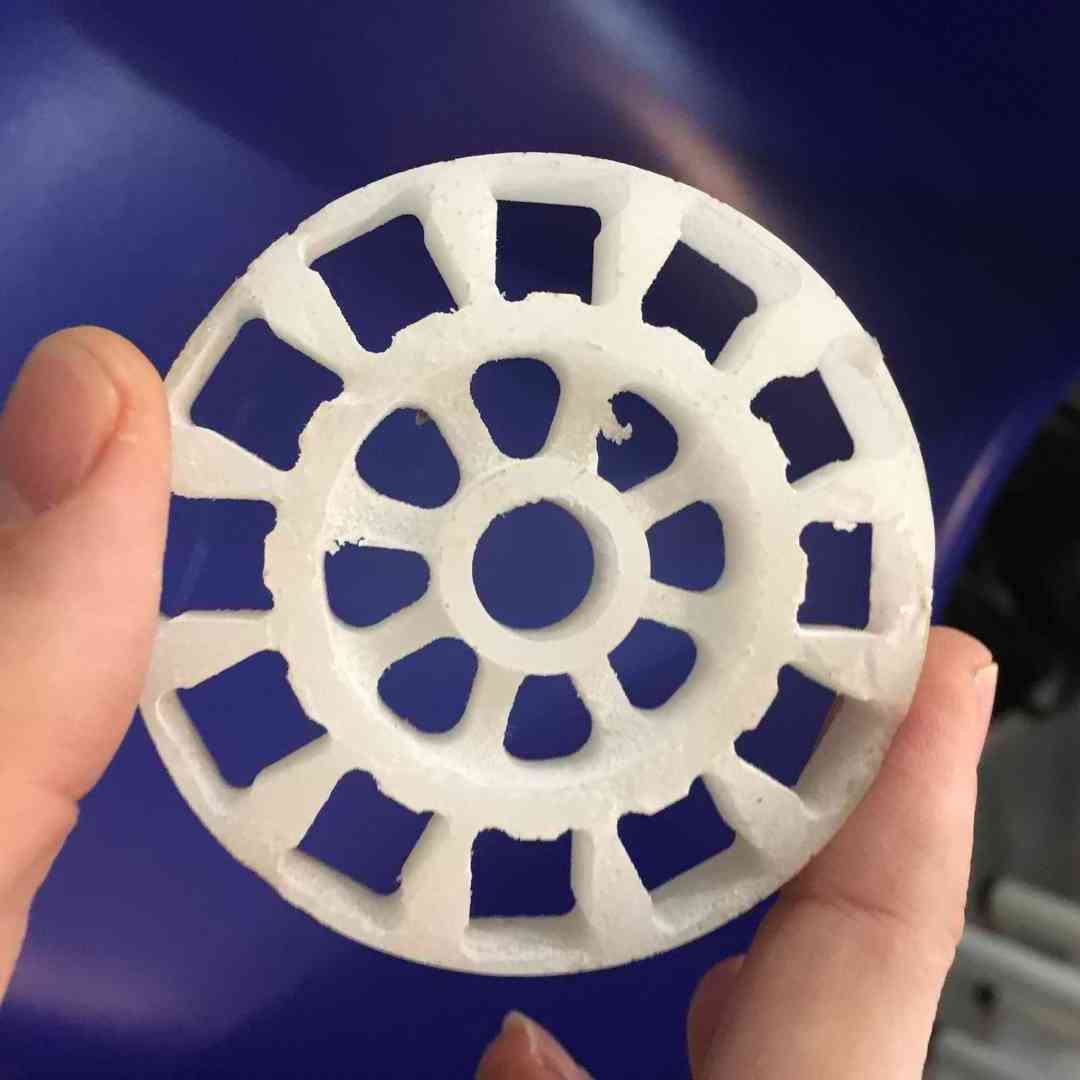
Molding and casting a rotor
Here is the design and the final casting of my rotor I did on week 10. Although I find molding and casting super interesting, this was a bit of a fail. For one there are quite a few design constraints imposed by using 3mm toolbits that require dogbones at right angles (see below) and my original idea of metal casting this component to increase the magnetic flux requires a little more practice, and more sophisticated metal casting methods. In any case this was the result I got with a quickform plastic cast:
 |
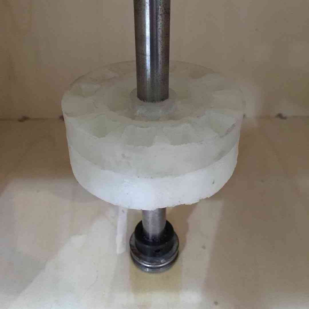 |
In the end I actually 3d printed the same design to compare. This is actually a lot better.
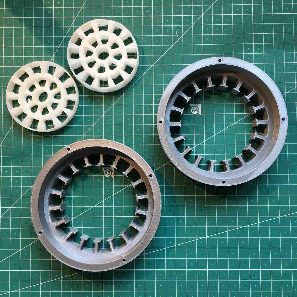
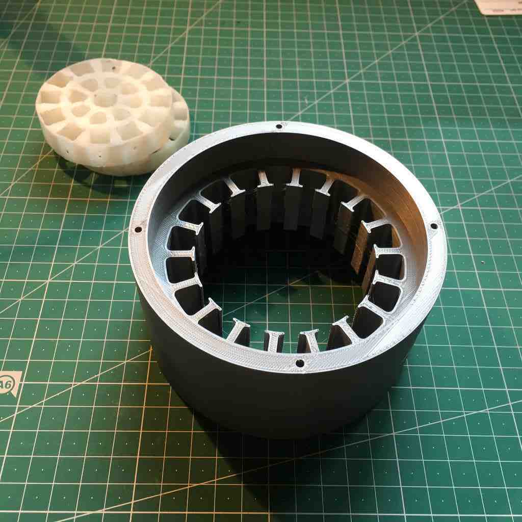
Designing and 3d printing my Stator
The stator is usually what it implies, a static part of the alternator which holds the conductive windings.
 |
 |
This is my first winding strategy, 100 turns of of 0.2 mm wire which we had in the Fablab, painstakingly tedious to wind by hand.
I had designed my stator core to house some 30x10x5mm neodymium magnets (locally sourced here). There are powerful and brittle magnets so watch out as they will crack and splinter if you let them snap together, and make sure to keep them away from your electronic devices.
These cost €1,25 a piece which is not cheap but they are good quality. As you can see I doubled them up to make (making a square 10x10mm width block), this was with the initial intention of twisting the polarity in a HallBach array arrangement to enhance the magnetic flux. For my first trial I just kept my poles switching north to south.
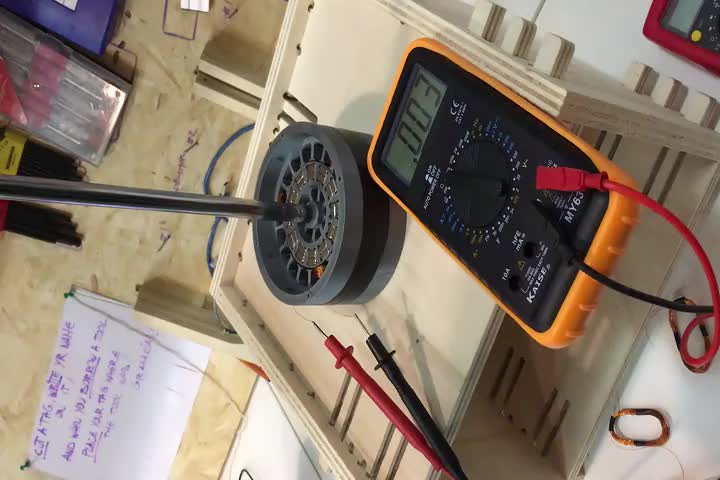
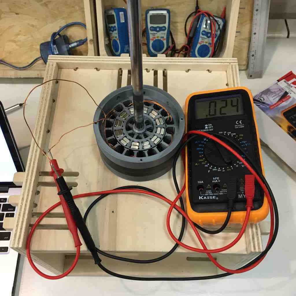
Here I tested by proto-alternator using the multimeter, as you can see I am getting close to 1.5 volts and 114 milliamps with just some hand spinning and only one phase of coils. This is reassuring. (Note, I think i’m measuring the amps wrong here!)
Winding strategies
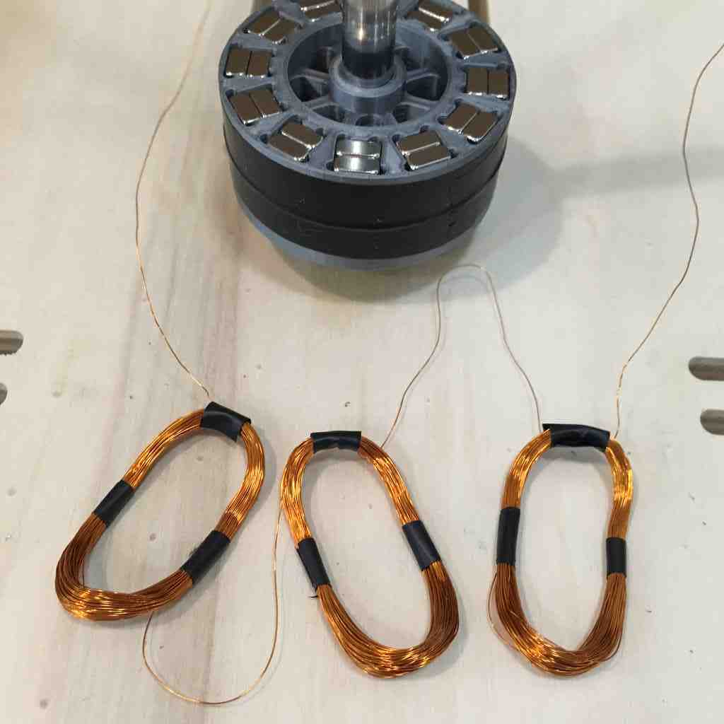
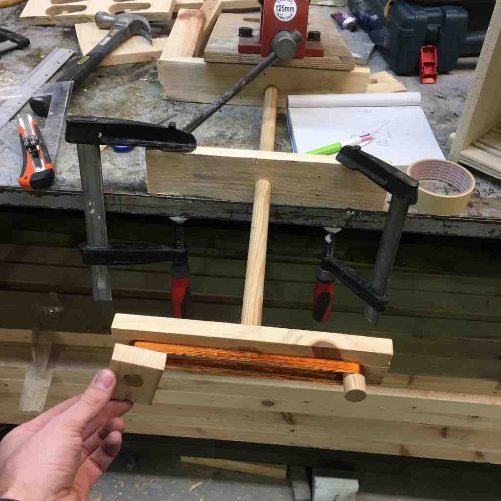
I decided to try a different winding strategy for my 3 phase alternator, and here big shout out to Caleb Engineering who thanks to some meticulous testing and documentation, really helped me make sense of this process. For this I copied Caleb’s rapid prototyping winder.
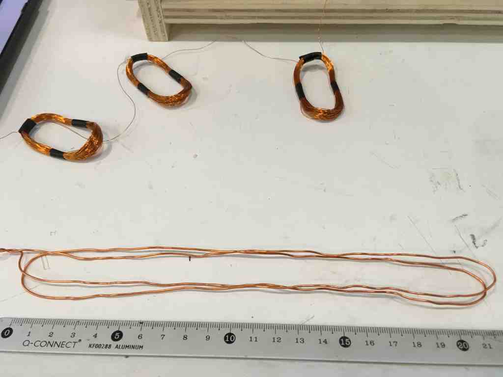
This is basically one much larger coil that I can bend three-fold into my stator slots. The two advantages of this strategy are:
-
It’s easy to wind, if Michel doesn’t keep interrupting your counts!
-
It’s easy to set and remove my coils if I have to should the design not work without wasting valuable wire.
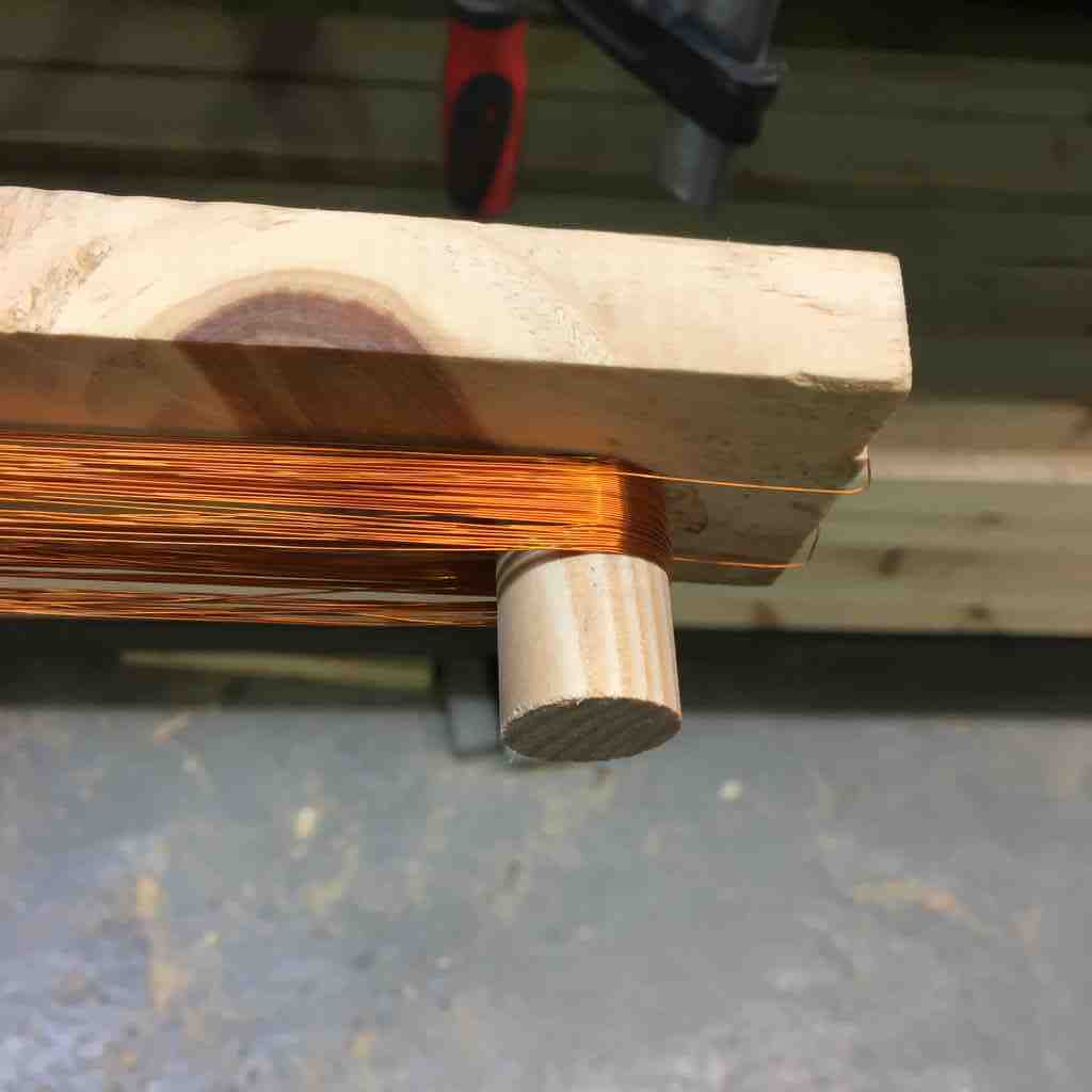
Here below I’m trying this out first with some 1mm thick wire to measure out how it will fit. In fact, how about a winding machine which count’s turns anyone?
 |
 |
Testing that this actually works:
And here the high-tech quick assembly coil winder. For this test I was going with 60 turns each of 0.2 mm wire.
 |
 |
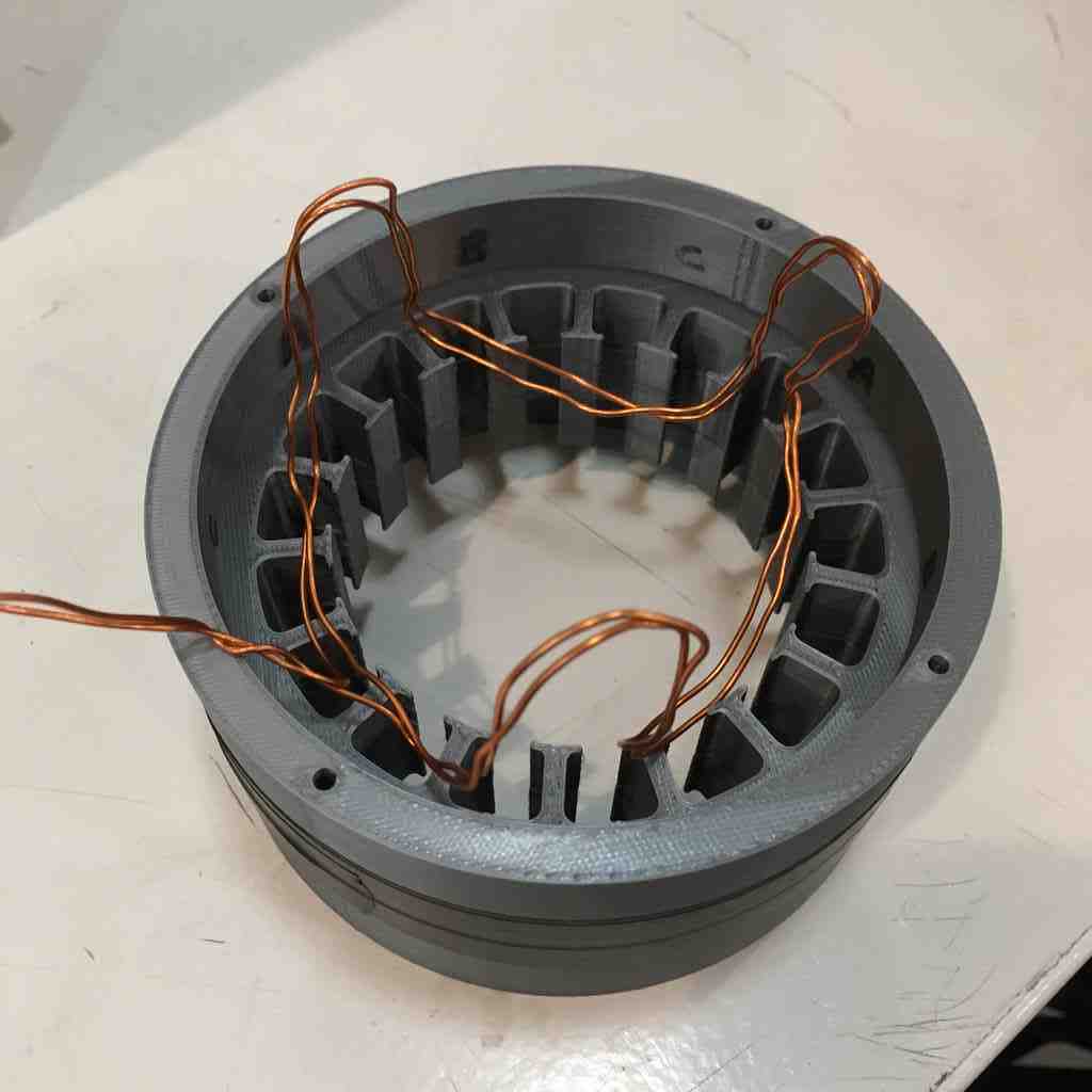
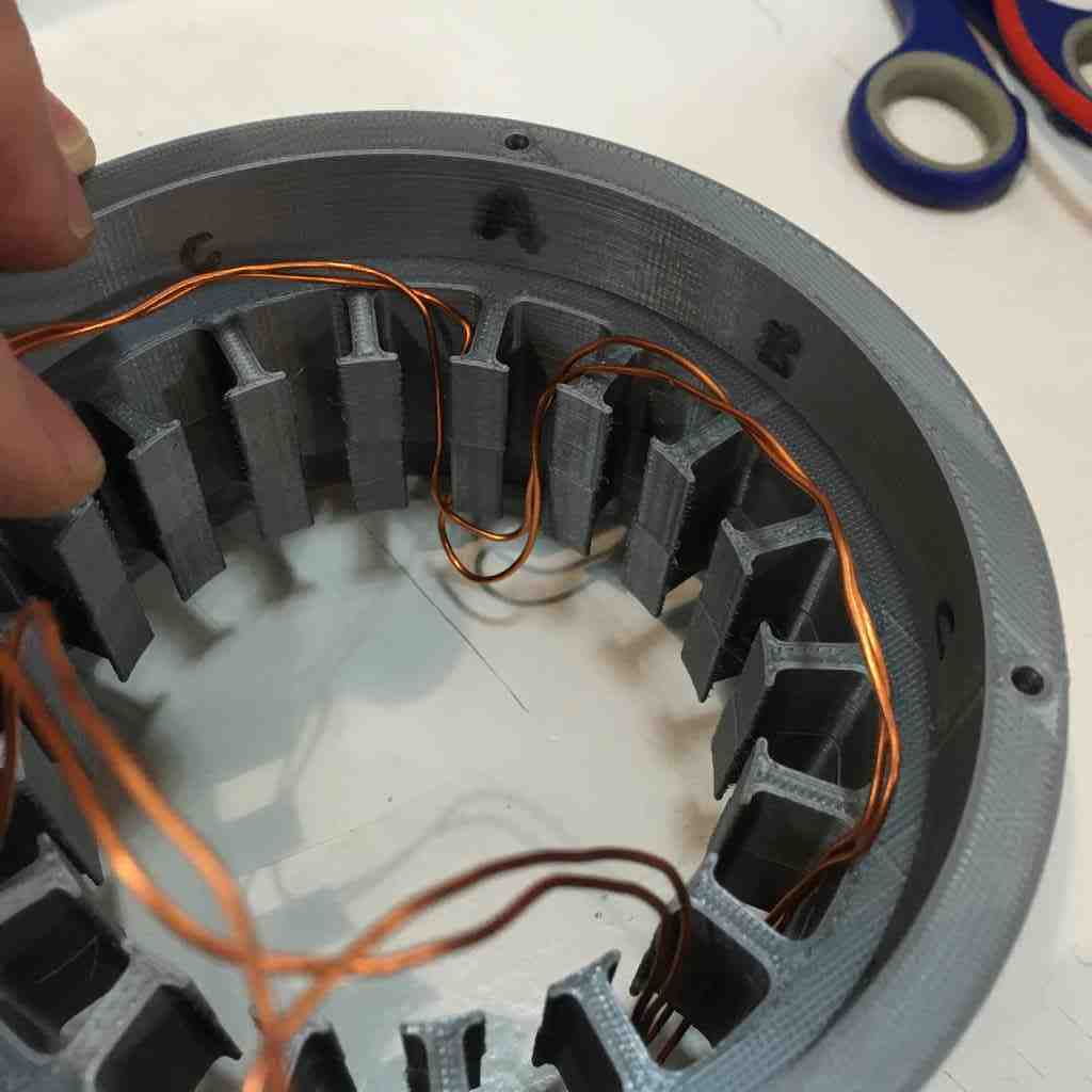
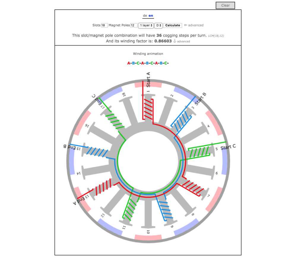
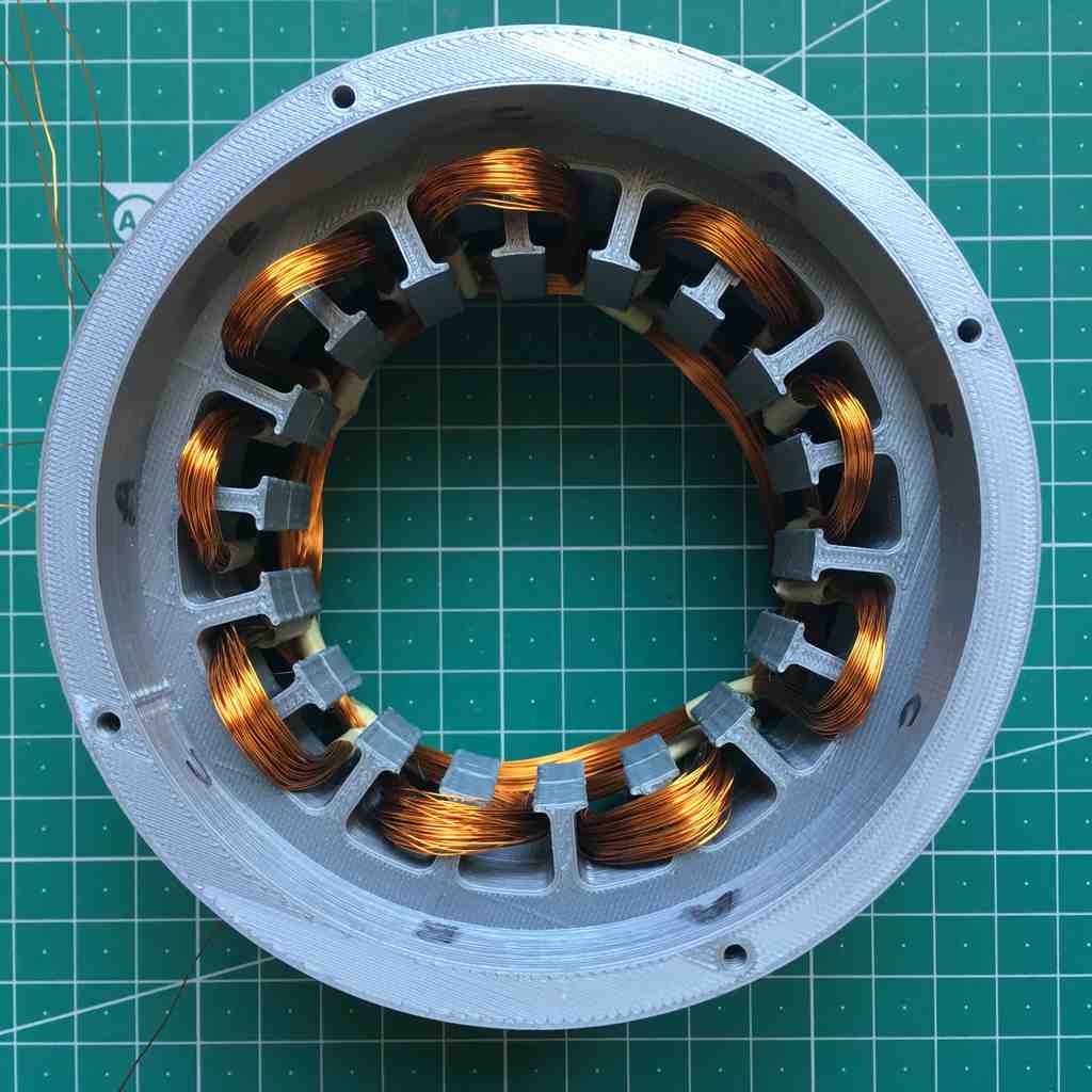
Below you can see once the coils are in place. For winding schemes, this is quite a complex subject but I was helped no end by bavariadriect who specialise in homebuilt electric motors. The concept is the same, as you can see below, here is my winding scheme using 18 slots with 12 magnets. For a three phase alternator your slots and poles have to be divisible by three to be balanced.
 |
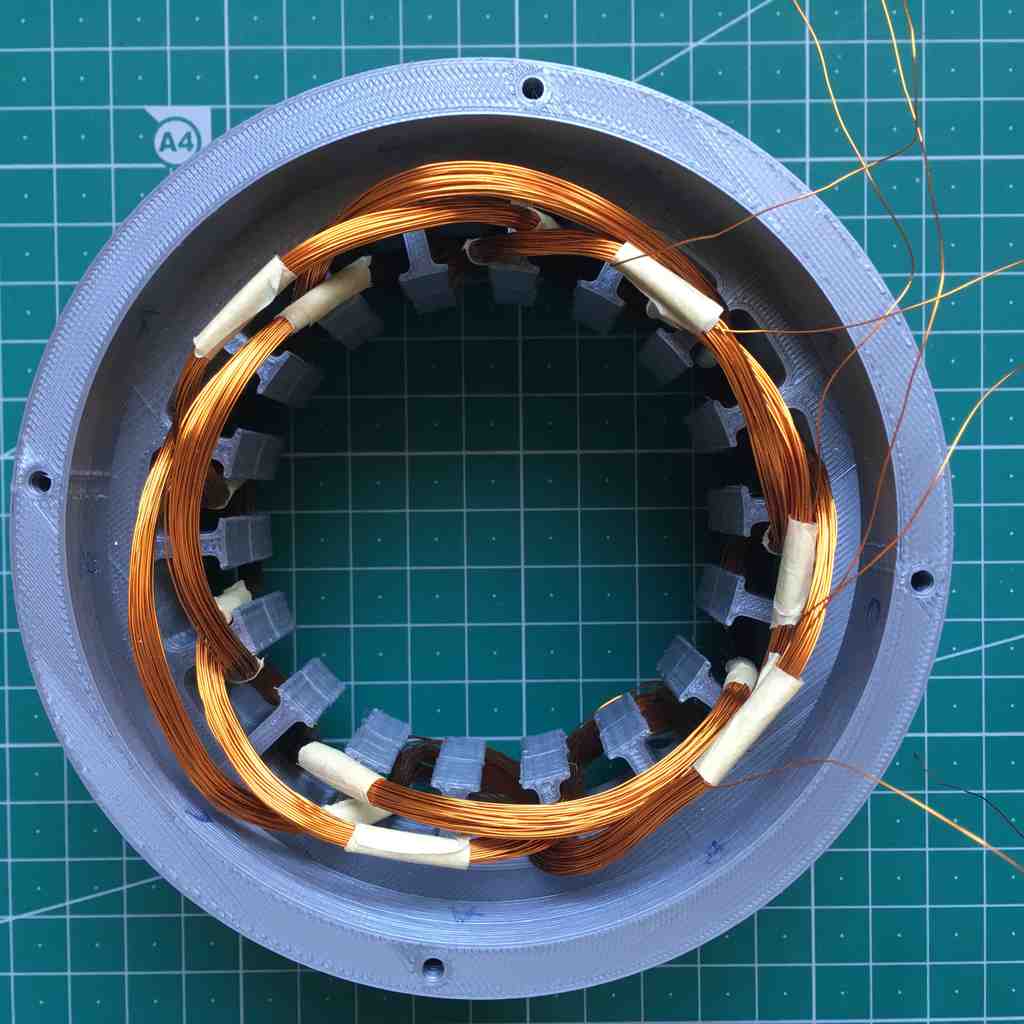 |
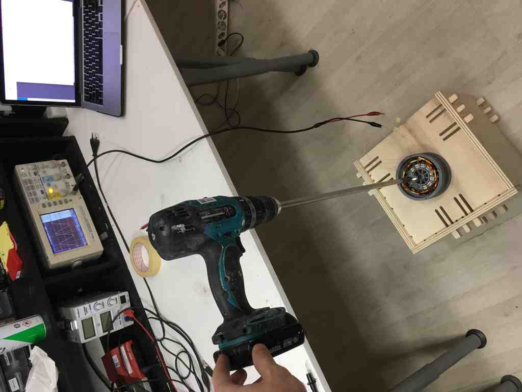
Then I tested each of the ins and outs of each “phase” - remembering to remove the insulation from the wire this time! Then I connected and soldered all the in’s together, and tested each “out” phase pair on the oscilloscope. For this I found a handy cordless drill:
And here below you can see my readings on the oscilloscope. This was my first time using one of these (and no one in our lab seems to remember how to use one) so it took some fiddling and figuring out. Electronics Club, as well as providing a no-nonsense run-down on basic beginner electronics, have a handy oscilloscope guide. This is one of the most useful tools in the trade. Together with a multimeter I highly recommend you take the time to learn to use one in the FabAcademy.
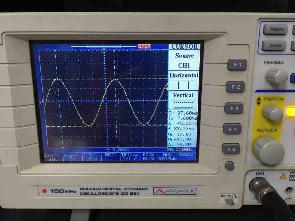
My first observation is that the phase wave has a nice shape to it, this is a good sine :)
Because I have 6 poles in my rotor (12 magnets witching sides) I have to take into account that I am getting 6 “waves” per revolution.
According to this reading I was getting 38.8 volts peak to peak at 22.12 Hertz, multiplied by six poles makes 132.7 Hz per second. Hertz is the SI base unit of frequency defined as one cycle per second. So to calculate revolutions per minute we multiply by 60 which gives us 7,963 RPM.
…if the generator has 6 magnetic poles (6 north, 6 south for 12 magnets) so we must divide the frequency by 6, which gives us 3.68 (rotations per second) and x 60 = 221.2 RPM.
Our lab oscillator is quite an erratic little machine and I need to take time to familiarise myself with it’s inner workings to do more tests, and gage my power output. But first, in the spirit of spiral development, I had to move on and make sure this thing can actually spin in the wind. I needed some wings.
Designing my wing supports
I decided to use some 5 mm thick white acrylic that we have in the FabLab to make wing supports. But I needed to figure out a way to fasten them to the shaft in a way for it to resist a high torque.
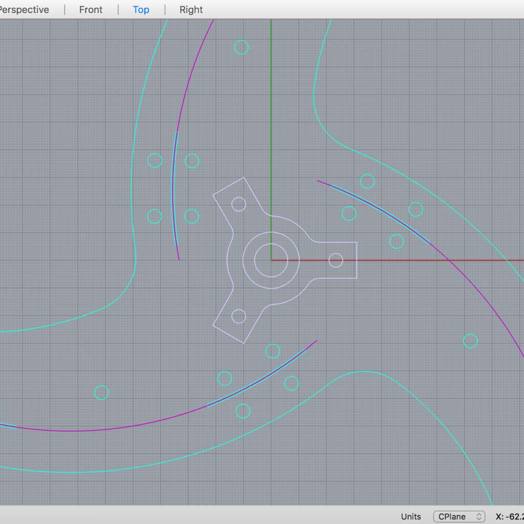
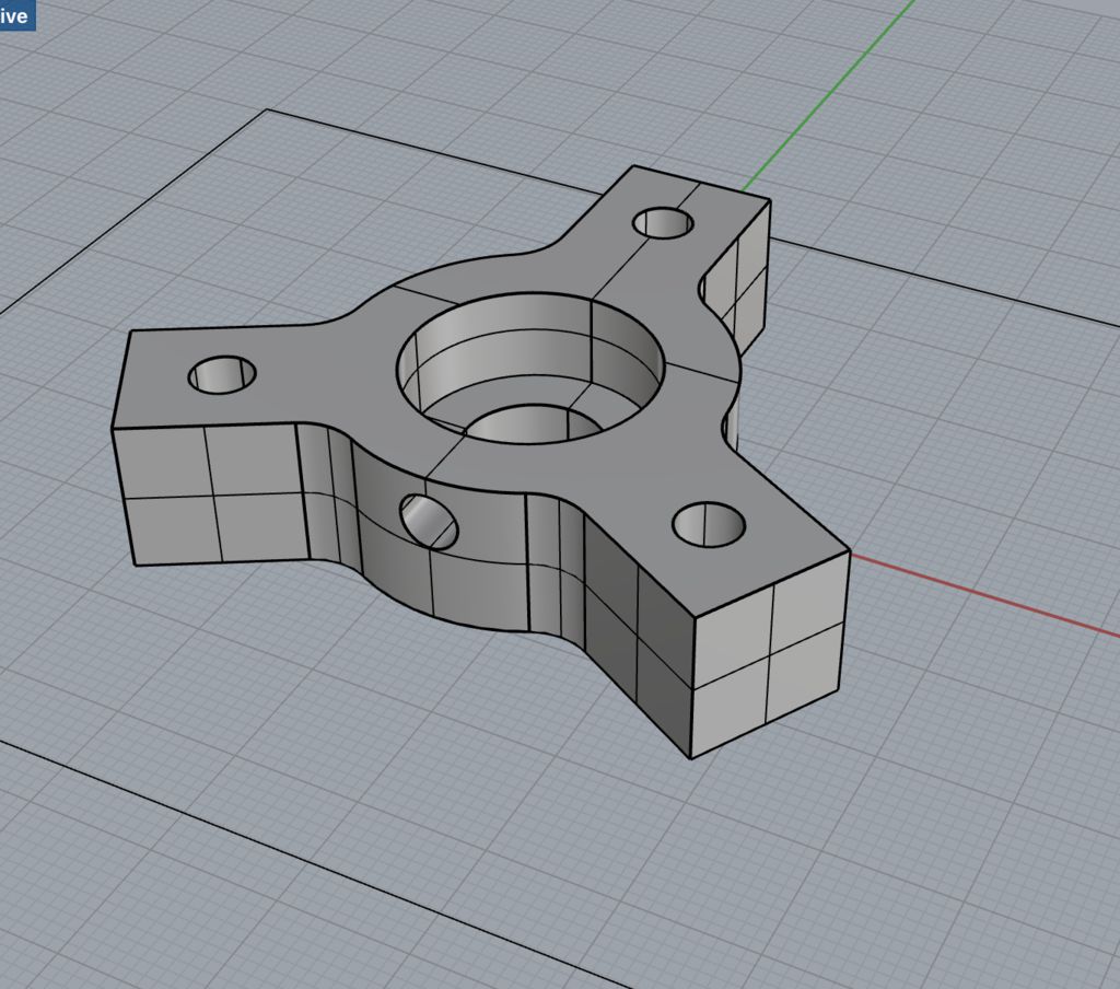
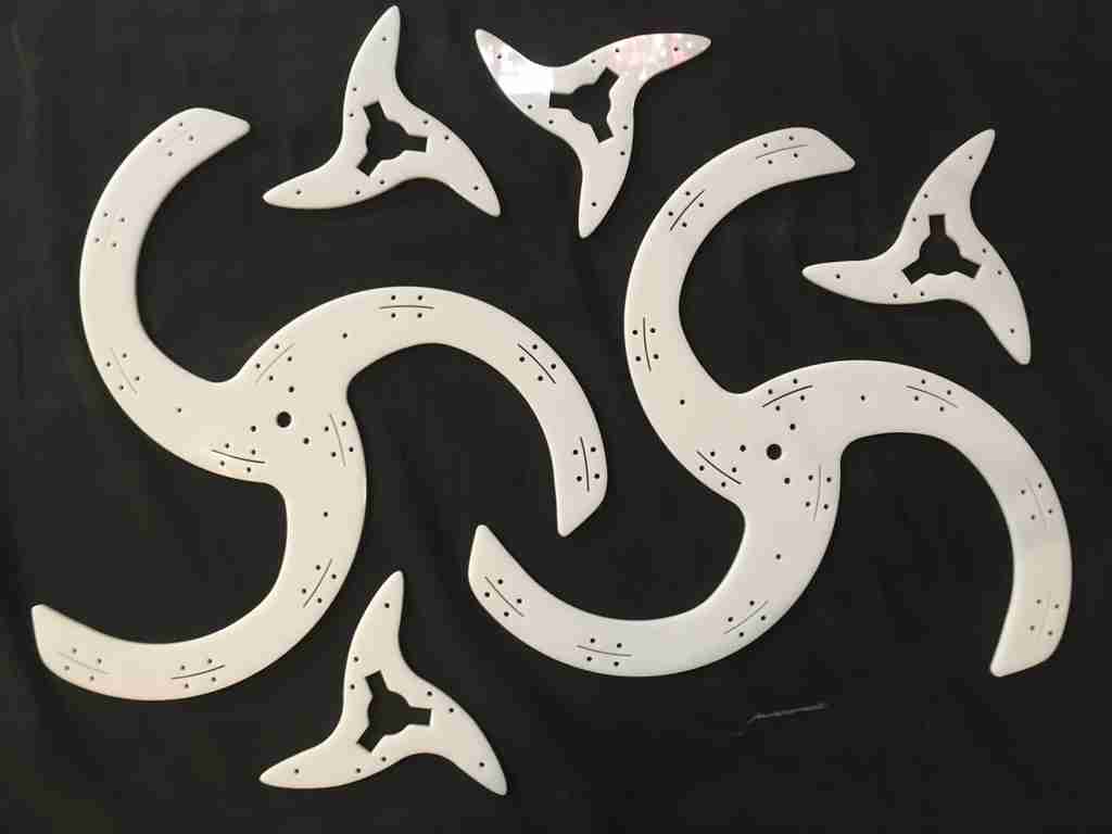
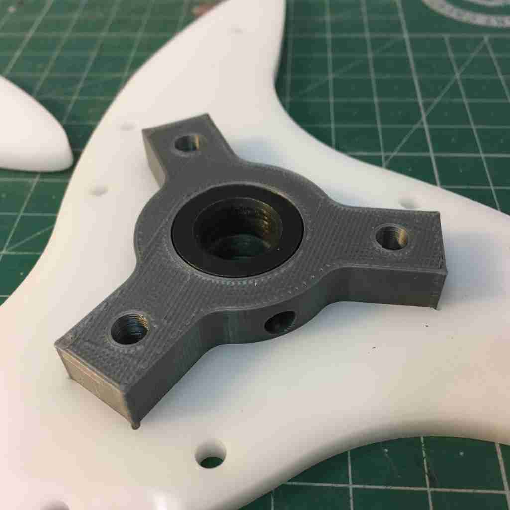
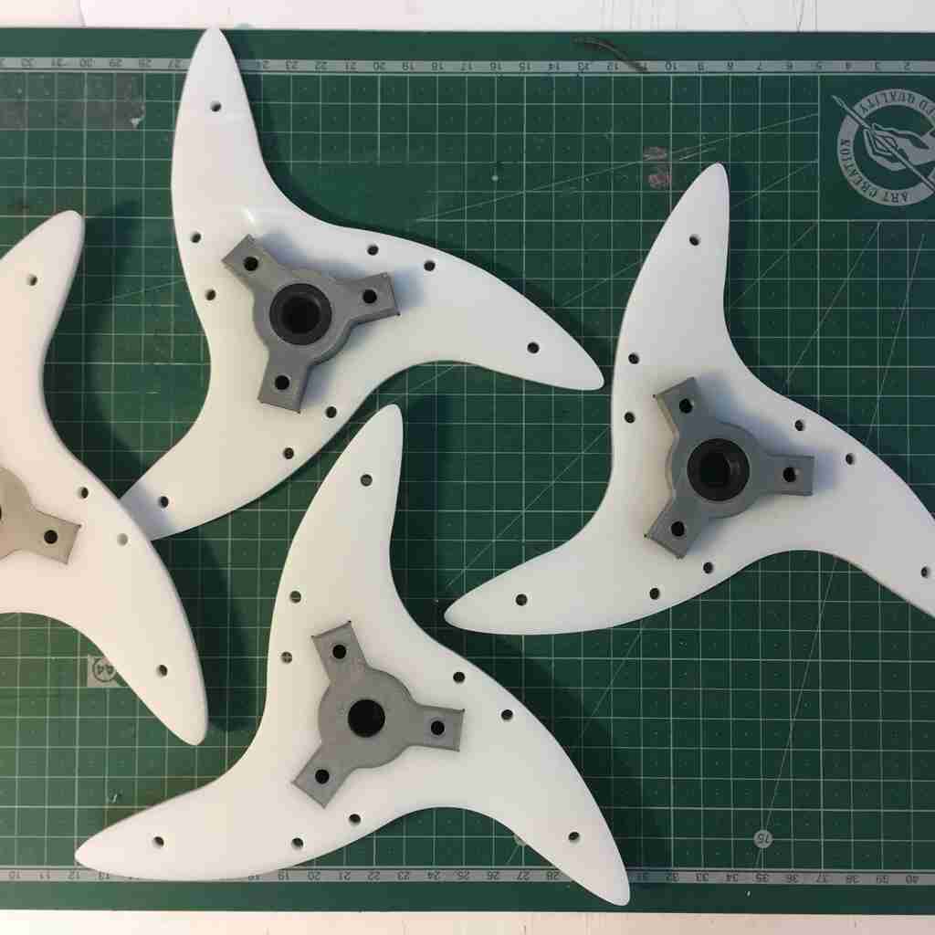
Here i used the same shaft collars as for the axial bearings below, but housing them in bigger 3d printed “twisters” that could be in turn fastened to acrylic blade supports sandwiched together in one triple decker wing support, making the the whole thing much more stable.
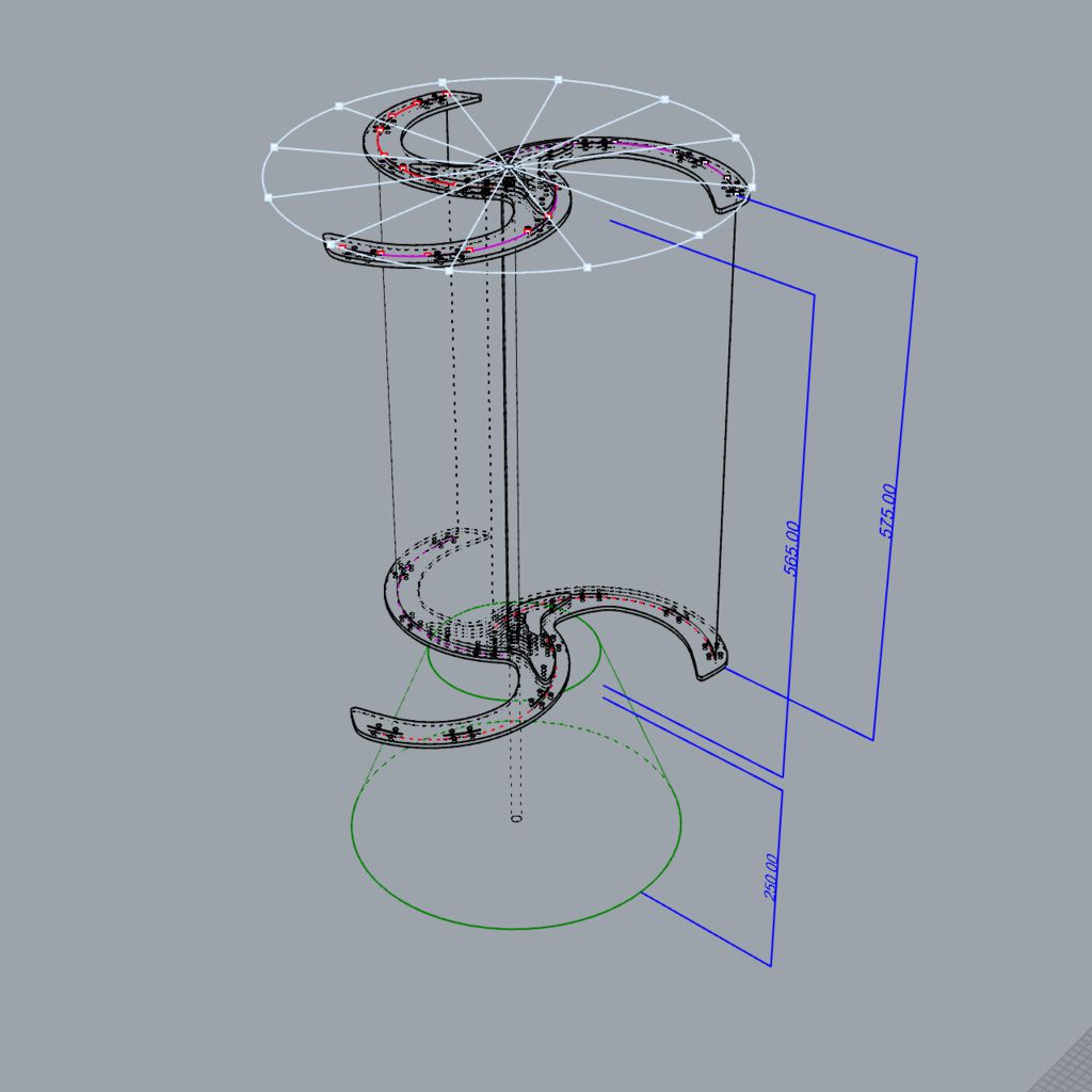
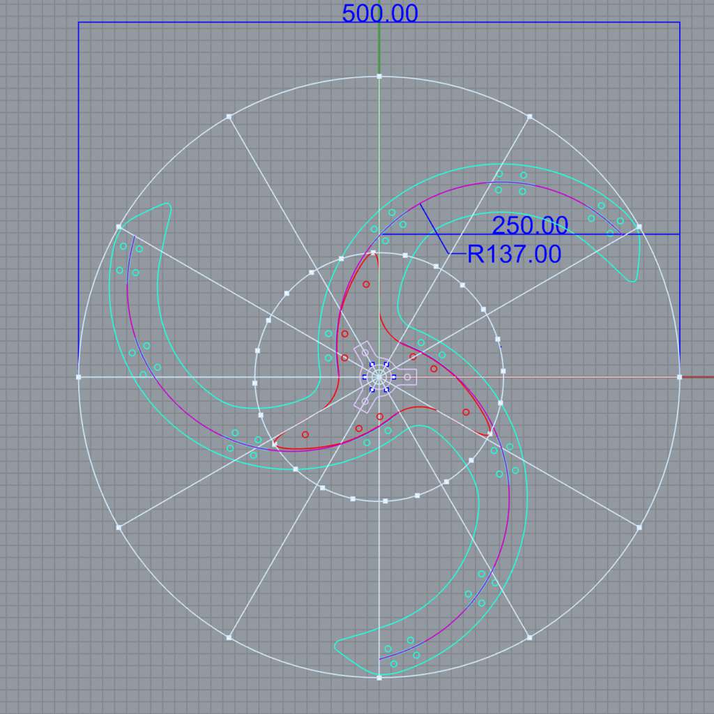
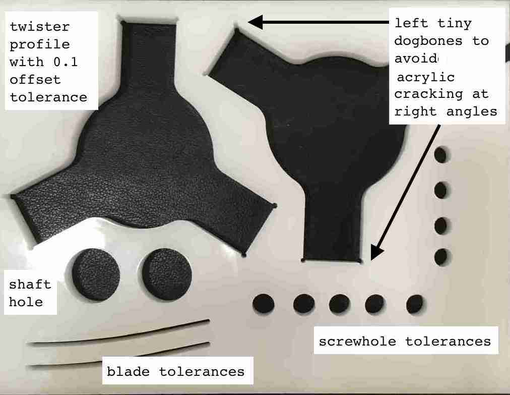
Below you can see the designs and dimensions, note my curve radius of 137. I would have liked to play around with different curve radii but that will have to be next phase. The dimensions were also in part dictated by the material we had available and the size of the laser cutter.
 |
 |
Test cuts and prints
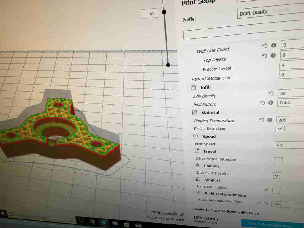
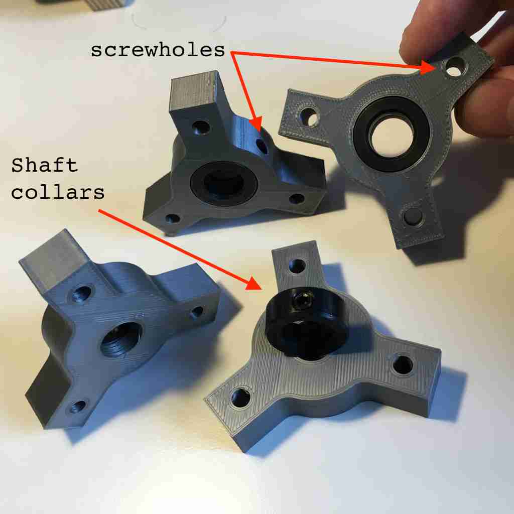
First came first, 3D printing my “twisters” which had to be house the 20 mm diameter shaft collars and also fit into the acyclic blade supports. I used a cubic infill pattern with 30 infill density, 3 wall line count and no supports as even the screw hold was sufficiently small and according to Miguel our 3D printing in-house genius this was not necessary.
 |
 |
After one failed print which didn’t stick to the bed, the rest came out pretty sweet. So I sent four to print at once which I happily left all night to finish. Here are the parts as I fitted them with the shaft collars. Note that I used zero tolerances so that the fit is more than snug.
Laser cutting
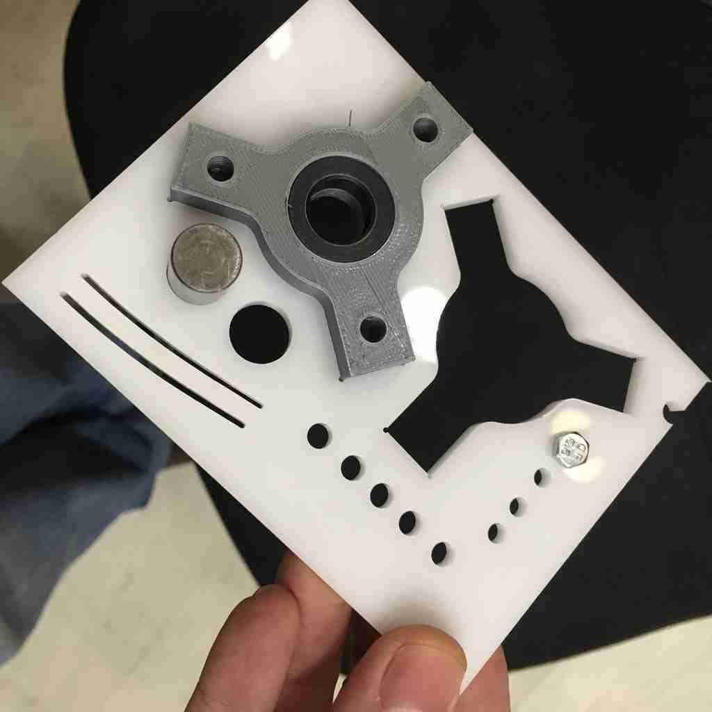
Here you can see my test cut with the acrylic using the Trotec 400. The rule of thumb in laser cutting, with organic materials we use a low frequency while with inorganic materials we use high frequency. Also we don’t want to have a too slow speed with acrylic or it tends to melt. After slowly incrementing the power I found the optimal cut settings of:
Power: 100
Speed: 0.60
Frequency: 25,000
 |
 |
 |
 |
Mounting wings
I have been contemplating the various material possibilities to use for my wings. One idea I had was to do make a composite wing in the wildcard week, another was to use 0.5mm aluminium flashing. Some sort of lightweight fabric is also a possibility but holding it in place will be tricky.
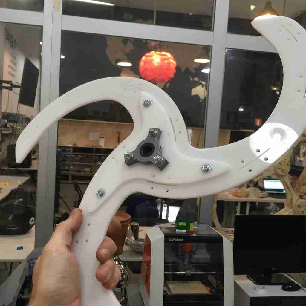
I realise now with all the screws in that the weight of my wing supports may be a problem so obviously the lighter weight the better. As a rapid prototype solution I decided to use some cheap 0.5mm thick polypropylene sheet to start with. These come for €3.90 for a 1050x750 sheet at hardware shop.
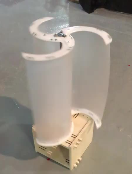
While I think polypropylene is ok to lasercut, i missed a little bit of the old cutter and scissor handicrafting so I ended up cutting out the wings myself without too much difficulty. What was more time consuming that I had figured was screwing them all together. But in the end I managed. Fast forward to my first (sans generator) fan test.
There she blows!!