CAD Design
As discussed earlier, Savonius type rotor is a drag-based wind turbine because it’s the drag component of the aerodynamic force that powers the Savonius turbine to rotate. We can estimate the torque, and mechanical power output of a Savonius rotor using a simplified model, thanks to the fantastic online math app Geogebra.
- Construction - diameter of the biggest circle
- Rotor - diameter of the rotor
- Gap - value in percentage, the gap between rotor and blade
- Blades - number of blades
- Direction - change the blade orientation
- Angle° - the angle of single blade °
- Rotate° - rotate the construction by given angle °
These are some initial sketches in Rhino I did in week 3:
 |
 |
Mechanical constraints
Some of the important considerations I found on my first design was actually understanding about the mechanical properties involved, in other words how was this thing going to spin.
For this I needed to brush up on some some Mechanics 101:
Torque
Torque is basically rotational force. Just as a linear force is a push or a pull, a torque can be thought of as a turning strength. Torque is how hard something is rotated. Torque = Force × Distance
This distance is also called the lever arm or moment arm, as if like above you were leveraging the spanner to screw a nut.
For the purposes of a wind turbine, torque is force multiplied by the perpendicular distance to the axis of rotation.
In drag design VAWTs the wind literally “pushes” the blades out of the way, so such turbines are characterised by slower rotational speeds but higher torque capabilities.
Friction
Friction occurs everywhere two surfaces are in contact with each other. It’s what makes door hinges squeaky and mechanisms noisy. High friction is sometimes a good thing when your mechanism interacts with the environment, such as the way friction allows your car tires to grip the road. However, friction is usually your enemy when it comes to making things move. It can rob your mechanism of power and decrease efficiency.
Finding my axis
After looking up and down various ferreterria shops for a suitable central axis shaft, with minimal success, out lab technician Martin suggested I use a 12mm precision steel shaft that was gathering rust in the junk pile. This used to belong to a 3d printer and was just what i needed.
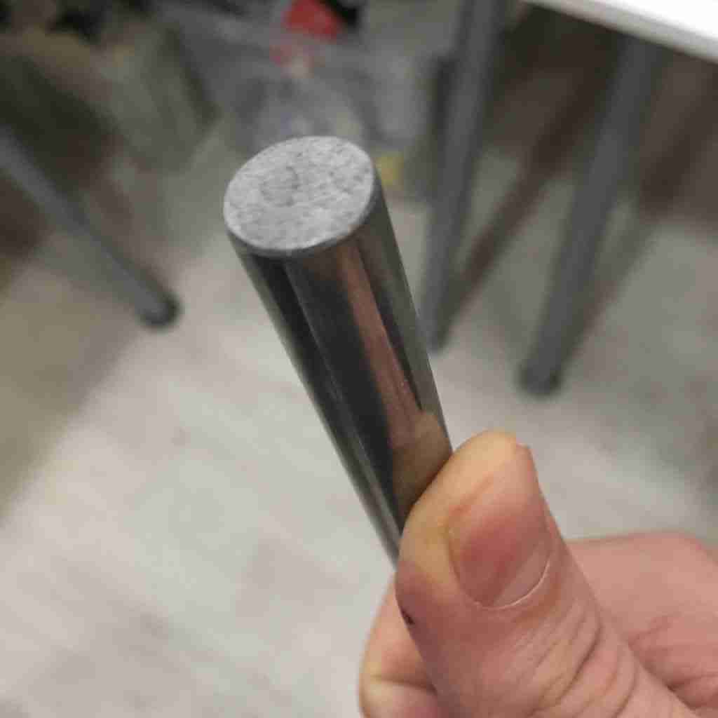
I used some steel wool and a bit of WD40 to remove the rust and it was as good as new. More than anything, it was dead straight and strong to carry the high torque.
Finding my bearings
I realised pretty early on I couldn’t really start designing without have a clue as to what components I was going to need, and their basic dimensions. Here I had some luck scavenging unused parts in the Fablab, and discovering the bearing oracle who lives down the road and donated bunch of used axial bearings to try out for nothing.
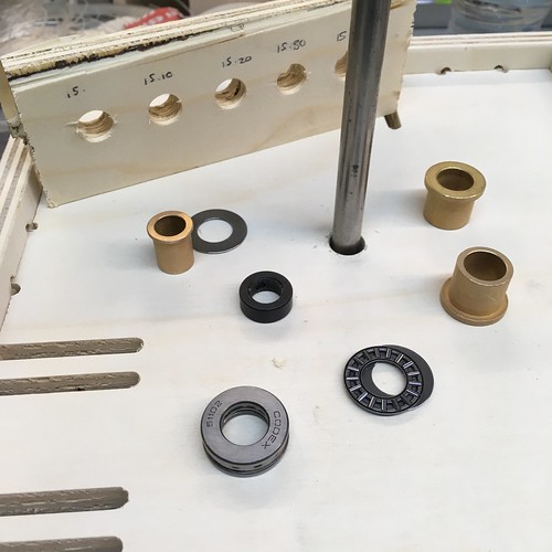
Radial and Axial Bearings
Bearings support a shaft or housing to permit their free motion on an axis of rotation. Load can be applied to bearings in either of two basic directions: radial and axial. Radial loads act at right angles to the shaft’s axis of rotation while Axial (thrust) acts parallel to the axis of rotation.
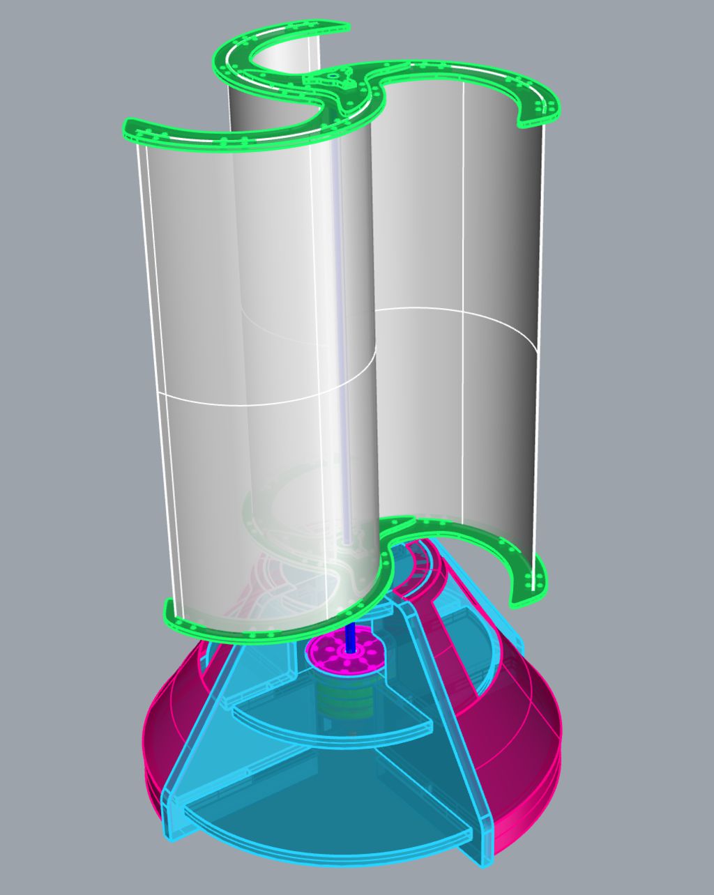
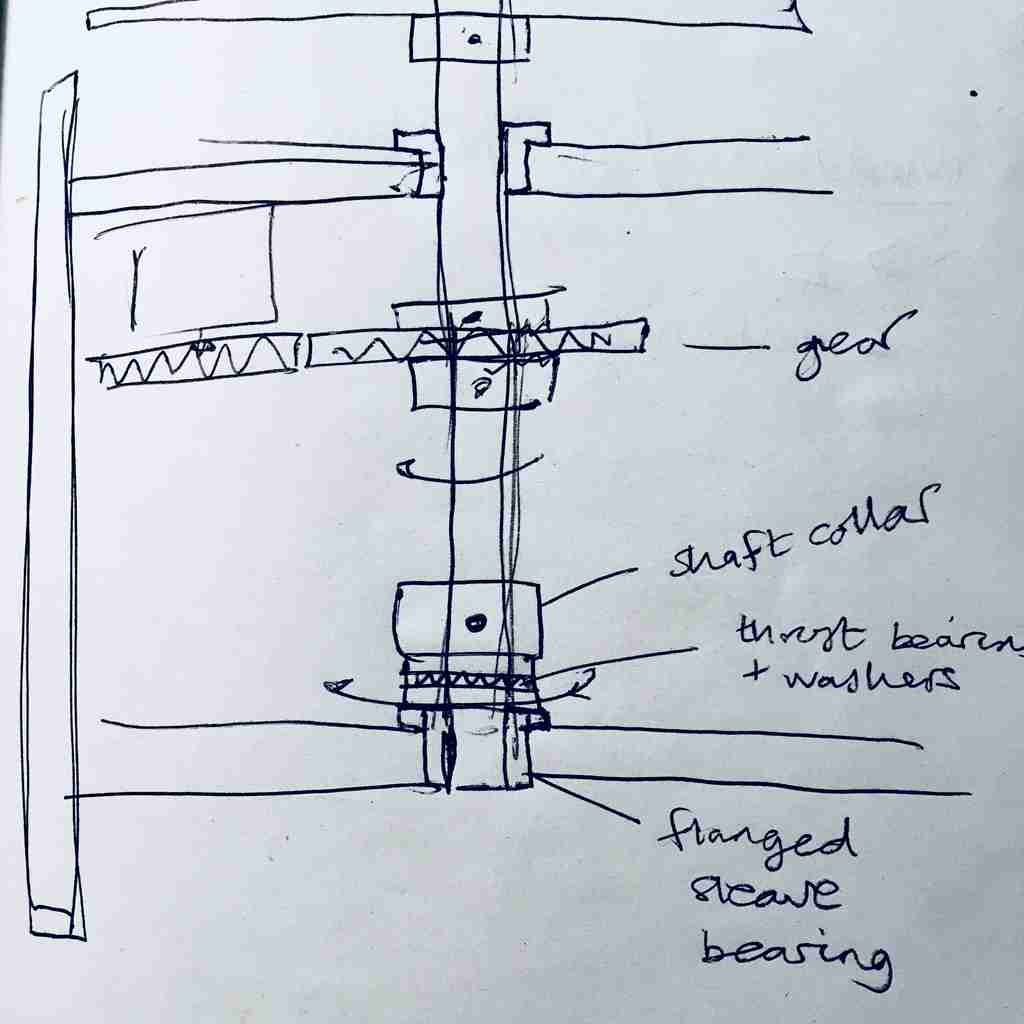
My basic idea was to support fix the shaft using shaft collars (relatively easy to find) and rotate the collar on a thrust bearing something like this. The first hand drawn design included a gear box to drive the generator, while the second CAD section shows my subsequent “direct drive” design.
 |
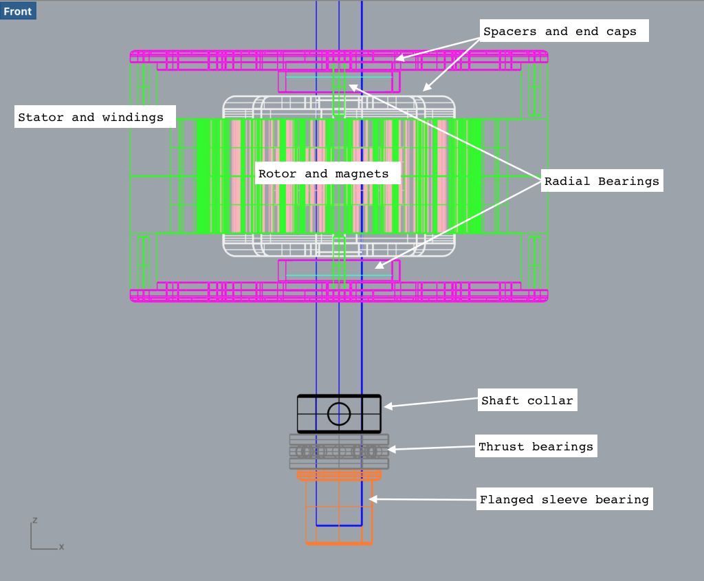 |
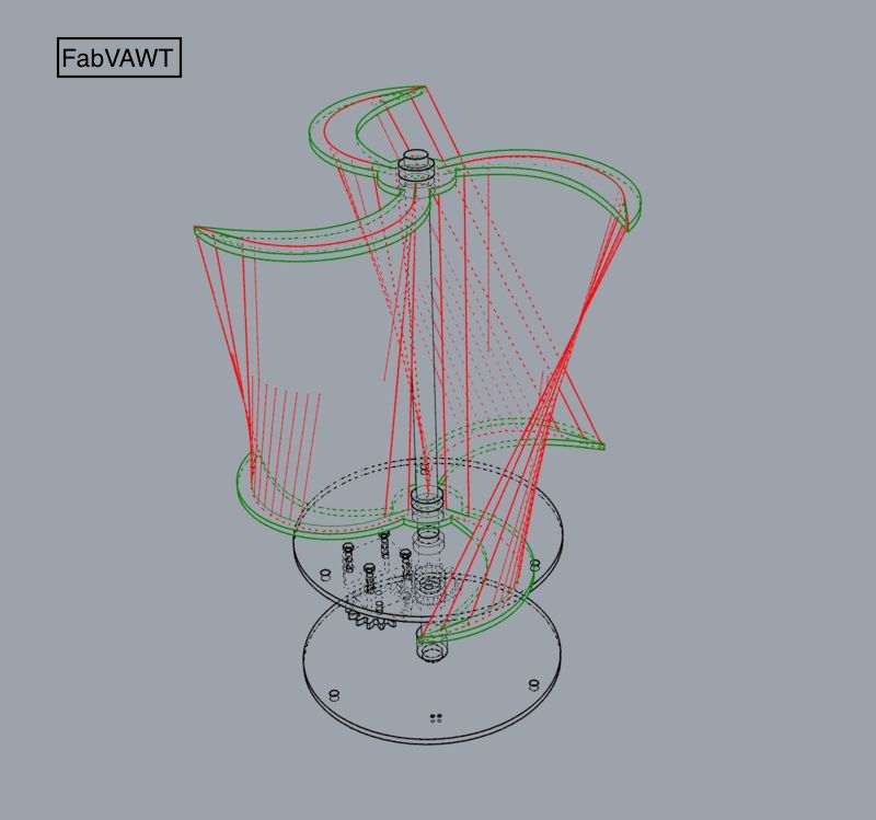
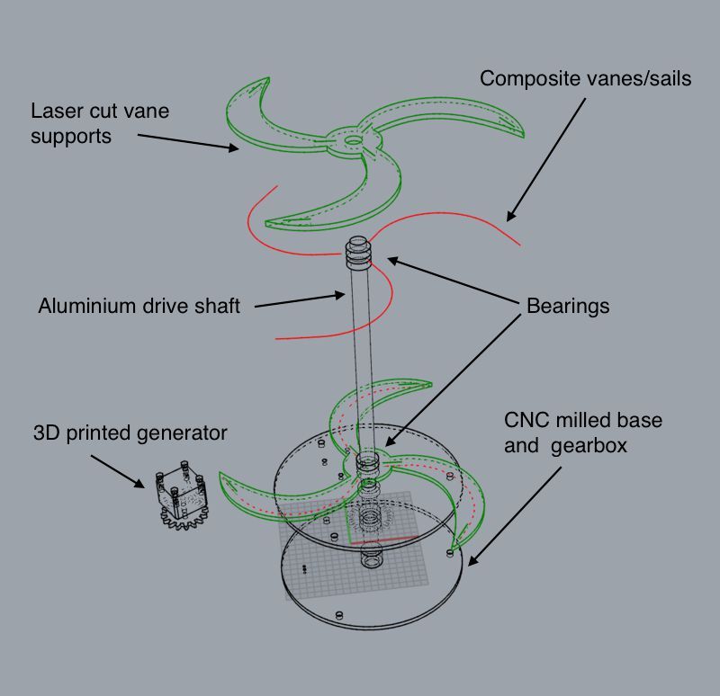
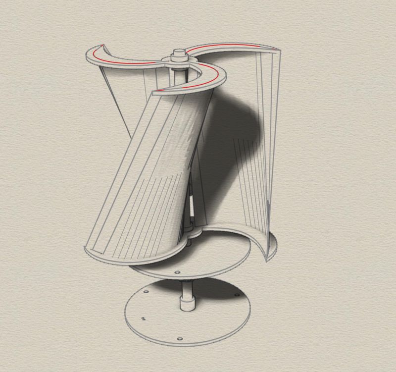
And finally, here is my final design made in Rhino CAD.