Final Project
Fab Train
Interactive STEM Train Kit with Modular Wooden Rails, Smart Station, Embedded Control and Real-Time Dashboard
1. Final Project Checklist
- ✅ Created a complete final project page
- ✅ Documented what the project does
- ✅ Explained who has done similar work and the project context
- ✅ Documented what was designed and fabricated
- ✅ Listed the materials and components used
- ✅ Included the Bill of Materials summary
- ✅ Explained where the components came from
- ✅ Documented what parts and systems were made
- ✅ Documented the fabrication, packaging and integration processes
- ✅ Explained what worked, what did not, and what questions remain
- ✅ Included final project slide and video links
- ✅ Linked to Week 20 final project requirements
- ✅ Included editable source files and fabrication-ready files in the downloadable archive
- ✅ Included license and acknowledgements
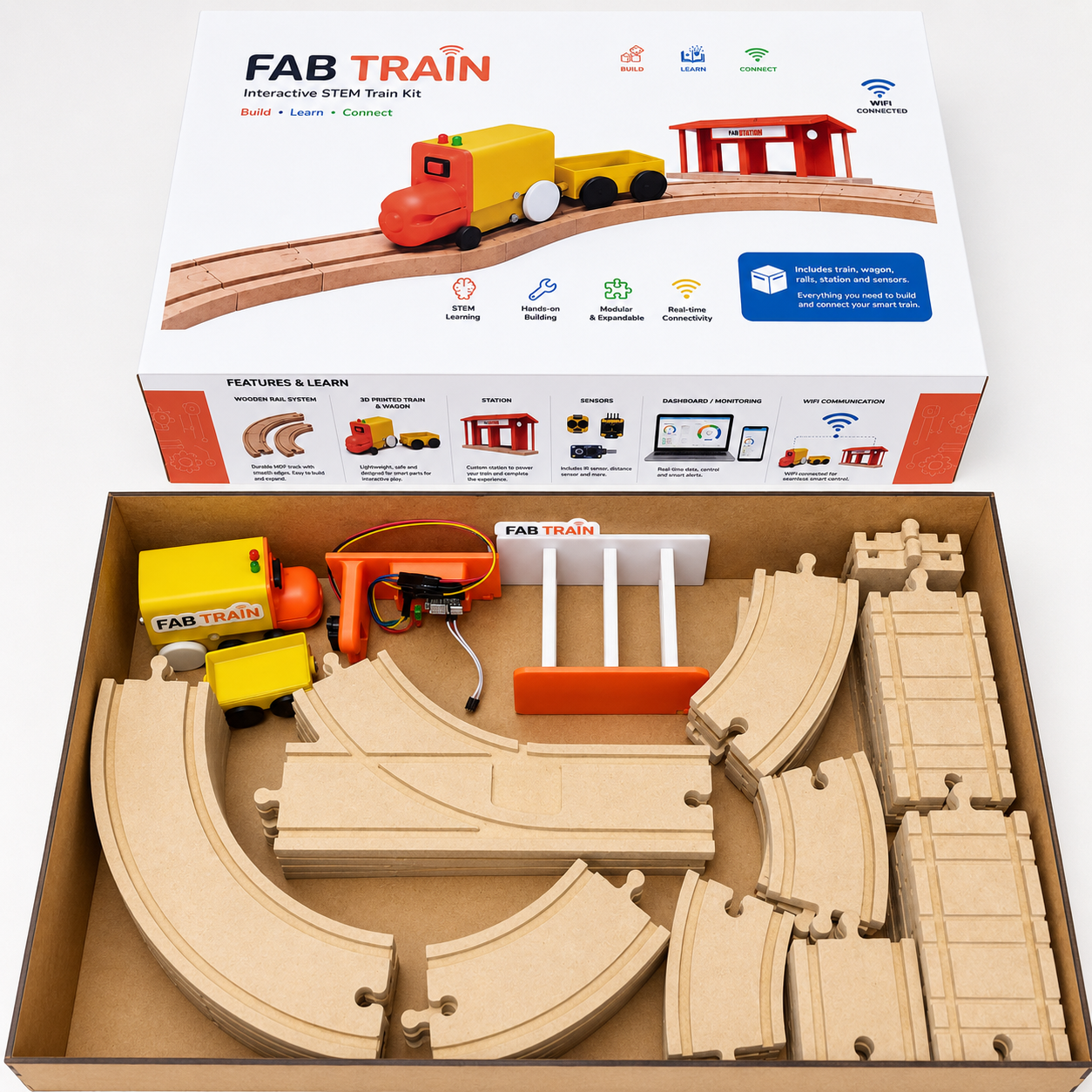
2. Project Overview
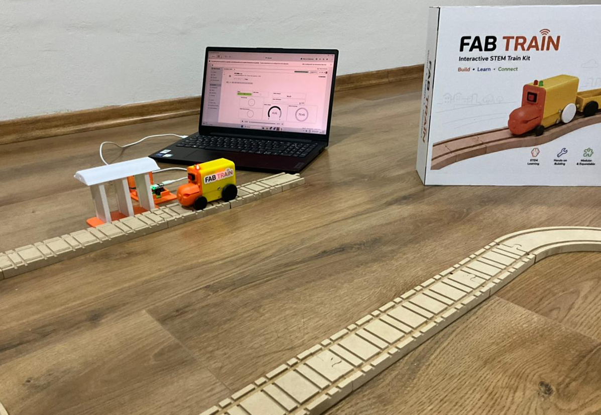
Fab Train is an interactive STEM train kit that combines digital fabrication, electronics, embedded programming, wireless communication and interface design. The system includes modular wooden rails, a 3D printed train, a wagon, a smart station, custom electronics, WiFi communication and a real-time dashboard made with Blynk.
The objective of the project is to create a demonstrative and educational kit where the user can assemble a rail circuit, place the train and the station, start the system from a dashboard, and observe how the train interacts with the station. When the station detects the train using a Sharp distance sensor, it sends a stop command. The train stops and waits until the user presses the Blynk button again to continue.
Fab Train was designed as a possible STEM learning platform. It can be used to explain modular design, digital fabrication, electronics, sensors, actuators, dashboards, IoT communication and system integration in a hands-on way.
3. What Does It Do?
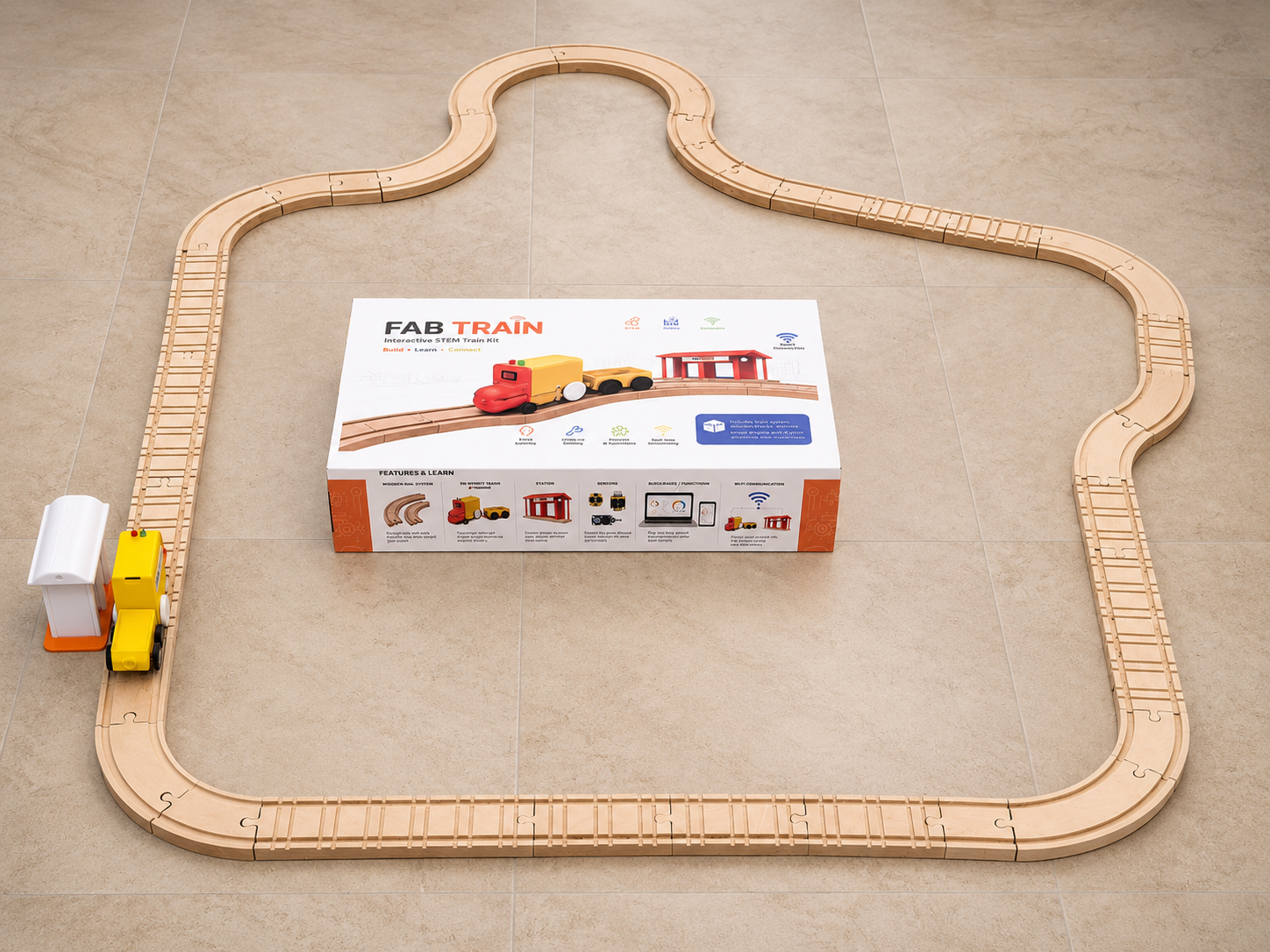
Fab Train works as a modular train kit. The user can build a rail circuit using CNC-machined MDF rail pieces, place the train and wagon on the track, connect the smart station, and control the system from a Blynk dashboard.
The train contains a XIAO ESP32-C6, a motor driver, a DC motor, LEDs, a battery voltage reading circuit and a battery supply. The station contains another XIAO ESP32-C6, a Sharp distance sensor and LEDs. Both systems communicate through WiFi using the Blynk platform.
- The user presses a button in Blynk to start the train.
- The train moves along the modular wooden rail circuit.
- The smart station measures the distance using the Sharp sensor.
- When the train is detected in the station range, the station sends a stop command.
- The train stops and remains stopped until the user presses the Blynk button again.
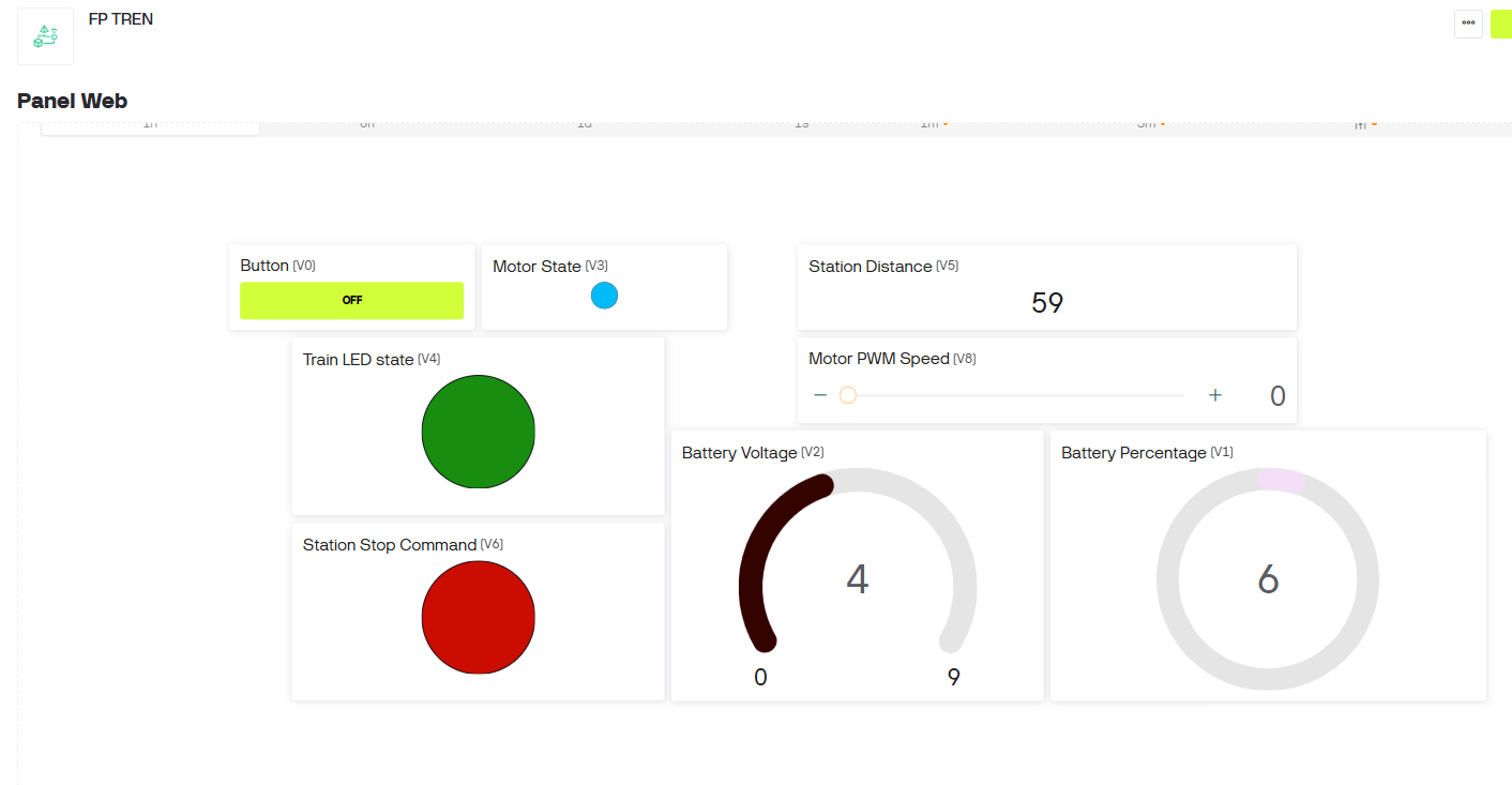
- The dashboard shows motor state, train LED state, station distance, stop command, battery voltage, battery percentage and PWM speed.
4. Final Slide and Video
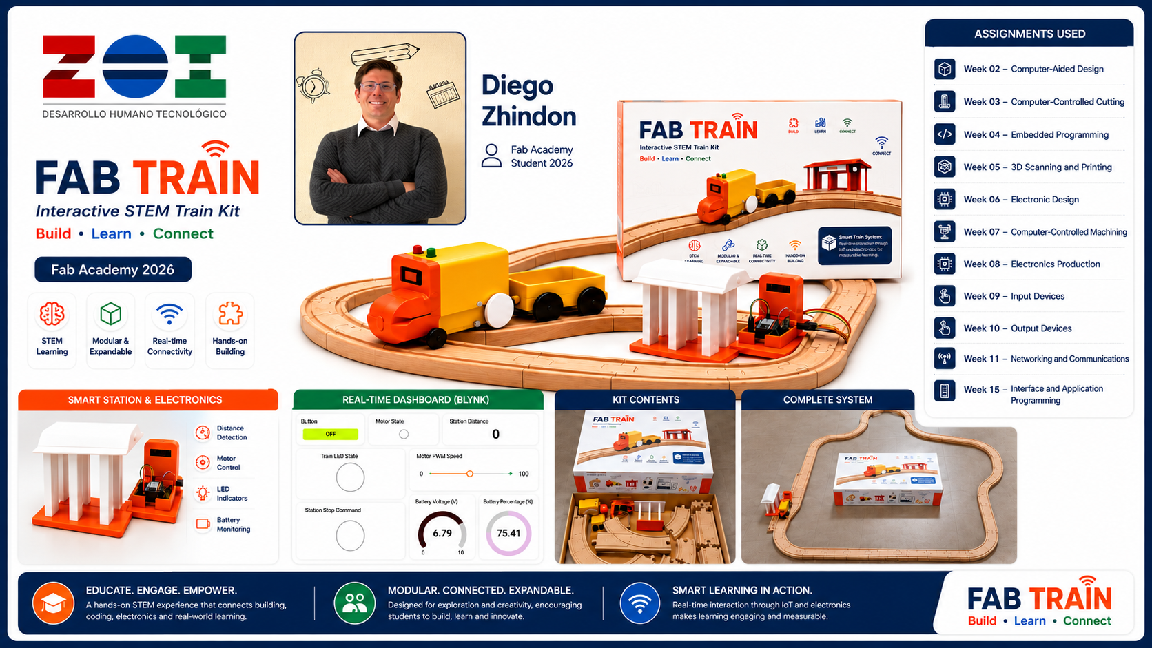
The final project slide and video are included as required for the final presentation. The slide summarizes the project, the student information, the Fab Lab, the assignments used, and the main system features. The video presents the final project concept, fabrication, assembly and operation.
presentation.png.
presentation.mp4.
Image source: The image presentation.png was generated
with an AI image generation tool.
Final Slide Generation Workflow
For the final project slide, I created a horizontal summary image with the required
Fab Academy presentation format. The slide was prepared at
1920 × 1080 px in a 16:9 aspect ratio, and it was exported as
presentation.png.
The slide was designed to communicate the complete Fab Train system in one image. It includes the project name, my name, Fab Academy 2026, ZOI Lab identity, the final packaging, train, wagon, station, rails, dashboard and the main assignments used to develop the project.
Prompt — Final project slide
Create a professional high-impact horizontal 16:9 final presentation slide for a Fab Academy 2026 final project called “FAB TRAIN”. The slide must be exactly 1920 × 1080 px. Use a clean white background with a premium educational product style. Show the complete interactive STEM train kit as the central focus: a yellow and orange 3D printed train with wagon on modular wooden rails, a smart station, a real-time IoT dashboard, and the final packaging box. Include the project title “FAB TRAIN”, subtitle “Interactive STEM Train Kit”, tagline “Build • Learn • Connect”, student name “Diego Zhindon”, Fab Academy 2026, and ZOI Lab logo. Add a section titled “Assignments Used” listing Week 02 Computer-Aided Design, Week 03 Computer-Controlled Cutting, Week 04 Embedded Programming, Week 05 3D Scanning and Printing, Week 06 Electronics Design, Week 07 Computer-Controlled Machining, Week 08 Electronics Production, Week 09 Input Devices, Week 10 Output Devices, Week 11 Networking and Communications, and Week 15 Interface and Application Programming. Add small feature icons for STEM learning, modular and expandable rails, real-time connectivity, hands-on building, smart station and electronics, and dashboard monitoring. The composition should look polished, modern, readable, visually balanced, high resolution, professional, and suitable for a Fab Academy final project presentation.
After generating the slide, I verified that the final image matched the required
horizontal format and used it as the final presentation.png file.
5. Who Has Done What Beforehand?
Educational train kits, wooden rail systems, STEM toys and IoT learning platforms already exist in different forms. Traditional wooden train toys are commonly used to teach assembly, spatial reasoning and creativity. Other STEM kits use sensors, motors and microcontrollers to teach programming and electronics.
Fab Train combines ideas from these areas, but adapts them to the Fab Academy workflow. The project is not only a purchased kit; it is a digitally fabricated system where the rails, train parts, station, electronics, dashboard and packaging were designed and developed as part of the final project process.
The difference is that Fab Train connects traditional hands-on play with digital fabrication and IoT monitoring. It becomes both a physical kit and a connected prototype that can be expanded for future STEM education activities.
6. What Did I Design?
The project required the design of several mechanical, electronic and visual elements. The final design was developed progressively through the weekly assignments.
- Modular MDF rail pieces with straight, curved and bifurcation sections.
- 3D printed train body.
- 3D printed wagon.
- 3D printed wheels and axles.
- 3D printed station structure.
- Custom PCB for the train controller.
- Custom PCB for the station controller.
- Blynk dashboard for monitoring and control.
- Packaging box and adhesive vinyl graphic design.
- Final presentation slide and project communication graphics.
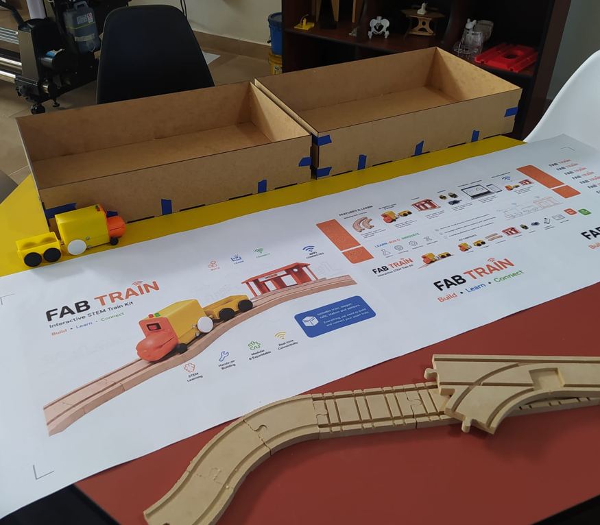
7. Rail System
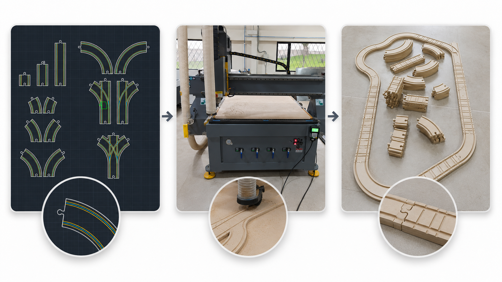
The rail system was designed in 2D using AutoCAD. The objective was to create a modular wooden rail set that could be assembled in different configurations. I designed straight rails in different lengths, curves at different angles, and bifurcation pieces for more flexible layouts.
The rails were fabricated using CNC machining on 12 mm MDF. The internal channels for the train wheels were machined with an end mill, and the external profile was cut through the complete material thickness. After machining, the rails were removed, cleaned and sanded to improve the final finish and fit.
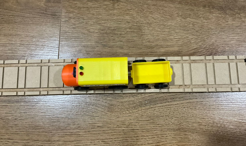
8. Train and Wagon
The train and wagon were designed in 3D and fabricated using 3D printing. The train body was designed to contain the main electronics, motor, wiring, LEDs and power system. The wagon was designed as an additional modular part that follows the train on the rail circuit.
Several prototypes and dimensional tests were necessary to improve the fit between the wheels, the rail channel and the train body. This process demonstrated the importance of iterative 3D printing for mechanical validation.
9. Electronics
Fab Train uses two XIAO ESP32-C6 boards. One controls the train and the other controls the station. The train PCB includes the microcontroller, motor control, LEDs, battery voltage reading and power regulation. The station PCB includes the microcontroller, Sharp distance sensor connection, LEDs and external 5 V power input.
The PCB design process was developed in EasyEDA. The boards were fabricated in FR4 using CNC milling and then soldered with through-hole and SMD components. During testing, continuity and voltage levels were checked to avoid connection problems and to protect the XIAO inputs.
- Train controller: XIAO ESP32-C6, L9110S motor driver, DC motor, LEDs, voltage divider and battery monitoring.
- Station controller: XIAO ESP32-C6, Sharp distance sensor, LEDs and external 5 V supply.
- Communication: WiFi through Blynk.
- Interface: Blynk dashboard with virtual pins for control and monitoring.
10. Inputs and Outputs
The main input device is the Sharp distance sensor in the station. It is used to detect when the train reaches the station. The train also reads the battery voltage using an analog input and a voltage divider, allowing the dashboard to show the battery condition.
The main output devices are the DC motor and the LEDs. The DC motor moves the train, while the LEDs provide visual feedback for the system states. These outputs are also represented in the Blynk dashboard.
| Subsystem | Input / Output | Function |
|---|---|---|
| Station | Sharp distance sensor | Detects train arrival at the station. |
| Train | Battery voltage reading | Monitors battery voltage and percentage. |
| Train | DC motor | Moves the train through the rail circuit. |
| Train and station | LEDs | Show visual status of the system. |
11. Networking and Dashboard
The train and station communicate with the Blynk dashboard through WiFi. The dashboard was created using Blynk widgets and virtual pins. It allows the user to start or resume the train, control the PWM motor speed, and monitor the main variables of the system.
The dashboard includes widgets for button control, motor state, train LED state, station stop command, station distance, motor PWM speed, battery voltage and battery percentage.
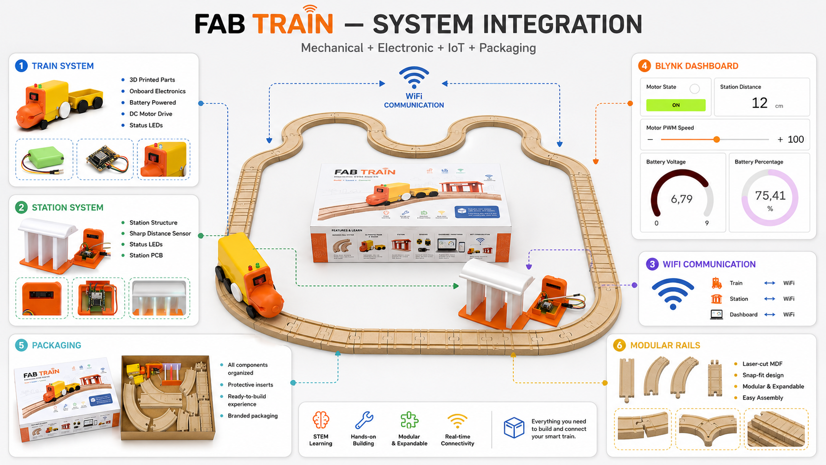
12. System Integration
System integration was the most important part of the final project because Fab Train had to work as one complete system. The mechanical rail system, the 3D printed train, the station, the custom electronics, the embedded code, the dashboard and the packaging all had to be coordinated.
The final integrated behavior is a loop. The user starts the train from Blynk. The train moves through the rail circuit. When it reaches the station, the Sharp sensor detects the train and sends a stop command. The train stops, and when the user presses the button again, the train resumes movement and the system is ready for the next cycle.
A latch logic was added to the station detection. This was necessary because the train can pass quickly through the sensor zone. With the latch, the station stores the detection event and keeps the stop command active until the user starts the train again.
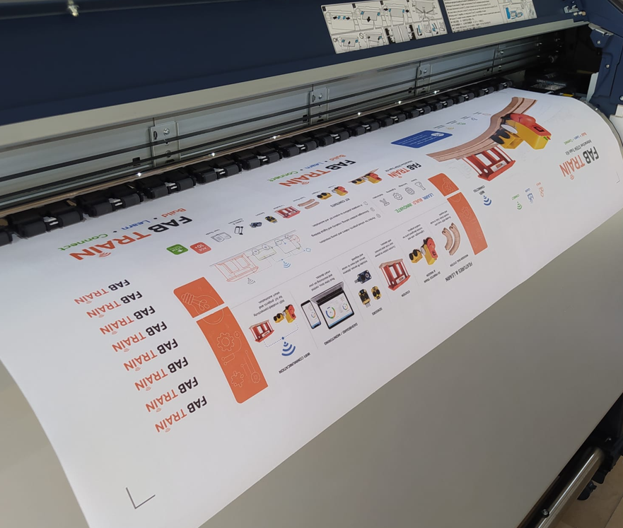
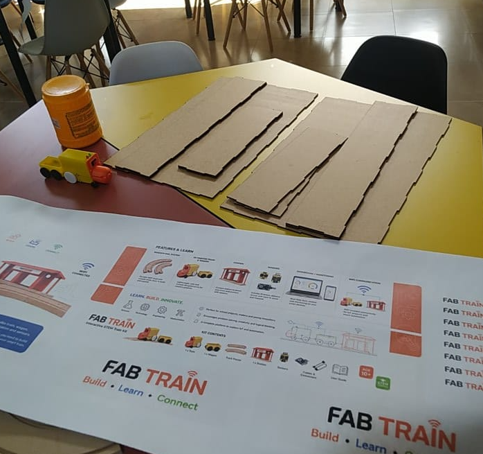
13. Packaging Design and Fabrication Process
The packaging was designed to present Fab Train as a complete educational kit. The box stores the train, wagon, station, rails and accessories. The final box dimensions are approximately 50 cm × 31 cm × 10 cm.
The packaging development combined graphic design, laser cutting, adhesive
assembly and vinyl application. The graphic artwork was created in
Adobe Illustrator, while the box structure was prepared as
editable DWG and fabrication-ready DXF files.
The final visual design was exported and printed on adhesive vinyl.
The packaging structure was divided into two main laser-cut parts: the external box and the internal or complementary box component. After laser cutting the pieces, the walls and joints were assembled using adhesive. The printed vinyl was then cut with a plotter according to the dimensions of the external faces and carefully applied to the outside walls of the packaging.
| Step | Process | Tool / material | Result |
|---|---|---|---|
| 1 | Graphic and structural design | Adobe Illustrator and 2D CAD files | Packaging artwork, dimensions, external graphics and box cutting geometry were prepared. |
| 2 | Vinyl printing | Printed adhesive vinyl | The final graphic design was printed at the dimensions required for the external walls of the box. |
| 3 | Laser cutting | Laser cutter and MDF sheets | The two main packaging parts and their walls were cut from the digital fabrication files. |
| 4 | Box assembly | Adhesive / glue | The laser-cut walls and structural parts were joined to form the external packaging. |
| 5 | Plotter cutting and vinyl application | Cutting plotter and adhesive vinyl | The printed sticker was cut to size and applied to the external box walls, aligning the design with the packaging dimensions. |
14. Materials and Bill of Materials
The project uses digital fabrication materials, electronic components, mechanical parts and packaging materials. The detailed BOM and cost analysis are documented in Week 18.
| Category | Main items | Use |
|---|---|---|
| Fabrication materials | MDF 3 mm, MDF 12 mm, PLA filament and adhesive vinyl | Rails, train, station and packaging. |
| Electronics | XIAO ESP32-C6, FR4 boards, resistors, capacitors, regulator, pin headers | Train and station control boards. |
| Motion | DC motor with gearbox and L9110S motor driver | Train movement. |
| Sensing | Sharp distance sensor and battery voltage divider | Station detection and battery monitoring. |
| Assembly | Magnets, M3 screws, nuts and jumpers | Mechanical and electronic assembly. |
The estimated total cost of the final prototype was approximately 124.95 USD, based on the detailed BOM documented in Week 18.
15. Editable Source Files and Fabrication Files
The complete Fab Train file package includes both the original editable source files and the fabrication-ready export files. This allows the project to be studied, modified and fabricated instead of providing only final export formats.
Editable files preserve the original design information and can be modified using the corresponding software. Fabrication files are the exported formats used directly for 3D printing, CNC machining, laser cutting, PCB production and microcontroller programming.
| File group | Editable source files | Fabrication / production files | Purpose |
|---|---|---|---|
| 3D mechanical design | .ipt |
.stl |
Editable Autodesk Inventor models and 3D printing files for the train, wagon, wheels, axles and station components. |
| Rail system | .dwg |
.dxf |
Editable 2D rail drawings and CNC machining files for the modular MDF track pieces. |
| Packaging structure | .dwg |
.dxf |
Editable box geometry and laser cutting files for the two packaging components. |
| Packaging graphic design | .ai |
Print-ready artwork included in the archive | Editable Adobe Illustrator artwork used for adhesive vinyl printing and plotter cutting. |
| Train and station PCBs | .json |
Gerber files | Editable EasyEDA board projects and production files for PCB fabrication. |
| Embedded programming | .ino |
.ino |
Editable Arduino programs for the train and station XIAO ESP32-C6 controllers. |
| Final presentation resources | Source resources included where applicable | presentation.png and presentation.mp4 |
Final communication materials used for the Fab Academy presentation. |
The archive therefore contains the files required to modify the project as well as the files required to reproduce its mechanical parts, rails, packaging, electronic boards and embedded programs.
16. What Worked and What Did Not?
| Aspect | Result | Comment |
|---|---|---|
| Rail system | Worked | The MDF rails were successfully machined and assembled. |
| Train movement | Worked | The train moved on the wooden rails with PWM motor control. |
| Train and wagon 3D prints | Worked | The 3D printed parts were adjusted to fit the rail system. |
| Station detection | Worked after calibration | The Sharp sensor detected the train in the station range. |
| Stop command | Worked after logic adjustment | A latch was needed so the train could stop even if it passed quickly. |
| Blynk dashboard | Worked | The dashboard displayed train and station data in real time. |
| Battery | Worked with limitations | The 9 V battery worked, but a rechargeable battery with better current capacity would improve reliability. |
| Packaging | Worked | The box stores and presents the project as a complete kit. |
17. Questions and Future Development
The final prototype works as a demonstrative educational system, but there are still opportunities for improvement and future development.
- Replace the 9 V battery with a rechargeable battery system.
- Add an integrated charging method for the train.
- Improve the power system to reduce voltage drops when the motor starts.
- Improve the station power system with a more permanent regulated supply.
- Use direct communication such as ESP-NOW in a future version for faster train-station response.
- Add more sensors or stations to create more complex STEM activities.
- Develop classroom activities or maker workshop guides based on the kit.
- Improve the mechanical finish of the rails with sealing or surface treatment.
18. License and Dissemination
Fab Train is documented openly through the Fab Academy website and GitLab. The intention is to share the design, fabrication process, code and project development so that students, makers and educators can study it, reproduce it or adapt it for educational purposes.
For the documentation, I use a Creative Commons Attribution-NonCommercial approach. The project can be shared and adapted with attribution, but it is not intended for direct commercial use without permission.
19. Acknowledgements
This project was developed as part of Fab Academy 2026 at ZOI Lab. I acknowledge the support of the local instructors, classmates and Fab Lab community during the design, fabrication, electronics and integration process.
I also acknowledge the use of Arduino IDE, Blynk, EasyEDA, AutoCAD, Inventor, CNC machining workflows, 3D printing tools and the open documentation culture of Fab Academy.
20. Final Reflection
- Fab Train helped me understand that a final project is not only a single object, but a complete system where mechanical design, electronics, programming, communication, interface design and packaging must work together.
- The project showed me the importance of dividing a complex system into subsystems. The rails, train, wagon, station, electronics, dashboard and packaging were developed separately, but the final value came from integrating them correctly.
- CNC machining was essential for the rail system because it allowed me to create repeatable wooden parts with functional grooves and modular connections.
- 3D printing was important for rapid iteration. I could test train parts, correct dimensions and improve how the train interacted with the rails.
- Electronics design and production helped me move from loose wiring to a more organized and reliable system.
- The Blynk dashboard made the project easier to understand because it transformed hidden electronic states into visible information.
- One of the most important technical lessons was that integration requires real testing. Some problems only appeared when the train, sensor, dashboard and power system were working together.
- Packaging changed the perception of the project. Once all parts were organized in a designed box, Fab Train became closer to a finished educational kit.
- Fab Academy helped me understand digital fabrication as a complete process: imagining, designing, fabricating, measuring, programming, testing, documenting and improving.
- Overall, Fab Train represents my synthesis of Fab Academy: a digitally fabricated, electronically controlled, connected and documented system that can continue evolving as an educational STEM platform.