
Week 05
3D Scanning and Printing
Additive Manufacturing, Process Comparison, and 3D Scanning
1. Checklist
- ✅ Documented the group assignment link
- ✅ Designed a printable object that is not easily made subtractively
- ✅ Prepared and printed the same object with different technologies and materials
- ✅ Compared print parameters such as layer height, infill, speed, and detail
- ✅ Evaluated printer limitations: overhangs, bridges, supports, and tolerances
- ✅ Included a short video of the printing process and final result
- ✅ Scanned a real object in 3D
- ✅ Explained scanning technology, workflow, limitations, and scan quality
- ✅ Included screenshots, process images, and downloadable STL files
- ✅ Reflected on the group and individual assignment
2. Group Assignment
For the group assignment, the lab tested the design rules of the available 3D printers. This included observing the behavior of the machines with different geometries, supports, bridges, overhangs, and dimensional conditions in order to understand their practical limitations and capabilities.
The group work was important because it provided a reference for the individual assignment. By understanding how each printer behaves with unsupported angles, bridges, tolerances, and support material, I could make better decisions when preparing my own 3D printed object.
3. Individual Assignment
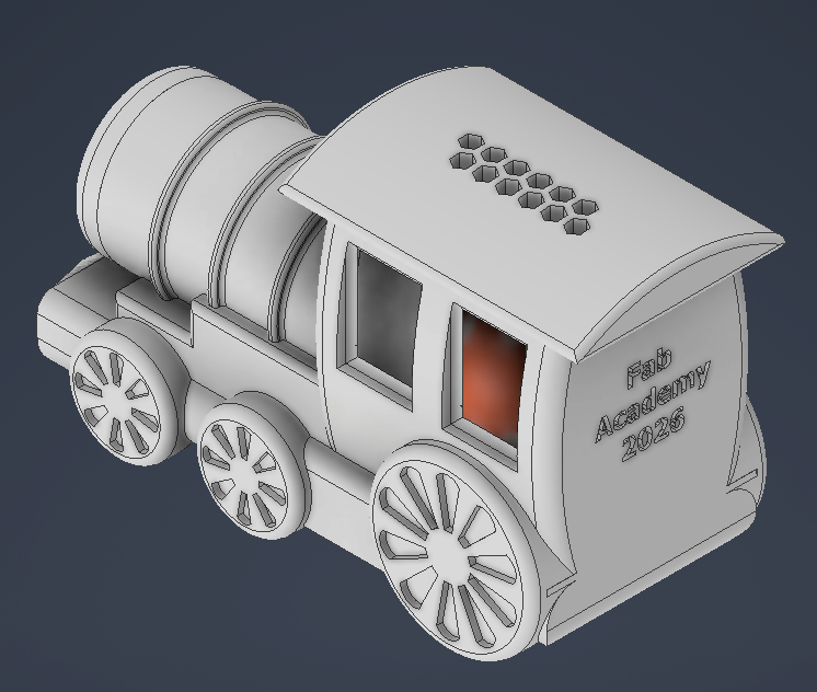
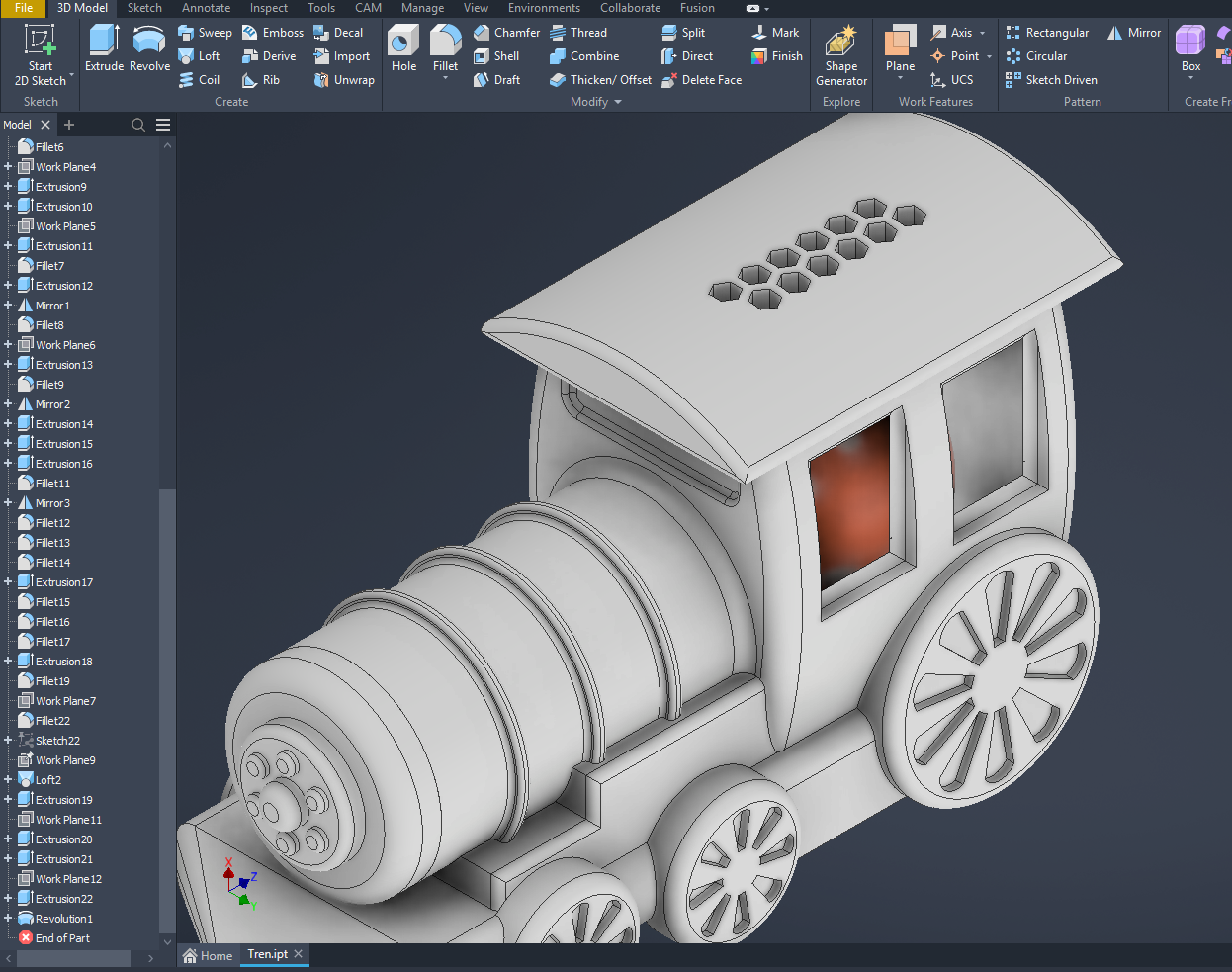
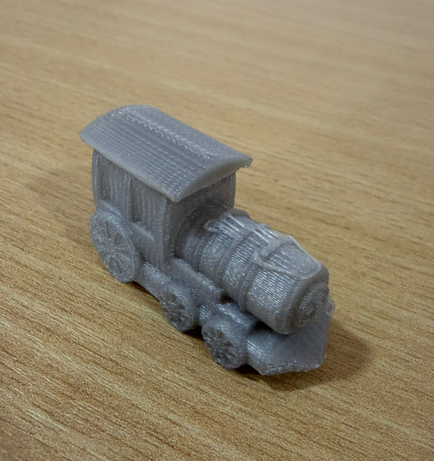
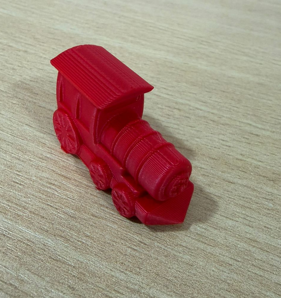
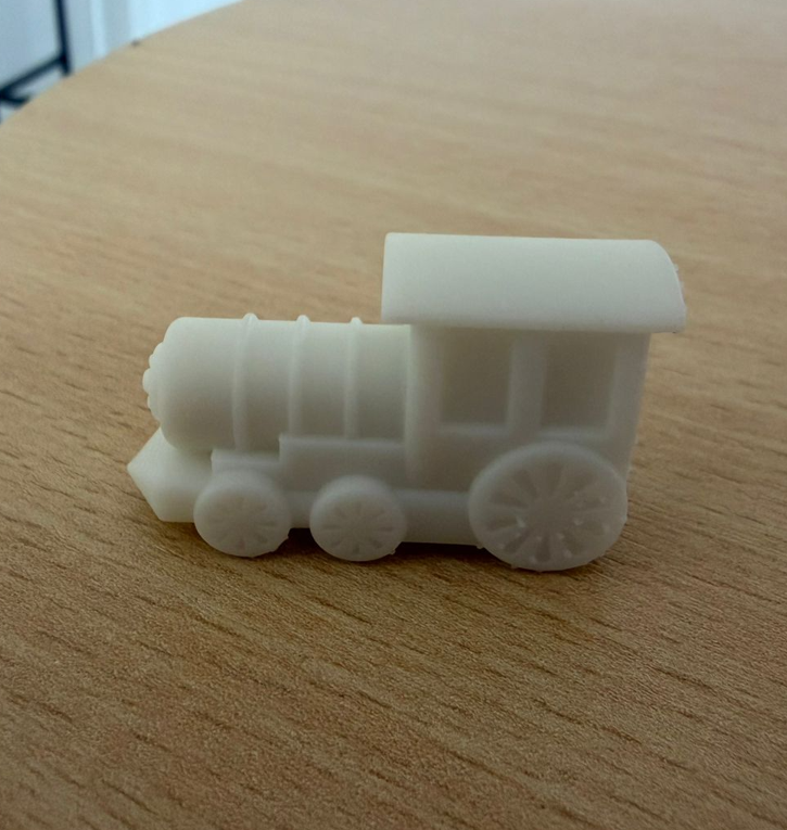
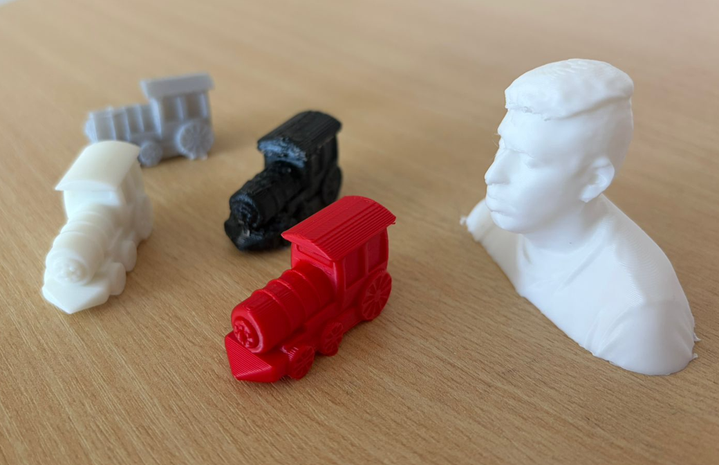
For the individual assignment, I designed a small train in Autodesk Inventor and printed it using different additive manufacturing workflows. The same geometry was tested in FDM and resin printing to compare material behavior, print time, weight, surface finish, and level of detail. This object is suitable for 3D printing because it contains rounded shapes, small features, and supports-based geometries that would not be as direct to produce subtractively at this small scale.
3.1 Why this object is suitable for 3D printing
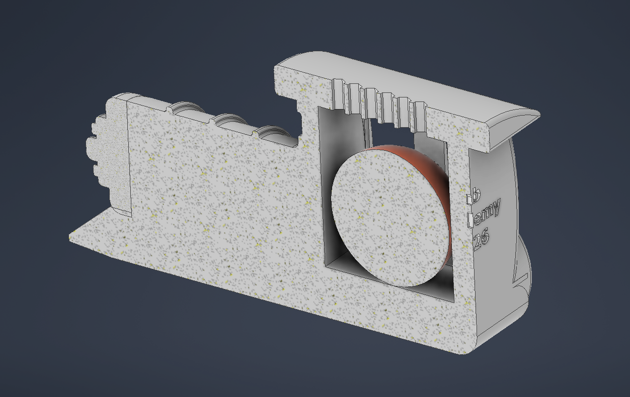
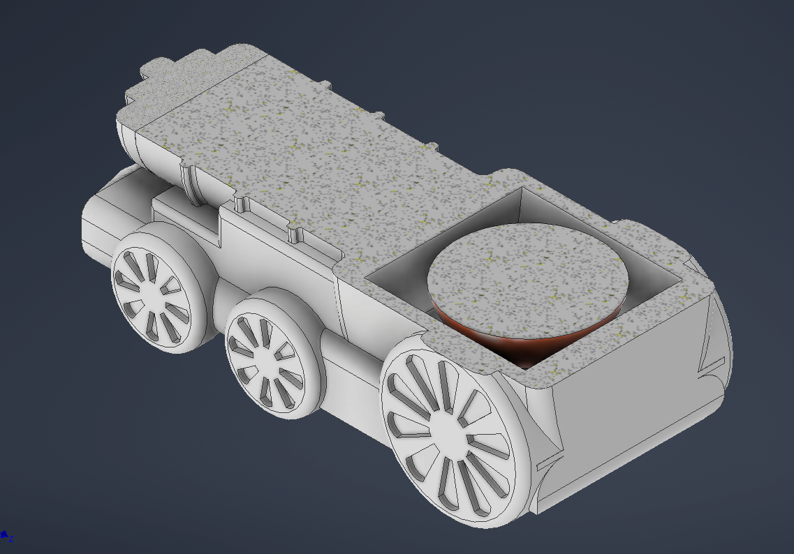
One of the requirements of this assignment is to design an object that cannot be easily made using a subtractive manufacturing process. In this case, the train model includes an internal spherical feature and enclosed internal geometry. This makes the part much more appropriate for additive manufacturing.
If this object were produced with CNC machining, the cutting tool would need physical access to every internal surface. Even with a multi-axis CNC machine, the cutter would not be able to enter and form the internal spherical structure without cutting the external body or dividing the model into several pieces. This is because subtractive tools remove material from the outside and require tool clearance, while 3D printing builds the part layer by layer and can create internal volumes during the fabrication process.
To verify this, I inspected the model using section views in Autodesk Inventor. The XY and XZ cuts show the internal structure of the train and confirm why additive manufacturing is a better process for this geometry.
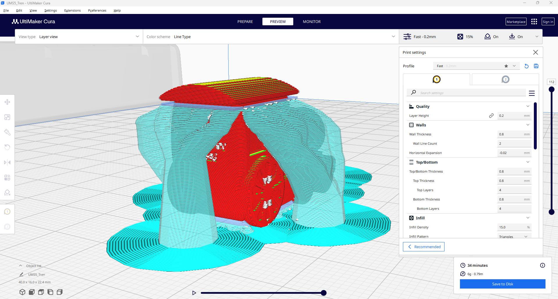
4. 3D Model Preparation
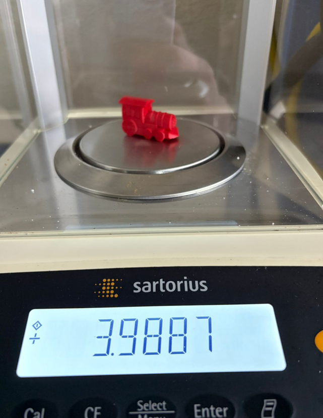
The train model was created in Autodesk Inventor and then exported as an STL file. The dimensions were adjusted to approximately 4 cm in length, keeping the rest of the geometry proportional to the original design. This scale made the comparison between printers, materials, and print settings more practical.
5. 3D Printing Process
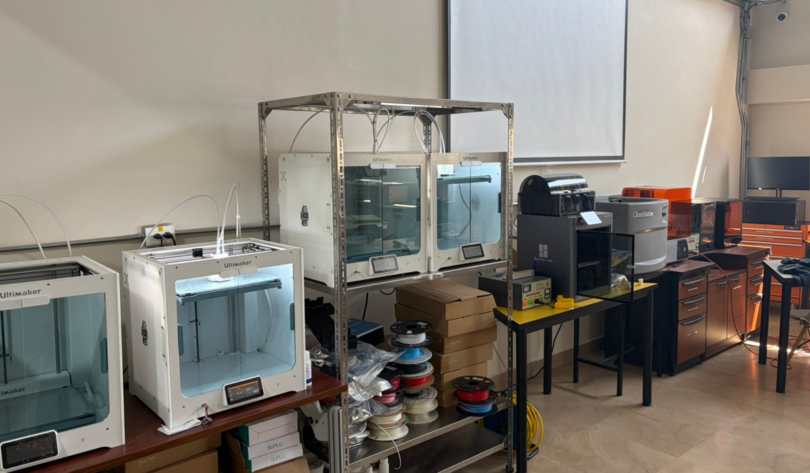
The same train model was printed in four different conditions: two prints on the Ultimaker S5, one print on the Bambu Lab X1E, and one print on the Formlabs 4 resin printer. This allowed a direct comparison between material type, layer height, infill, speed, and final quality.
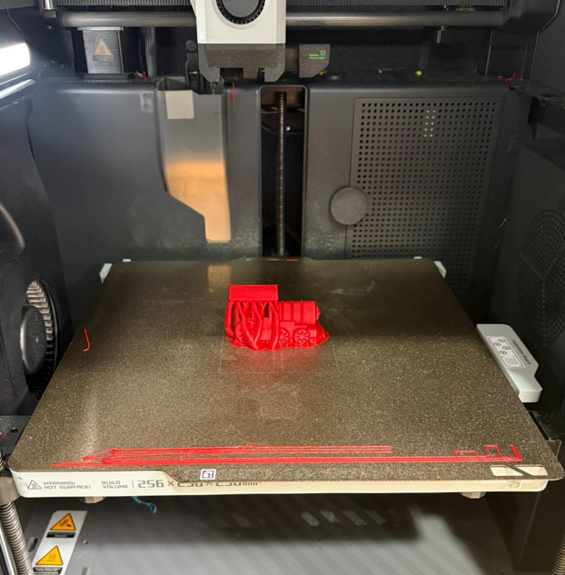
5.1 Ultimaker S5 — PLA
- Printer: Ultimaker S5
- Material: PLA
- Layer height: 0.2 mm
- Infill: 15%
- Supports: Tree supports
- Scale: train length approx. 4 cm
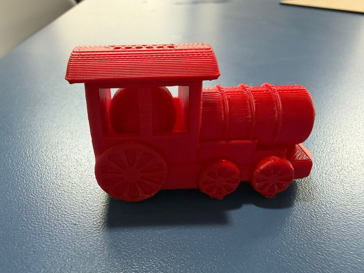
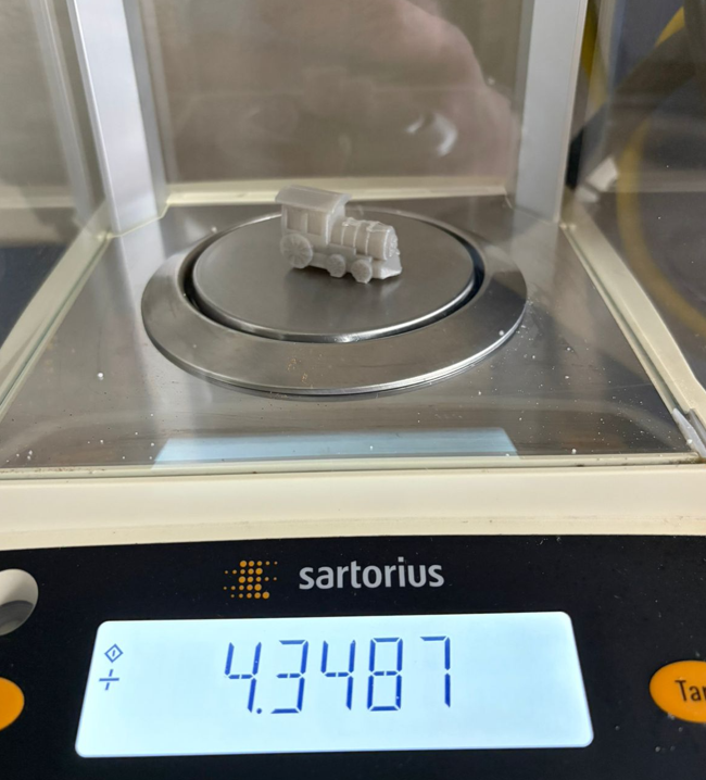
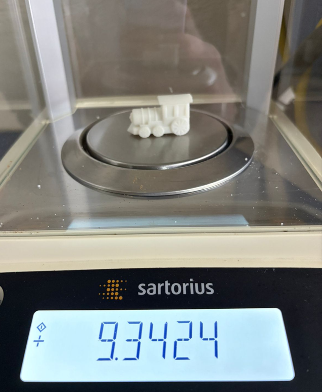
This first print was used as the lightweight FDM reference. With 15% infill and 0.2 mm layer height, the print maintained a good balance between material use, print time, and visible detail.
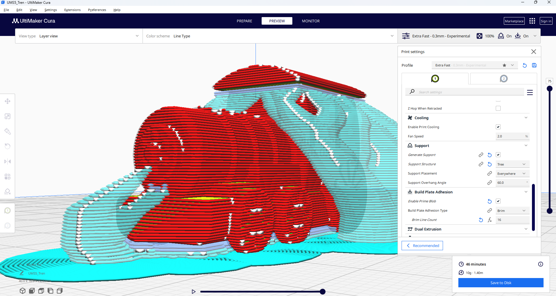
5.2 Ultimaker S5 — ABS
- Printer: Ultimaker S5
- Material: ABS
- Layer height: 0.3 mm
- Infill: 100%
- Supports: Tree supports
- Scale: same dimensions as the first print
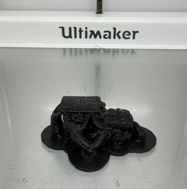
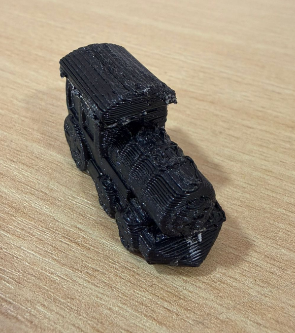
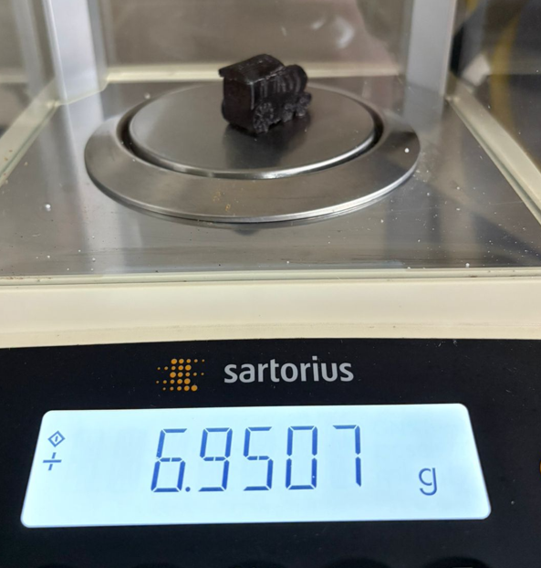
In this second print, the objective was to compare a denser and heavier part. With 100% infill, the model becomes solid and more resistant, while the 0.3 mm layer height reduces visible resolution compared to the finer settings.
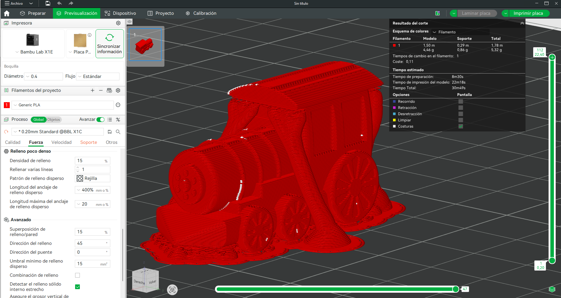
5.3 Bambu Lab X1E — PLA
- Printer: Bambu Lab X1E
- Material: PLA
- Layer height: 0.2 mm
- Infill: 15%
- Supports: Tree supports
- Scale: same train dimensions
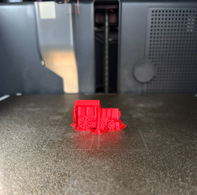
This print kept settings similar to the first Ultimaker PLA test, allowing a cleaner comparison focused on machine behavior and print speed. The Bambu system stands out for faster execution while preserving a good overall print quality.
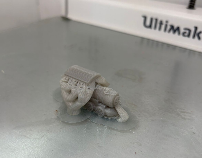
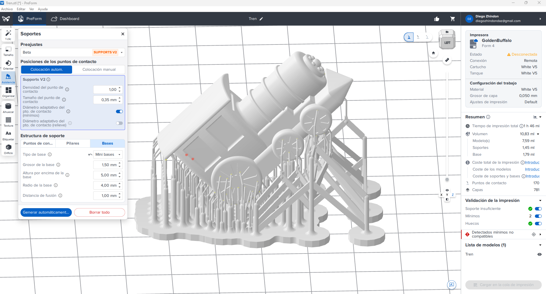
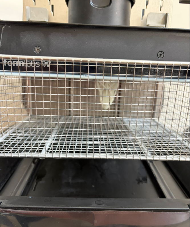
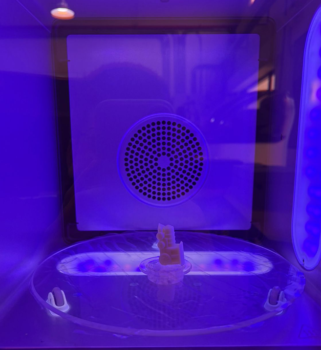
5.4 Formlabs 4 — White Resin
- Printer: Formlabs 4
- Material: White resin
- Layer height: 0.05 mm
- Part type: Solid
- Supports: Reduced support size with mini bases
- Post-processing: Wash 10 min + Cure 5 min
The resin print was used to evaluate fine detail and surface quality. Compared to FDM, this process offers much higher precision in small features and a cleaner surface finish, although it requires washing and curing steps after printing.
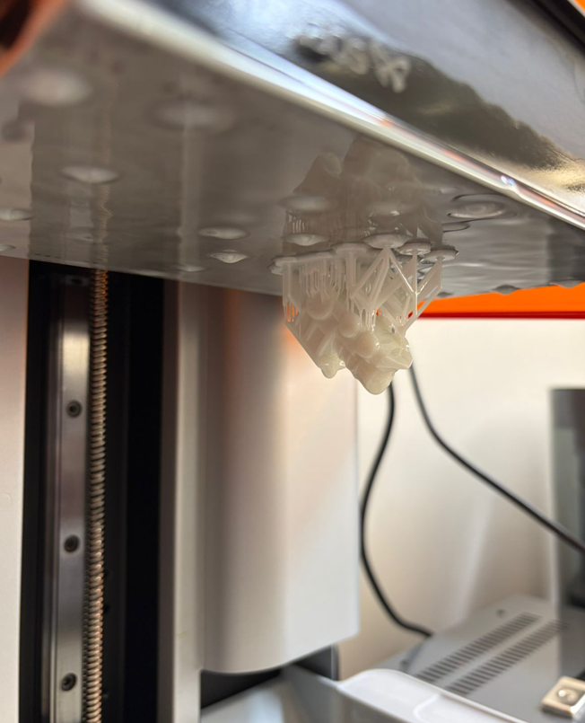
5.5 Printing video and final result
The following video shows part of the 3D printing process and the final printed result. This evidence helps connect the digital model, the slicing configuration, and the physical fabrication result.
6. Printing Comparison
| Machine / Material | Main settings | Quick observation |
|---|---|---|
| Ultimaker S5 / PLA | 0.2 mm, 15% infill, tree supports | Lighter part, balanced print quality, practical for fast prototyping. |
| Ultimaker S5 / ABS | 0.3 mm, 100% infill, tree supports | Heavier and denser part, lower visible resolution due to thicker layers. |
| Bambu Lab X1E / PLA | 0.2 mm, 15% infill, tree supports | Good quality with faster printing behavior. |
| Formlabs 4 / Resin | 0.05 mm, solid, reduced supports | Highest detail and best surface finish, but requires wash and cure. |
- 15% infill produces a lighter part and uses less material.
- 100% infill produces a heavier and more solid part.
- 0.2 mm layers provide a better balance between quality and time.
- 0.3 mm layers reduce detail but can simplify the print process.
- Bambu Lab improves speed noticeably.
- Resin printing gives the best small-detail definition.
7. Printer Limitations Evaluation
Based on the group assignment and my individual tests, I evaluated the main limitations of the available printers. This is important because a successful 3D print depends not only on the model, but also on knowing the limits of each machine and process.
| Feature | Bambu Lab X1E | Ultimaker S5 | Form 4 |
|---|---|---|---|
| Technology | FDM | FDM | SLA / resin printing |
| Nozzle / optical system | 0.4 mm nozzle | 0.4 mm nozzle | Resin light-based curing system |
| Resolution | Good | Good | Very high |
| Speed | Very high | Moderate | Moderate |
| Tolerance behavior | Excellent for FDM when calibrated correctly | Good and stable for general prints | High accuracy, but strongly dependent on orientation and support strategy |
| Bridge test | Up to 36 mm | Up to 36 mm | Not evaluated in the same way because resin printing requires support planning |
| Overhang test | Up to 70° with visible filament at the limit | Up to 60° cleanly, with visible filament at 70° | Requires support planning rather than unsupported overhang evaluation |
| Post-processing | Low | Low | High: wash and cure required |
For FDM printing, the most important limitations are overhangs, bridging, layer height, nozzle diameter, and tolerance. For my parts, a tolerance of approximately 0.2 mm is a good starting point for moving or mating parts. When inserting screws, pins, or components into printed holes, the hole usually needs to be designed approximately 0.2 mm larger to compensate for material expansion, extrusion behavior, and printer calibration.
Resin printing gives better detail and surface finish, but it requires support planning, washing, curing, and careful handling of liquid resin. Because of that, the best process depends on the goal: FDM is practical and fast for prototypes, while resin is better for small detailed parts.
8. Important Printing Rules
Before printing, it is important to consider several design and process rules that directly affect print quality, dimensional accuracy, material usage, and final reliability. The following guidelines summarize the most relevant factors I considered during this assignment.
| Rule / Parameter | Why it matters | Typical consideration |
|---|---|---|
| Supports | Prevent collapse in overhangs and suspended regions | Use tree or standard supports depending on geometry |
| Model orientation | Affects surface finish, strength, and amount of supports | Rotate the part to reduce unsupported areas |
| Layer height | Controls print resolution and print time | 0.2 mm is balanced, 0.05 mm gives much finer detail |
| Infill percentage | Defines weight, rigidity, and material consumption | 15% for lightweight parts, 100% for solid parts |
| Printing temperature | Influences adhesion and material flow | Must match the selected material profile |
| Print speed | Higher speeds reduce time but can reduce quality | Fast for prototypes, lower for better detail |
| Tolerances | Important for assemblies and fitting parts | Leave enough clearance between moving or mating parts |
| Warping | Can deform the base of the print, especially in ABS | Use proper bed adhesion and thermal control |
| Bed adhesion | Prevents the model from lifting during printing | Use brim, raft, or correct bed settings if needed |
| Post-processing | Required especially in resin workflows | Wash and cure steps are necessary after resin printing |
Common Materials
| Material | Main advantage | Main limitation | Typical use |
|---|---|---|---|
| PLA | Easy to print and dimensionally stable | Lower heat resistance | Prototypes and general-purpose prints |
| ABS | More resistant and durable | More sensitive to warping | Stronger functional parts |
| TPU | Flexible material | More difficult to print accurately | Flexible components and soft parts |
| Resin | Very high detail and smooth finish | Needs post-processing and careful handling | Detailed models and high-quality small parts |
9. 3D Scanning
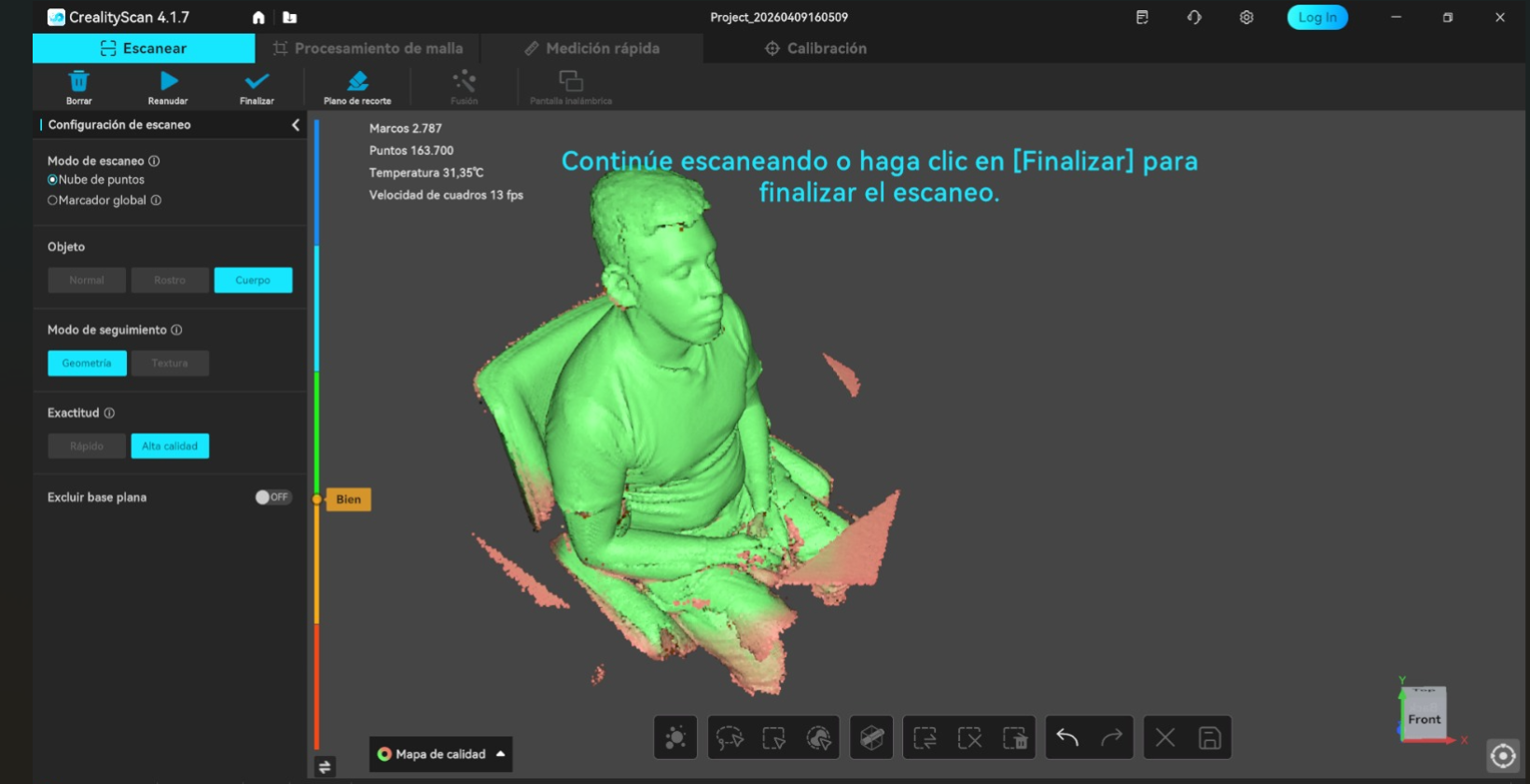
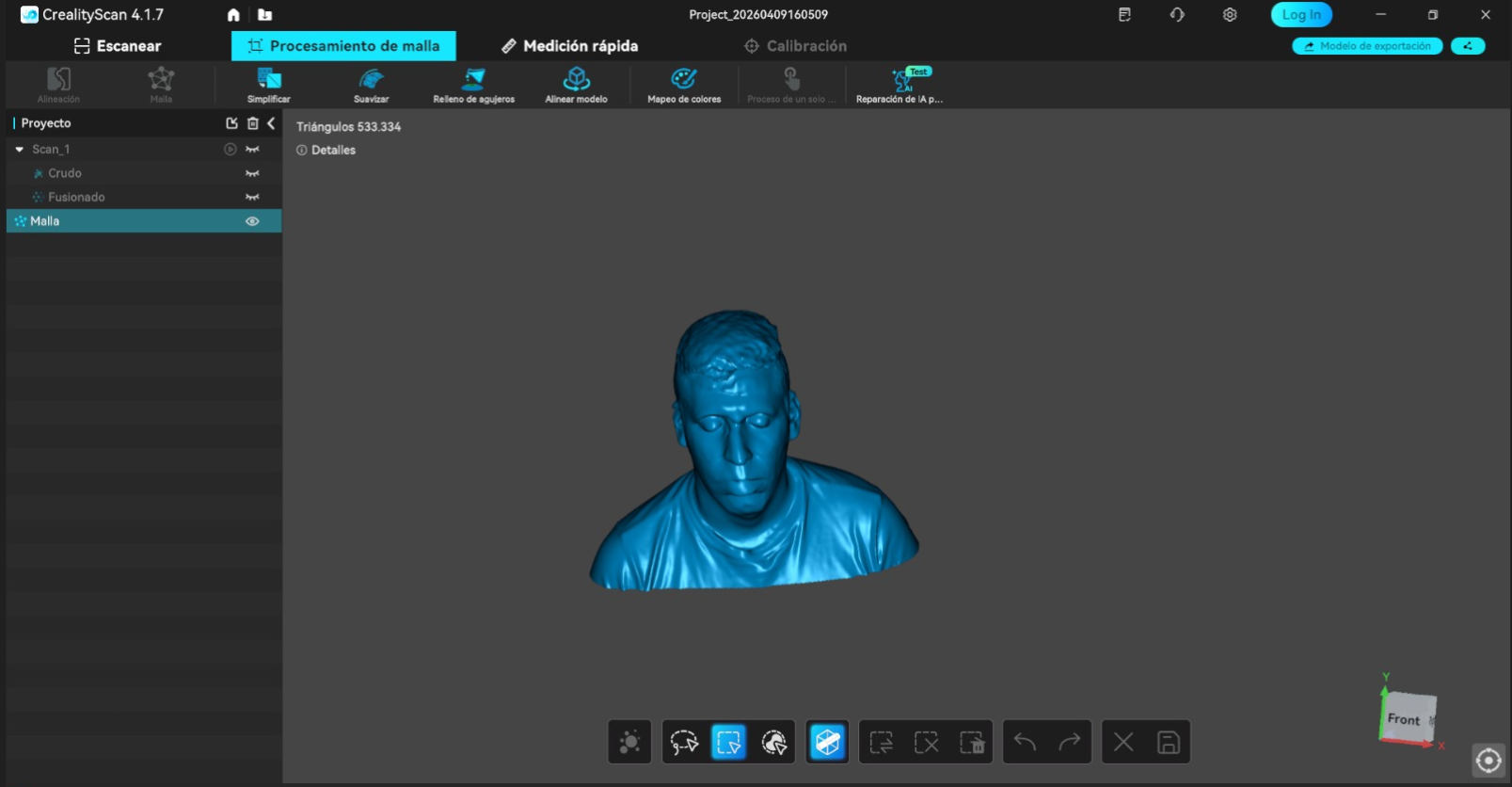
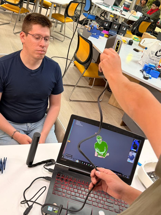
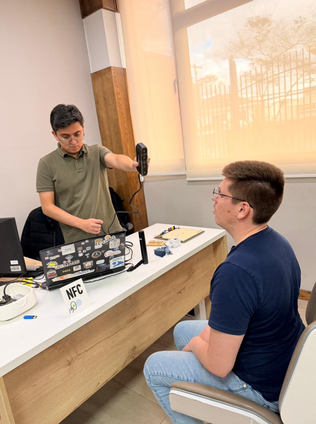
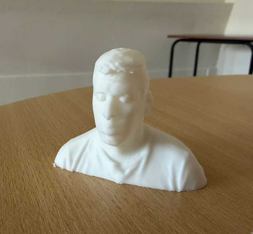
For the scanning process, I used the Creality CR-Scan Otter 3D Scanner Kit. The scanned subject was a bust of a person. To capture the bust properly, the subject remained seated on a rotating chair while the scanner operator moved around the subject and adjusted the capture process using the Creality software.
9.1 Scanning technology
The CR-Scan Otter is a handheld 3D scanner that uses structured light / infrared-based scanning and a multi-lens vision system to capture object geometry. This type of scanner projects or detects structured information from the surface and reconstructs the object as a digital point cloud and then as a mesh.
There are different 3D scanning technologies. Structured light scanners are common for objects, people, and medium-detail workflows. Laser scanners can be useful for high precision and industrial applications. Photogrammetry uses many photographs taken from different angles and reconstructs geometry using software. Contact scanning systems can be very accurate but are slower and less practical for organic shapes or people.
| Technology | Main idea | Advantages | Limitations |
|---|---|---|---|
| Structured light / infrared | Projects or detects light pattern information on the surface | Fast, good for people and objects, practical workflow | Sensitive to lighting, shiny surfaces, dark materials, and distance |
| Laser scanning | Uses laser lines or points to measure geometry | High precision, useful for industrial work | Can require markers and careful setup |
| Photogrammetry | Uses many photos from different angles | Low-cost and accessible | Depends strongly on texture, lighting, and image quality |
| Contact scanning | Physically touches the object to measure points | Very accurate for specific measurements | Slow and not ideal for people or fragile objects |
9.2 Scanning workflow
The workflow starts by preparing the physical object or person. If the subject is a person, it is very important that the person does not move, because movement can generate duplicated or distorted geometry. If the subject is an object, it is important to analyze its size, surface color, reflectivity, and position on the work area.
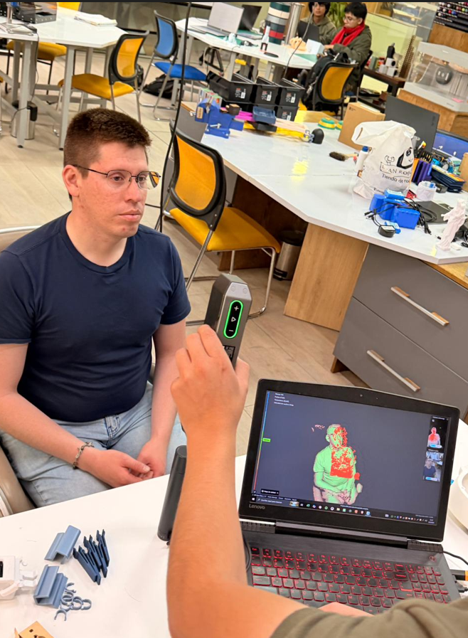
During scanning, the software gives visual feedback. In this case, the captured parts of the model are shown progressively while scanning. Red indicators generally appear when there are problems with distance, tracking, or lighting, while correctly captured zones are reconstructed as the scan advances.
For better results, the operator needs to move around the object slowly and maintain a stable distance. In some cases, a rotating table can be useful because it allows the object to rotate 360° while the scanner remains more stable. Areas with more detail may require slower movement or closer scanning.
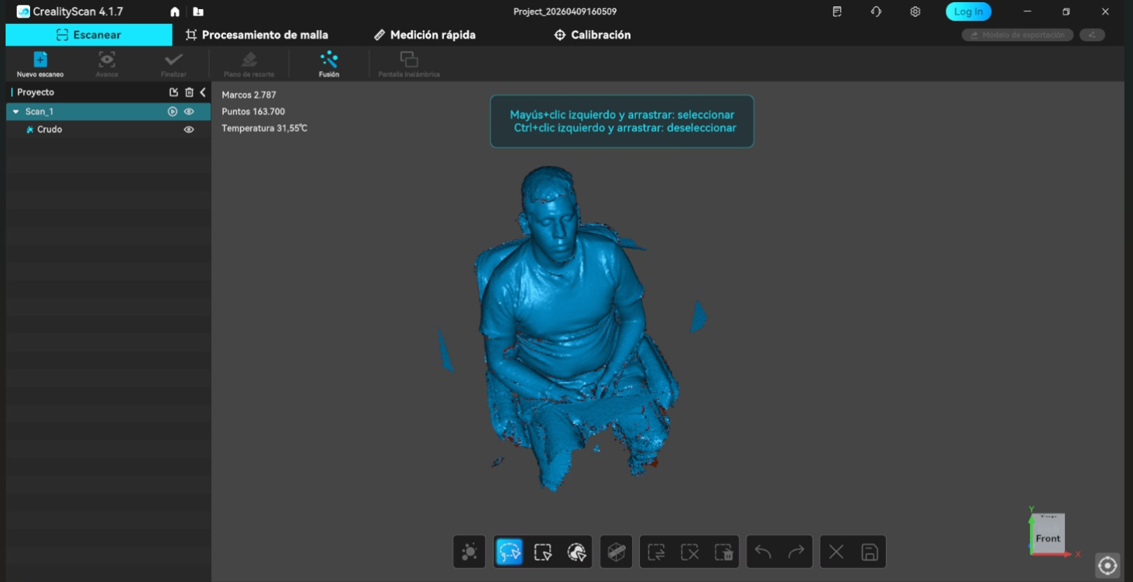
After capture, the mesh needs to be processed. The software can fill holes automatically, but this must be reviewed because automatic hole filling can modify the geometry if it closes missing areas incorrectly. It is also necessary to remove unwanted surfaces such as the table, floor, chair, or nearby objects captured during the process. Finally, the mesh density is checked before exporting because a denser mesh gives more detail but creates a heavier STL file.
Scanning workflow summary
- Prepare the scanning area with stable light and enough space to move around the subject.
- Keep the scanned person as still as possible to avoid distortions in the captured mesh.
- Analyze the surface: dark, shiny, transparent, or reflective objects may require preparation.
- Use talc or a fine matte powder if the object is too shiny or reflective.
- Use the Creality software to monitor the live scan and complete the surface coverage.
- Control the distance between the scanner and the object to avoid red warning zones.
- Review the captured mesh before trimming and exporting the final model.
- Fill holes carefully and check that the automatic repair does not deform the object.
- Clean and crop the final result so the exported bust is easier to use later.
- Export the final model as STL for later 3D printing.
10. Scan Quality, Limitations, and Comparison
10.1 Scan quality evaluation
The final scanned bust was close to the real object in overall shape and volume. The main forms of the head, face, shoulders, and general silhouette were captured successfully. The quality of the scan depends on the scanner, the lighting, the operator movement, the surface properties, and how much time is spent covering difficult areas.
| Aspect | Evaluation |
|---|---|
| General shape | Good approximation of the real bust and body volume. |
| Precision | Good for a visual and printable bust, although exact accuracy depends on distance and tracking quality. |
| Noise | Some noise can appear in areas with weak tracking, movement, or difficult surface conditions. |
| Missing areas | Possible in hidden zones, undercuts, hair, or areas not reached by the scanner angle. |
| Mesh quality | Usable for 3D printing after trimming, cleaning, and hole filling. |
10.2 Scanning limitations
3D scanning is very useful, but it is not automatic perfection. The scan quality depends on preparation and operator control. Lighting is one of the most important factors. Too much light, reflections, or shadows can affect tracking and produce incomplete geometry.
Surface properties also matter. Very dark, shiny, transparent, or reflective surfaces are harder to capture because the scanner may not detect stable surface information. In those cases, a fine matte powder such as talc can help reduce reflection, but it must be applied lightly so it does not add unwanted texture or change the shape.
Geometry also affects scanning. Deep holes, undercuts, hidden surfaces, and thin features may not be captured completely if the scanner cannot see them from enough angles. For people, movement is another limitation: even small movement can deform the scan or create duplicated geometry.
10.3 Real object vs scanned model
Compared with the real subject, the scanned model kept the main proportions and overall appearance. The result was good enough to be exported as STL and printed as a physical bust. However, some fine details can be softened during capture, mesh processing, or hole filling.
The difference between the real object and the scanned model depends mainly on scanner precision, surface conditions, lighting, and the operator’s movement. In this case, the result was useful for digital reproduction and 3D printing, but it is important to understand that a scan usually requires cleanup before it becomes a final fabrication-ready model.
11. Quick Notes on Scanning
- Good lighting helps the scanner maintain more stable tracking.
- An open area makes it easier to move around the subject during capture.
- The subject should remain still so the final mesh does not deform.
- The scanner distance must be controlled during the full capture process.
- Shiny, dark, transparent, or reflective surfaces may require surface preparation.
- Scanning is useful for reverse engineering, documentation, and reproducing existing forms.
12. Reflection
- The group assignment was useful because it helped define the practical limits of the printers before working on my own model. Understanding overhangs, bridges, supports, and tolerances helped me prepare the train more realistically.
- This assignment helped me understand why additive manufacturing is not only a prototyping tool, but also a process that enables geometries that are not easy to create with subtractive manufacturing.
- The section cuts in Inventor were very useful because they allowed me to justify why the train model is suitable for 3D printing. The internal spherical feature and enclosed internal geometry would be very difficult to machine directly with CNC.
- Comparing FDM and resin printing showed me that each technology has a different purpose. FDM is practical, fast, and accessible, while resin gives much better detail but requires more post-processing.
- I learned that print orientation and supports are as important as the model itself. A good design can fail if it is printed in a poor orientation or without proper support planning.
- The tolerance evaluation is important for future assemblies. For moving parts or inserted components, around 0.2 mm of clearance is a practical starting point, but it must always be tested depending on the printer and material.
- The scanning process showed me that 3D scanning is not only pressing a button. It requires object preparation, stable lighting, correct distance, surface evaluation, and careful operator movement.
- I also learned that mesh cleanup is an essential part of scanning. Filling holes, removing unwanted surfaces, and checking the mesh density directly affect whether the final STL is useful for printing.
- The comparison between the real object and the scanned model helped me understand the strengths and limitations of scanning. The general shape can be captured very well, but small details may be lost or smoothed.
- Overall, this week helped me decide when to use 3D printing, when scanning is useful, and how both technologies can support the development of future parts for my final project.