Week 16
System Integration
Integrating the mechanical structure, electronics, embedded programming, WiFi communication, Blynk dashboard and packaging of Fab Train as a finished final project.
1. Checklist
- ✅ Made a plan for system integration for my final project
- ✅ Documented the integration plan with diagrams, sketches and system architecture
- ✅ Implemented packaging methods for the final project
- ✅ Designed the final project to look like a finished product
- ✅ Documented the integration of the mechanical, electronic and digital systems
- ✅ Documented the train, station, dashboard and packaging integration
- ✅ Tested the system integration as a complete Fab Train kit
- ✅ Linked the system integration documentation from the final project page
2. System Integration Overview
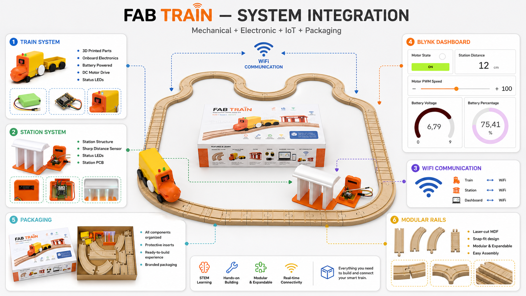
The goal of this assignment was to define, apply and document the system integration of my final project. My final project is called Fab Train, an interactive STEM train kit that combines a modular rail circuit, a 3D printed train, a smart station, custom electronics, WiFi communication, a Blynk dashboard and a final packaging system.
Fab Train is not only a collection of separate parts. The project works as an integrated system where mechanical design, electronics, programming, communication, interface design and packaging are connected to create a finished educational product.
The system was documented as completed. The train moves on the wooden rail circuit, the station detects the train with the Sharp sensor, the train and station communicate through WiFi, the Blynk dashboard visualizes the data, and the packaging contains the complete kit.
3. Integration Plan
Before integrating the final project, I divided the system into smaller subsystems. This helped me understand how each part should connect with the others and what needed to be tested before the final assembly.
| Subsystem | Main elements | Integration objective |
|---|---|---|
| Mechanical system | MDF rails, 3D printed train, wagon, wheels and station structure | Make the train move correctly on the rail circuit and interact physically with the station. |
| Train electronics | XIAO ESP32-C6, PCB, motor driver, DC motor, LEDs, battery reading and switch | Control movement, LEDs and battery monitoring inside the train. |
| Station electronics | XIAO ESP32-C6, station PCB, Sharp distance sensor, LEDs and 5 V power input | Detect when the train arrives at the station and update the system state. |
| Communication | WiFi connection and Blynk datastreams | Connect train and station data to the same dashboard and allow user interaction. |
| Dashboard | Blynk panel, widgets and virtual pins | Visualize motor, LEDs, distance, battery and speed values. |
| Packaging | Rectangular box, vinyl graphics and internal arrangement | Store all project elements and make the project look like a finished educational kit. |
4. Final System Architecture
The final architecture is based on two connected devices: the train and the station. Both use a XIAO ESP32-C6 and communicate through WiFi. The train contains the motor and battery system. The station contains the Sharp distance sensor and station LEDs. Both devices send and receive data through Blynk.
| System block | Components | Function |
|---|---|---|
| Train system | XIAO ESP32-C6, L9110S motor driver, DC motor, LEDs, battery voltage divider and 9 V battery | Moves the train, controls LEDs, monitors battery and responds to Blynk commands. |
| Station system | XIAO ESP32-C6, Sharp distance sensor, LEDs, station PCB and 5 V external supply | Detects train arrival, updates distance value and activates the stop state. |
| Communication layer | WiFi and Blynk virtual pins | Allows both devices to be visualized and controlled from the same dashboard. |
| User interface | Blynk dashboard with button, gauges, indicators and slider | Allows the user to start the train, continue after the station stop and adjust speed. |
| Physical product | Rails, train, wagon, station and packaging | Presents the project as a complete STEM educational kit. |
The system logic can be summarized as follows:
- The user assembles the rail circuit.
- The user places the station near the rail path.
- The user places the train and wagon on the rails.
- The train is powered by a 9 V battery and turned on with its switch.
- The station is powered with an external 5 V supply connected to the 5 V pin of the XIAO circuit.
- The train and station connect through WiFi and update the Blynk dashboard.
- The user starts the train from the Blynk button.
- When the station detects the train between 10 cm and 15 cm, the stop state is activated.
- The train stops at the station.
- The user presses the Blynk button again to continue the route.
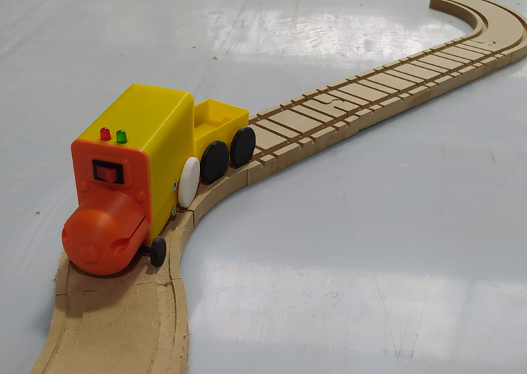
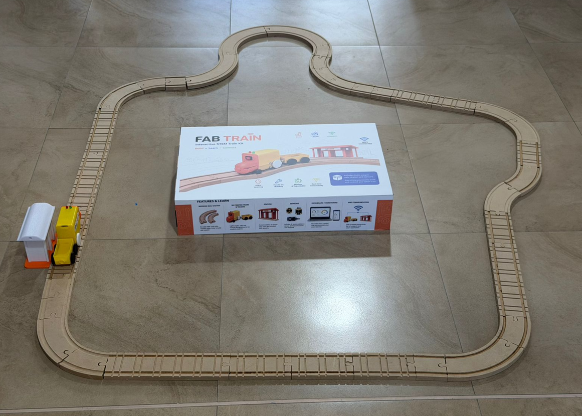
5. Mechanical Integration
The mechanical integration connects the MDF rail system with the 3D printed train, wagon and station. The rails were designed as modular pieces so the user can assemble different paths according to their preference.
The rail system includes straight sections, curved sections and bifurcation pieces. The train wheels were designed according to the rail geometry so the train can move through the circuit without leaving the track.
The wagon is coupled to the locomotive and follows the same rail path. The station is positioned next to the track so the Sharp sensor can detect the train when it arrives.
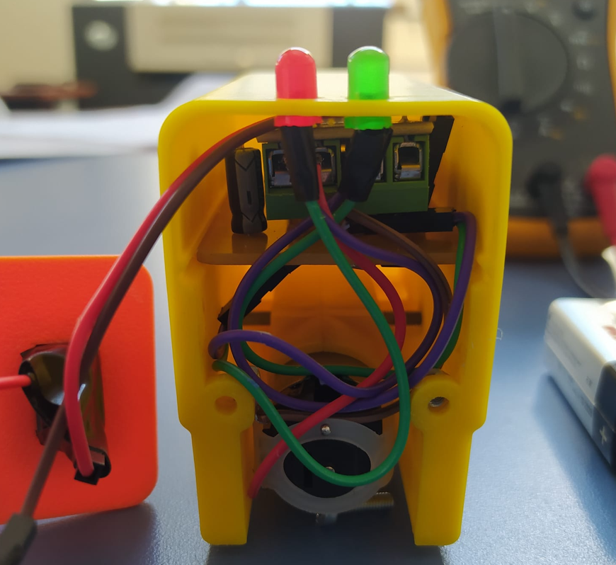
6. Train Electronic Integration
The train includes its own internal electronics. The objective was to make the electronics compact enough to fit inside the 3D printed locomotive while still allowing motor control, LED control and battery monitoring.
The train PCB integrates a XIAO ESP32-C6, an L9110S H-bridge motor driver, a DC motor, LEDs, a switch, a voltage regulation system and a voltage divider for the battery reading. The voltage divider is important because the battery voltage is higher than the safe input voltage of the microcontroller.
The internal electronics are protected inside the train. The user does not need to touch the electronics during normal use. The user only turns the train on or off and controls the system from the Blynk dashboard.
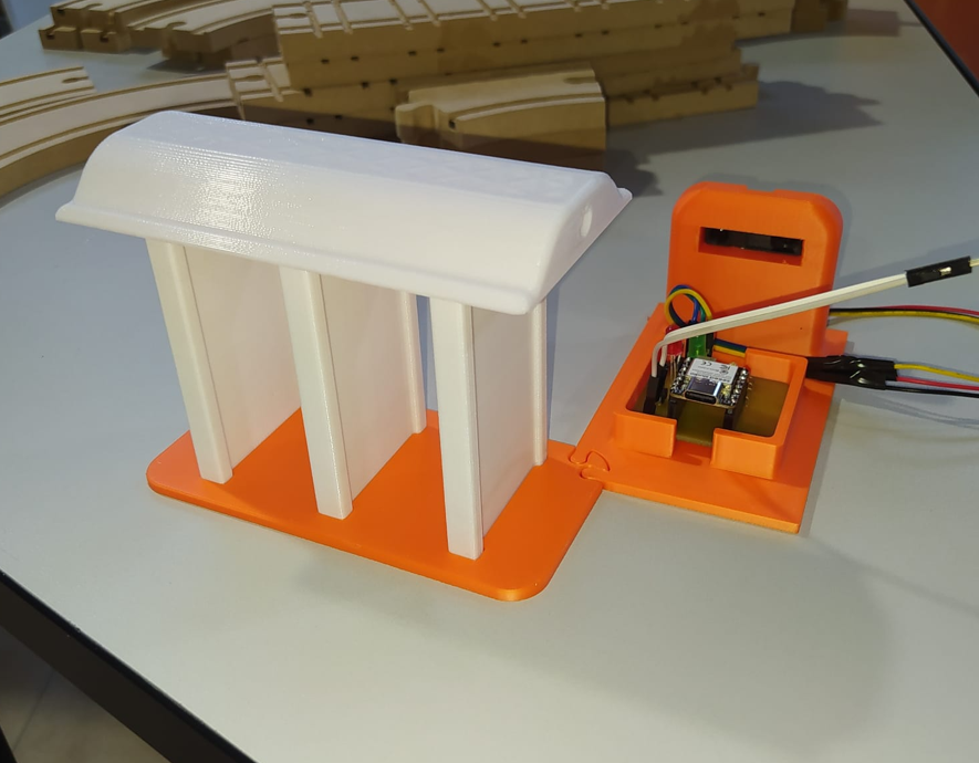
7. Station Integration
The station is the second smart device in the system. It includes a XIAO ESP32-C6, a Sharp distance sensor, LEDs and a custom station PCB. Its main function is to detect when the train arrives at the station and update the system state through Blynk.
The station is powered by an external 5 V power supply. This 5 V input is connected directly to the 5 V pin of the XIAO-based station circuit to power the electronics.
The Sharp sensor is positioned to detect the train when it is approximately between 10 cm and 15 cm from the station. If the detected distance is within this range, the system interprets that the train has arrived. Values below or above that range are interpreted as the train not being correctly positioned at the station.
When the arrival condition is detected, the station activates the stop command. The train stops and waits until the user presses the Blynk button to continue.
8. Power Integration
The power system was separated into two parts: the train power system and the station power system. This separation made the integration easier because the train is mobile, while the station remains fixed.
| Subsystem | Power source | Integration details |
|---|---|---|
| Train | 9 V battery | Powers the train electronics and motor system. The battery voltage is monitored through a voltage divider and displayed in Blynk. |
| Train logic | Regulated voltage | The XIAO ESP32-C6 uses safe logic levels, so voltage regulation and battery reading protection were required. |
| Station | External 5 V supply | The station is powered from an external 5 V source connected to the 5 V pin of the XIAO station circuit. |
| Future improvement | Rechargeable batteries or AC/DC adapter | The train could use a rechargeable battery, and the station could use a regulated AC/DC supply or its own rechargeable battery. |
In a future version, I would improve the power system by replacing the 9 V battery with a rechargeable battery and adding an integrated charging method. For the station, I could design a more robust power system using a regulated AC/DC adapter or a rechargeable battery.
9. Communication Integration
The train and the station communicate using WiFi. Both devices are connected to Blynk, which allows the dashboard to visualize the states of both systems at the same time.
The communication logic is based on state updates. The station detects the train and updates the stop command. The train reads the system state and reacts by stopping or continuing, depending on the user interaction through the Blynk button.
| Event | System action | Dashboard result |
|---|---|---|
| User presses the Blynk button | The train starts moving | Motor state changes to active |
| Train approaches station | Sharp sensor reads the distance | Station distance value updates in Blynk |
| Distance is between 10 cm and 15 cm | Station activates the stop command | Station stop command changes state |
| Stop command is active | The train motor stops | Motor state changes to inactive |
| User presses the Blynk button again | The train continues moving | Motor state changes to active again |
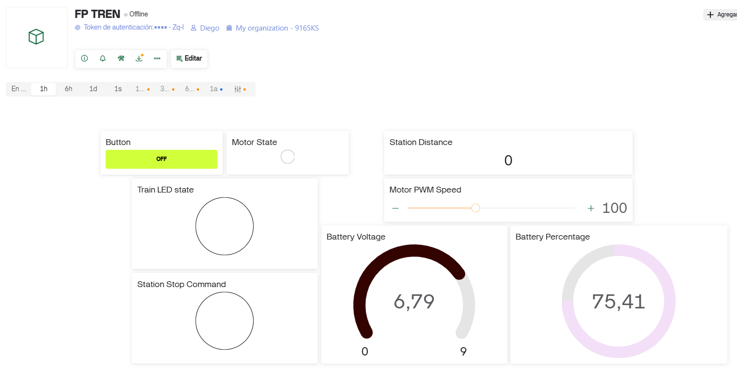
10. Dashboard Integration
The dashboard was created in Blynk. It integrates train and station information in one panel. This helps the user understand the system behavior and also helps during testing and debugging.
The dashboard includes a main button that works as the initial start command and also as the command to resume movement after the train stops at the station.
| Dashboard widget / value | Function |
|---|---|
| Button | Starts the train and allows it to continue after stopping at the station. |
| Motor State | Shows whether the motor is active or inactive. |
| Train LED State | Shows the LED state of the train. |
| Station Stop Command | Shows whether the station has activated the stop condition. |
| Station Distance | Shows the distance measured by the Sharp sensor. |
| Battery Voltage | Shows the voltage of the train battery. |
| Battery Percentage | Shows the estimated battery percentage of the train. |
| Motor PWM Speed | Allows speed adjustment from the dashboard. |
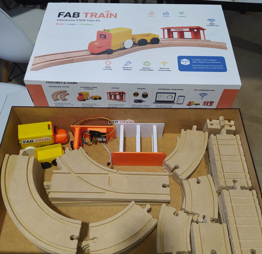
11. Packaging Integration
Packaging was an important part of the system integration because the final project had to look like a finished product, not only like a prototype. I designed and fabricated a rectangular box to store the complete Fab Train kit.
The final box dimensions are 50 cm × 31 cm × 10 cm. The packaging includes the train, wagon, rail pieces and station inside. The box was finished with matte white adhesive vinyl applied on five sides, giving the kit a cleaner and more professional appearance.
The packaging design helps organize the project, protect the components and communicate the educational identity of Fab Train. The internal layout was planned so the user can store the physical parts of the system after use.
12. CAD, Sketches and System Diagrams
To plan the system integration, I used CAD models, fabrication drawings and diagrams. These helped me understand the relationship between physical parts, electronics and user interaction before assembling the final project.
| Design document | Purpose |
|---|---|
| Rail CAD drawings | Defined the geometry, spacing and modular rail connections. |
| Train 3D model | Defined the body, internal volume, wheel placement and mechanical fit. |
| Wagon 3D model | Defined the wagon geometry and its relationship with the rails. |
| Station CAD model | Defined the position of the sensor, LEDs and station structure. |
| PCB schematics and layouts | Defined the electronic connections for the train and station boards. |
| Blynk dashboard configuration | Defined the virtual pins, widgets and data flow between devices. |
| Packaging design | Defined the final box, dimensions, vinyl artwork and internal organization. |
13. Integration Testing
After integrating the subsystems, I tested the project as a complete system. The objective was to verify that each subsystem worked individually and also worked correctly when connected to the rest of the project.
| Test | Expected result | Result |
|---|---|---|
| Rail assembly | The user can assemble the rail circuit freely. | Passed |
| Train movement | The train moves on the MDF rail system. | Passed |
| Wagon integration | The wagon follows the train on the track. | Passed |
| Motor control | The train motor responds to the programmed logic. | Passed |
| Speed control | The motor PWM speed can be adjusted from Blynk. | Passed |
| Battery monitoring | Battery voltage and percentage appear in Blynk. | Passed |
| Station detection | The Sharp sensor detects the train between 10 cm and 15 cm. | Passed |
| Stop command | The station activates the stop state and the train stops. | Passed |
| Resume command | The user presses the Blynk button and the train continues. | Passed |
| Packaging | All main components fit inside the box. | Passed |
14. Problems and Fixes During Integration
System integration helped me identify and solve problems that were not always visible when testing each subsystem separately.
| Problem / challenge | Cause | Solution / decision |
|---|---|---|
| Train fit on the rails | The wheel dimensions and rail geometry had to match correctly. | I adjusted the train and wheel design through 3D printed prototypes. |
| Internal space inside the train | The train body had to contain the PCB, motor, wiring and battery. | I designed the train body considering the internal volume and component placement. |
| Battery voltage reading | The battery voltage was higher than the microcontroller input level. | I used a voltage divider to read the battery safely. |
| Station detection distance | The sensor needed a reliable range to identify when the train arrived. | I defined the station detection range between 10 cm and 15 cm. |
| Station power | The station is fixed and does not need to move with the train. | I used an external 5 V power source for the station. |
| System control logic | The train needed to stop at the station and wait for the user. | I used the Blynk button as the start and resume command. |
| Finished product appearance | The project needed to look like a final product, not only a prototype. | I designed a packaging box with adhesive vinyl and internal storage. |
15. Finished Product Appearance
One of the objectives of this assignment was to make the final project look like a finished product. For this reason, I worked on the physical presentation of the kit, not only on the electronics and mechanical function.
The final kit includes a rectangular box with matte white vinyl graphics, modular rails, the train, wagon and station. The electronics are integrated inside the train and station so the user experience is simple and safe. The user assembles the rails, places the train and station, turns on the system and interacts through Blynk.
16. Final Project Link and Files
This system integration documentation is linked from my final project page. The final project page contains the complete project documentation, while this assignment focuses specifically on how the subsystems were connected and integrated.
The downloadable ZIP file includes the main files used for the integrated system, such as 3D parts, code and packaging files.
17. Reflection
- System integration helped me understand that a final project is not only about making each part work separately. The real challenge is making all parts work together.
- The mechanical design of the rails and wheels was critical because the train movement depends on the physical relationship between both systems.
- The internal space of the train was one of the most important constraints because the electronics, motor, battery and wiring had to fit inside the locomotive body.
- The station integration showed me that sensor position is as important as the code. If the sensor is not placed correctly, the detection logic will not be reliable.
- Defining a detection range between 10 cm and 15 cm helped make the station behavior more controlled and easier to test.
- Blynk was useful not only as a user interface, but also as a debugging tool because I could see the motor state, battery, distance and stop command in real time.
- The power system needs to be considered carefully in any integrated project. The train uses a battery, while the station uses an external 5 V source because it remains fixed.
- A future improvement would be to replace the 9 V battery with a rechargeable battery and design a charging system for the train.
- Packaging changed the perception of the project. With the box, vinyl design and internal organization, Fab Train looks more like a final product and less like a prototype.
- I learned that documentation must explain not only what the project does, but also how the parts are connected and why each integration decision was made.
- The final integration confirmed that Fab Train can work as an educational STEM kit because it combines assembly, electronics, programming, IoT and physical interaction.
- Overall, this assignment helped me transform Fab Train from a set of fabricated parts into a complete system with a clear user experience.