
Week 07
Computer-Controlled Machining
CNC Machining, CAM Workflow, Toolpaths, Tolerances, and Modular Wooden Rail System
1. Checklist
- ✅ Linked to the group assignment page
- ✅ Reflected on lab safety training and CNC operation
- ✅ Documented the design process for CNC machining
- ✅ Documented CAM workflow and toolpath generation
- ✅ Documented CNC machining parameters, tools, feeds, and speeds
- ✅ Machined and assembled a large modular object
- ✅ Included design files and final result documentation
- ✅ Included reflections about the assignment
2. Group Assignment
For the group assignment, we completed the CNC safety training and reviewed the main parameters involved in computer-controlled machining, including tool selection, feeds, speeds, fixturing, materials, and toolpath strategies.
3. Introduction to CNC Machining
Computer-Controlled Machining is a digital fabrication process where a cutting tool removes material following toolpaths generated from a digital design. Unlike laser cutting, where the laser beam cuts through the material without physical contact, CNC machining uses a rotating tool that physically removes material layer by layer.
CNC machining is especially useful for producing larger and stronger parts, working with thicker materials, creating pockets, grooves, profiles, and structural assemblies. This makes it an ideal process for my final project, because the Fab Train requires a wooden modular rail system with functional channels, joints, and pieces large enough to assemble a complete train circuit.
| Aspect | CNC Router | Laser Cutter |
|---|---|---|
| Cutting method | Mechanical material removal with a rotating tool | Thermal cutting using a focused laser beam |
| Material thickness | Works well with thick and structural materials | Better for thin sheets and lighter materials |
| 3D / depth control | Can machine pockets, grooves, reliefs, and 2.5D operations | Mainly 2D cutting and engraving |
| Kerf / tool width | Depends on the diameter of the cutting tool | Depends on the laser beam and material |
| Typical use | Furniture, molds, structures, large parts | Prototypes, engraving, press-fit kits, thin parts |
4. CNC Machine Used
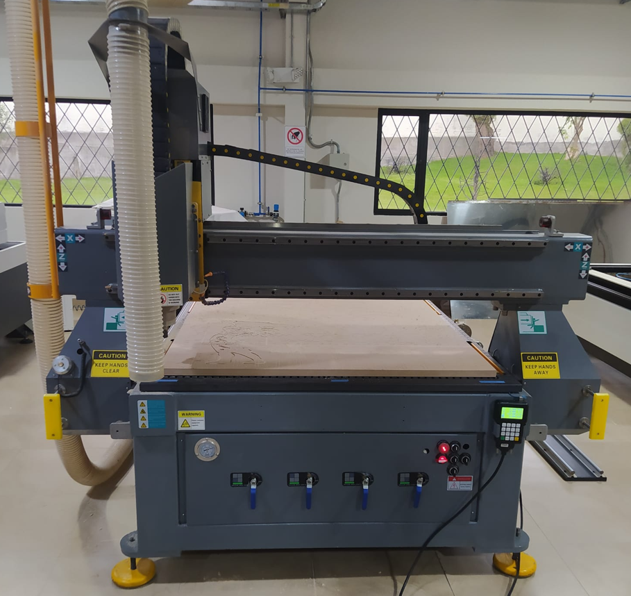
The CNC machine available in the laboratory is an industrial format router with 3 axes plus a fourth rotary axis. The working area in X and Y is 1250 mm × 2500 mm, which allows machining large boards and producing parts at a real structural scale.
This machine is mainly used for materials such as MDF, plywood, pine, PVC, foam, and other machinable soft materials. It is not intended for metal or very hard materials because the system does not include direct coolant on the workpiece. Without proper cooling, metal machining could overheat the tool, damage the material, and reduce the lifetime of the spindle and cutting tool.
5. Common CNC Tools
Tool selection is one of the most important decisions in CNC machining. Each type of tool affects the finish, chip evacuation, cutting direction, material behavior, and machining strategy.
| Tool Type | Main Use | Typical Application |
|---|---|---|
| Straight End Mill | General cutting and profiling | Basic cuts in wood, MDF, and plastics |
| Upcut End Mill | Pulls chips upward | Good chip evacuation, but can leave rougher top edges |
| Downcut End Mill | Pushes chips downward | Cleaner top finish, useful for plywood and laminated surfaces |
| Compression Bit | Combines upcut and downcut behavior | Clean top and bottom edges in sheet materials |
| V-Bit 45°, 60°, 90° | Engraving and chamfering | Text, signs, decorative grooves, and bevels |
| Ball Nose | Rounded tip for 3D surfaces | Reliefs, molds, and smooth 3D surfaces |
| Tapered Ball Nose | Fine 3D carving | Detailed reliefs and small curved features |
| Drill Bit | Vertical drilling | Holes for screws, alignment, and fixturing |
6. Machine Accuracy and Tolerance Test
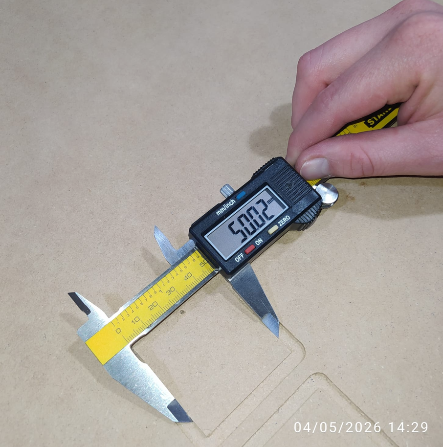
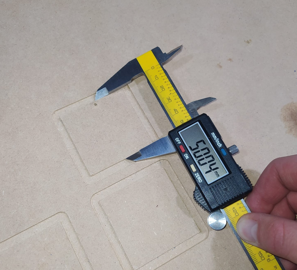
Before machining the final rail system, it was important to understand the real behavior and tolerance of the machine. For this test, I used a 6 mm end mill, which was measured with a digital caliper and showed an actual diameter of 5.98 mm.
A square of 50 mm × 50 mm was machined and then measured in X and Y using a caliper. The Z axis was also checked by machining a programmed depth of 2 mm and measuring the final result.
| Axis / Feature | Designed Value | Measured Value | Deviation |
|---|---|---|---|
| X axis | 50.00 mm | 50.02 mm | +0.02 mm |
| Y axis | 50.00 mm | 50.04 mm | +0.04 mm |
| Z depth | 2.00 mm | 2.02 mm | +0.02 mm |
| Tool diameter | 6.00 mm | 5.98 mm | -0.02 mm |
These differences are small, but they are important when designing assemblies, joints, and modular parts. For the Fab Train rails, this information helped me define tolerances for the male and female connectors, especially because the pieces must fit together without being too loose or too tight.
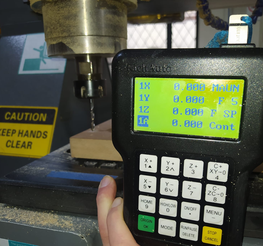
7. CNC Coordinate System and Zero Setting
In CNC machining, it is important to understand the difference between the machine home and the work zero. The machine home is the internal reference position of the CNC, while the work zero is the reference point defined by the user for a specific job on the material.
For this assignment, the work zero was set at the corner of the material and the Z zero was taken from the top surface of the board. This means that all machining depths are calculated from the top of the MDF sheet.
8. Design Development in AutoCAD
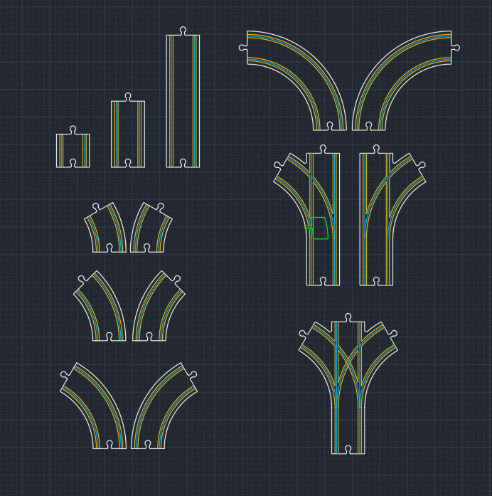
The design for this assignment is directly connected to my final project: a modular wooden rail system for the Fab Train. The goal was to create several types of wooden train tracks that can be assembled in different configurations by the user.
The rail system includes straight sections, curved sections with different angles, and bifurcations. The design also includes male and female connectors so the pieces can be joined together. The female connector was designed with a tolerance of 0.3 mm to improve the fit between parts.
9. CAM Workflow in Aspire Vectric 8.5
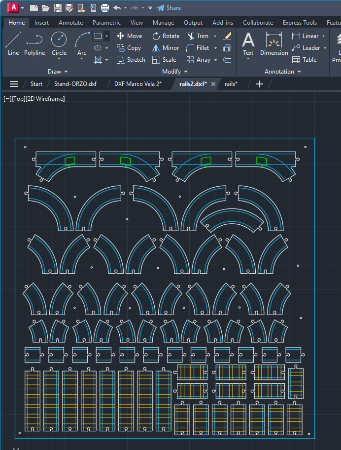
After completing the 2D design in AutoCAD, the file was imported into Aspire Vectric 8.5. This software is used as an intermediate CAM environment to prepare the machining job, define the material, select tools, configure toolpaths, simulate the process, and generate the code that the CNC controller can read.
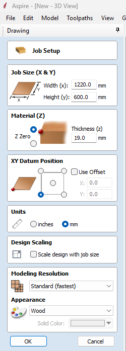
9.1 Job Setup
The first step in Aspire was to define the board dimensions, thickness, Z-zero position, XY origin, and material appearance. In this case, the Z zero was set on top of the material, and the XY origin was located at the lower-left corner of the machining area.
9.2 DXF Import and Layout
The DXF file was imported and placed inside the working area. Aspire provides basic tools to move, rotate, scale, group, join, and edit the vectors before creating the toolpaths.
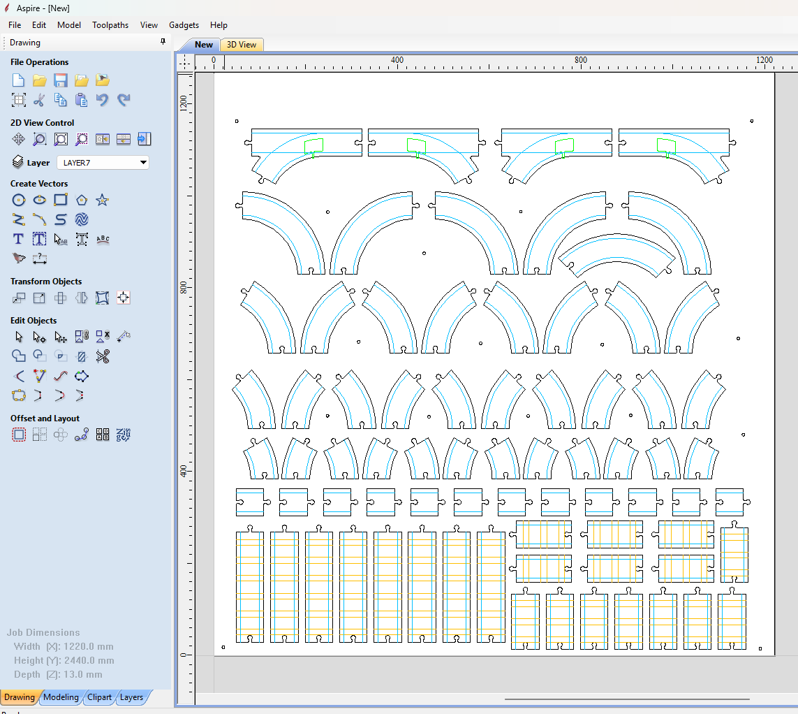
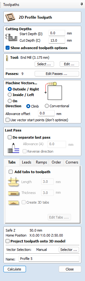
9.3 Toolpath Configuration
The toolpath configuration defines how the CNC will machine each part. This includes selecting the tool, cutting depth, machining strategy, ramps, safe heights, tabs, and whether the tool cuts on the line, inside, or outside the vector.
10. Toolpath Strategy
Each machining operation was exported as a separate file. This allowed the CNC process to be executed in stages, making it easier to control the job, change tools manually, and verify each operation before continuing.
| Operation | Tool | Depth | Purpose |
|---|---|---|---|
| Drilling / marking | 3 mm straight end mill, 2 flutes | 2 mm | Mark screw positions to fixture the MDF board |
| Profile on vector | 3 mm straight end mill, 2 flutes | 3 mm | Create decorative rail board lines |
| Profile on vector | 6 mm upcut end mill, 2 flutes | 6 mm | Machine the train path / rail channel |
| 6 mm upcut end mill, 2 flutes | 4 mm | Create recesses for 3D printed inserts in special rail pieces | |
| Profile outside vector | 3 mm straight end mill, 2 flutes | 12 mm | Final outside cut of each rail piece |
10.1 Machining Parameters
| Tool | RPM | Feed Rate | Pass Depth | Material |
|---|---|---|---|---|
| 3 mm straight end mill, 2 flutes | 18000 RPM | 2500 mm/min | 1.5 mm per pass | MDF 12 mm |
| 6 mm upcut end mill, 2 flutes | 18000 RPM | 3200 mm/min | 2.5 mm per pass | MDF 12 mm |
11. Tabs and Safety During Cutting
Tabs are small uncut bridges that keep the machined pieces attached to the stock material until the job is complete. They are very important for safety because they prevent loose pieces from moving, vibrating, or being thrown by the rotating tool.
For this job, I used tabs with a size of 3 mm wide and 3 mm thick. This made them strong enough to hold the pieces during machining, but easy enough to remove later using a small saw or hand tool.
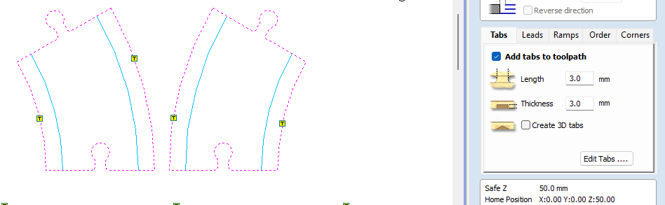
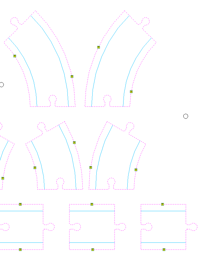
Tabs should be placed in strategic areas, especially on parts that could move during the final contour cut. It is also recommended to place them on straight sections because they are easier to remove and clean after machining.
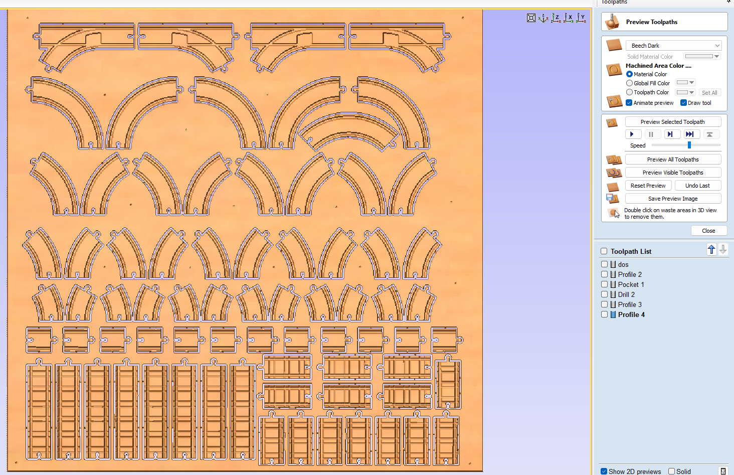
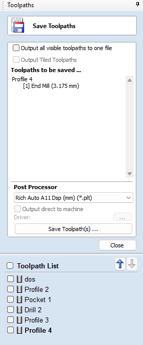
12. Simulation and G-Code Generation
Before machining, Aspire was used to simulate all operations. Simulation is important because it allows checking the final result, detecting possible toolpath errors, and verifying that each operation removes the expected amount of material.
After simulation, the correct CNC post-processor was selected. For this machine, the controller is RichAuto DSP11 mm, which generates a .plt file format for the CNC.
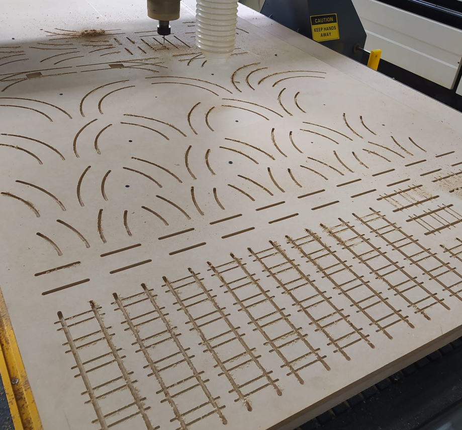
13. CNC Machining Process
The machining process was carried out in stages. First, the material was fixed to the CNC bed using screws. Then each operation was executed separately according to the prepared toolpath files. This staged process made it easier to control the job and manually change between the 3 mm and 6 mm tools.
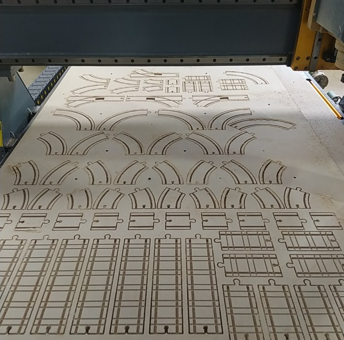
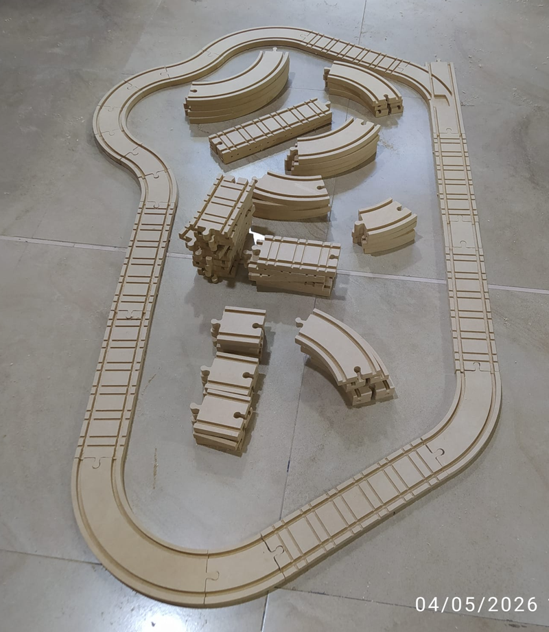
14. Final Result and Assembly
After machining, the tabs were removed and the pieces were cleaned. The final result was a modular wooden rail system that can be assembled in different configurations. This is directly connected to my final project, because these rails will be part of the physical platform for the Fab Train.
The system includes multiple rail types, such as straight pieces, curved pieces, and bifurcations. The modular design allows the user to build different track layouts and test different configurations before defining the final circuit for the complete project.
15. Reflection
- This assignment helped me understand CNC machining as a complete workflow, not only as a cutting process. The result depends on design, CAM setup, tool selection, fixturing, zero setting, safety, and material behavior.
- Safety was one of the most important lessons. A CNC router uses a rotating tool at high speed, so loose parts, bad fixturing, or incorrect parameters can become dangerous for the operator and can also damage the machine or tool.
- Setting the work zero correctly is critical. A small mistake in X, Y, or Z can shift the complete job, cut in the wrong place, or machine deeper than expected. For this reason, I learned to clearly distinguish between machine home and work zero.
- The tolerance test showed that even when the machine is very accurate, small deviations exist. These deviations must be considered when designing assemblies, especially in modular pieces that need to fit together.
- Tool selection has a direct impact on the result. A 3 mm tool allowed me to create smaller details and final profiles, while the 6 mm tool was better for wider channels and material removal.
- I learned that CAM configuration is as important as CAD design. A correct drawing is not enough; the toolpath must define the real cutting strategy, depth, direction, tabs, ramps, and tool behavior.
- Tabs are essential when cutting pieces completely from the board. They prevent parts from moving during machining and reduce the risk of broken tools, damaged pieces, or safety problems.
- Feeds and speeds must be selected according to the tool and material. Some operators also listen to the sound of the machine to detect problems, but this should complement, not replace, the correct calculation of cutting parameters.
- Machining the project in separate files helped me control the process better. Working by stages made it easier to verify each operation and safely change tools between the 3 mm and 6 mm end mills.
- This week was directly useful for my final project because the modular wooden rails are a real physical subsystem of the Fab Train. The assignment was not only a practice exercise, but a functional step toward the final prototype.
- Designing something modular required more attention than a single fixed object. The connectors, tolerances, curves, bifurcations, and assembly logic had to work together so the user can build different rail layouts.
- Overall, this assignment helped me connect digital design with large-format fabrication. It showed me that CNC machining is powerful, but it requires planning, testing, and respect for both the machine and the material.