
Week 09
Input Devices
Reading an Analog Distance Sensor with a Custom XIAO ESP32-C6 Board
1. Checklist
- ✅ Linked to the group assignment page
- ✅ Used a board designed and fabricated for the project workflow
- ✅ Connected an input sensor to a microcontroller board
- ✅ Explained the physical property measured by the sensor
- ✅ Explained the voltage divider used to adapt the sensor signal
- ✅ Read analog values using the ADC
- ✅ Explained how the code works
- ✅ Included original design files and source code
- ✅ Included evidence of the sensor working
- ✅ Included reflections about the assignment
2. Group Assignment
For the group assignment, the lab measured analog levels and digital signals from input devices. This included the use of measurement instruments such as the multimeter and oscilloscope to understand how sensors behave electrically.
This group work was important because input devices do not only produce values in code. They also generate real electrical signals that must be measured, interpreted, and checked before connecting them to a microcontroller.
3. Introduction to Input Devices
Input devices are components that allow a microcontroller to receive information from the physical world. They can detect events, measure variables, or sense changes in the environment. Examples include buttons, potentiometers, temperature sensors, light sensors, distance sensors, Hall effect sensors, microphones, and many others.
Some input devices are digital, which means they usually return only two states, such as HIGH or LOW. A button is a simple example of a digital input. Other sensors are analog, which means they return a variable voltage depending on the physical property being measured. In this assignment, I used an analog distance sensor.
The goal of this assignment was to connect an input sensor to a board that I designed and fabricated, read the sensor values using the XIAO ESP32-C6, and understand how the analog signal changes according to distance. This workflow is directly related to my final project because Fab Train uses a station sensor to detect when the train arrives.
4. Board Used
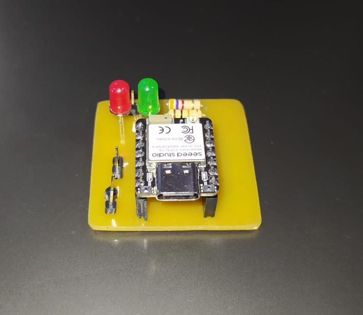
For this assignment, I used a custom PCB designed in EasyEDA and fabricated on single-sided FR4 using a CNC process. The board was created to test input devices with the XIAO ESP32-C6 and to connect the Sharp distance sensor externally.
The board includes a XIAO ESP32-C6, two 5 mm LEDs, two 220 Ω 1/2 W resistors for LED protection, and pin headers to connect the Sharp sensor and the external power supply. This allowed me to test the sensor in a cleaner and more organized way than using only loose jumper wires.
This board also connects the knowledge from previous assignments. The schematic and PCB design process relates to the electronics design week, while the fabrication of the board in FR4 using CNC relates to the electronics production week.
4.1 PCB Design Files
In addition to documenting the custom input device board, I included the downloadable PCB design files so the board can be reviewed, reproduced or fabricated again. The Gerber file contains the fabrication outputs for the PCB, while the PNG file shows the visual PCB layout.
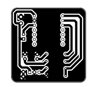
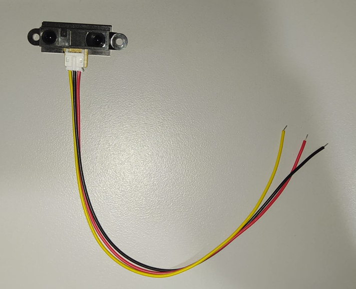
5. Sensor Used: Sharp 2Y0A21 F 3Z
The input device used in this assignment is a Sharp infrared distance sensor from the GP2Y0A21 family. This sensor measures distance using infrared light and outputs an analog voltage that changes according to the distance between the sensor and the object.
Unlike an ultrasonic sensor, which measures distance using sound waves and time of flight, this Sharp sensor uses infrared light and triangulation. This makes it useful for compact applications and short-to-medium distance detection, but its output is not linear. For that reason, the voltage must be interpreted with a conversion equation or calibration curve.
| Parameter | Typical value | Meaning for this assignment |
|---|---|---|
| Sensor type | Infrared distance sensor | Measures distance using reflected infrared light |
| Output type | Analog voltage | The XIAO reads the signal through an ADC pin |
| Supply voltage | 4.5 V to 5.5 V | The sensor is powered from 5 V |
| Typical current | 30 mA | Important for power planning |
| Measuring range | 10 cm to 80 cm | Useful range for distance readings |
| Output behavior | Non-linear | Requires conversion from voltage to distance |
6. Voltage Divider
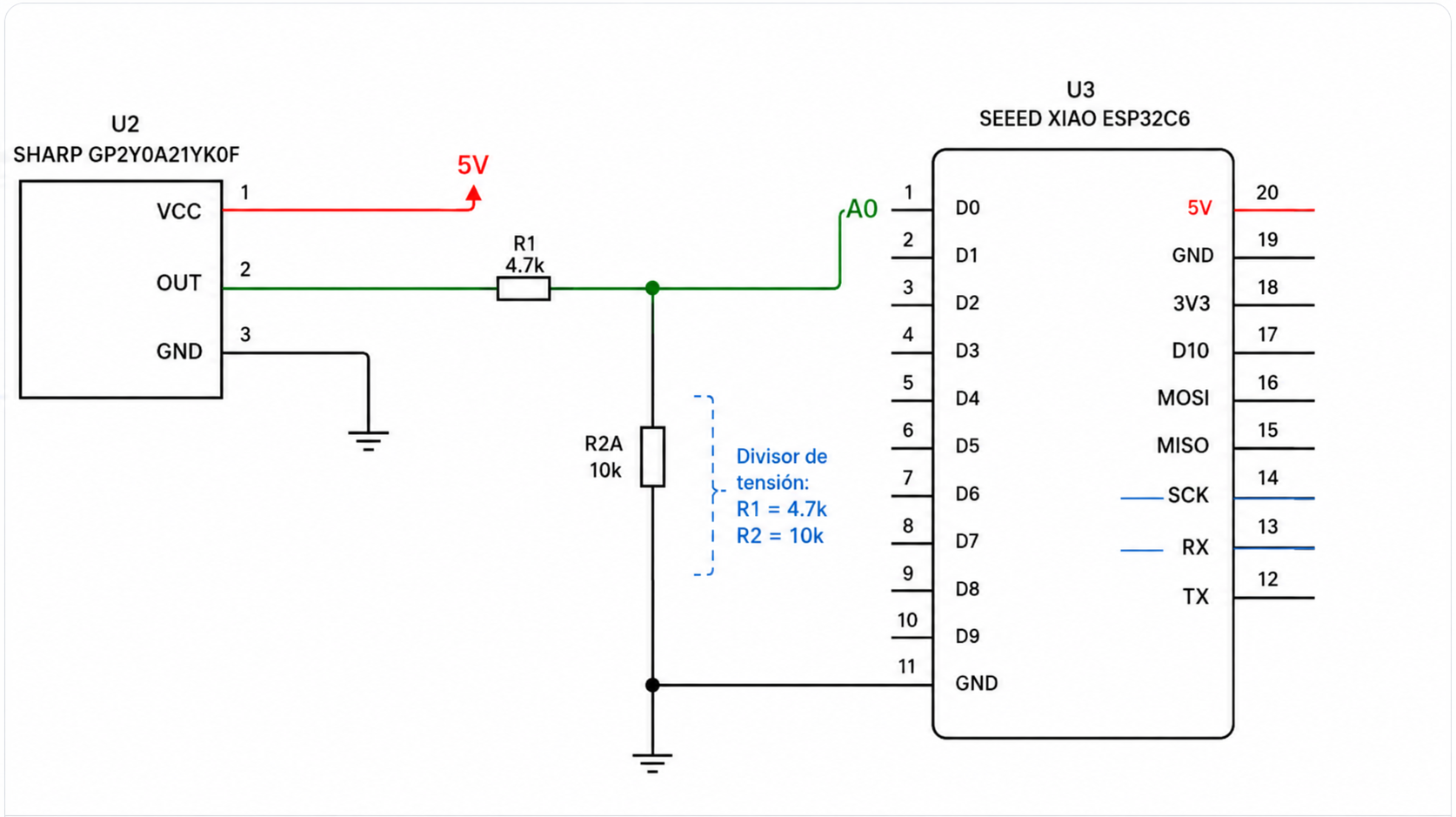
The Sharp sensor is powered from 5 V, while the XIAO ESP32-C6 analog input must work within a safe voltage range. For this reason, the sensor output signal was connected to the XIAO through a voltage divider.
The voltage divider was built with R1 = 4.7 kΩ and R2 = 10 kΩ. The sensor output goes through R1 before reaching the A0 node, and R2 connects that A0 node to ground.
The voltage divider equation is:
Vout = Vin × (R2 / (R1 + R2))

Using:
R1 = 4.7 kΩ
R2 = 10 kΩ

Vout = Vin × (10 / (4.7 + 10))
Vout = Vin × 0.680
This means that the voltage reaching the A0 pin is approximately 68% of the original sensor output voltage. The sensor output itself is analog and normally does not use the full 5 V supply range, but the divider adds protection and adapts the signal for the XIAO ADC input.
In the code, I first calculate the voltage measured at A0, and then I reconstruct the approximate original sensor output voltage using the same voltage divider relationship.
7. Wiring and Schematic
The sensor has three main connections: VCC, GND, and analog output. The sensor is powered from 5 V and GND. The analog output passes through the voltage divider before reaching the XIAO analog input pin A0.
The correct order of the divider is: Sharp sensor OUT to R1 = 4.7 kΩ, then to the A0 node, and from that same node R2 = 10 kΩ goes to GND. This wiring allows the XIAO to read the sensor signal while reducing the voltage at the analog input.
8. ADC Reading
The signal from the Sharp sensor is analog, which means it changes continuously as voltage. However, the microcontroller works digitally. To read an analog signal, the XIAO uses an ADC, or Analog-to-Digital Converter.
The ADC converts the analog voltage into a numeric value. In this code, the ADC resolution is configured to 12 bits, which means the reading goes from 0 to 4095. The code first converts the ADC value into the voltage measured at the A0 pin using a 3.3 V reference.
voltage_A0 = ADC_value × (3.3 / 4095)Since the sensor output passes through a voltage divider, the voltage at A0 is not the same as the original output voltage of the Sharp sensor. To estimate the original sensor output, the code uses the voltage divider equation in reverse:
voltage_sensor = voltage_A0 × ((R1 + R2) / R2)After reconstructing the approximate sensor output voltage, the code uses an approximate equation to convert that voltage into distance in centimeters. Because the Sharp sensor response is non-linear, this value is an estimate and can be improved with calibration measurements.
9. Arduino Code
The code reads the analog value from pin A0, averages several samples to make the signal more stable, converts the ADC value to the voltage at A0, reconstructs the approximate original sensor output voltage using the voltage divider equation, and finally estimates the distance in centimeters. The result is printed in a format compatible with the Arduino Serial Plotter.
const int PIN_SHARP = A0;

// ESP32 ADC configuration
const float VOLTAJE_REFERENCIA = 3.3;
const int ADC_MAX = 4095;

// Voltage divider:
// Sharp OUT ---- R1 4.7k ---- A0 ---- R2 10k ---- GND
const float R1 = 4700.0;
const float R2 = 10000.0;

// Adjust this interval for a faster or slower graph
const unsigned long INTERVALO_LECTURA = 50; // ms

unsigned long tiempoAnterior = 0;

// Simple average to stabilize reading
int leerPromedioADC(int pin, int muestras) {
  long suma = 0;

  for (int i = 0; i < muestras; i++) {
    suma += analogRead(pin);
    delay(2);
  }

  return suma / muestras;
}

// Convert the voltage at A0 back to the original Sharp sensor output voltage
float calcularVoltajeSensor(float voltajeA0) {
  float voltajeSensor = voltajeA0 * ((R1 + R2) / R2);
  return voltajeSensor;
}

float calcularDistanciaCM(float voltajeSensor) {
  if (voltajeSensor <= 0.1) {
    return -1;
  }

  // Approximate curve used for the Sharp sensor
  float distancia = 27.86 / (voltajeSensor - 0.1);

  return distancia;
}

void setup() {
  Serial.begin(115200);
  delay(3000);

  analogReadResolution(12); // 0 to 4095

  Serial.println("ADC\tVoltaje_A0\tVoltaje_Sensor\tDistancia_cm");
}

void loop() {
  unsigned long tiempoActual = millis();

  if (tiempoActual - tiempoAnterior >= INTERVALO_LECTURA) {
    tiempoAnterior = tiempoActual;

    int lecturaADC = leerPromedioADC(PIN_SHARP, 10);

    float voltajeA0 = lecturaADC * (VOLTAJE_REFERENCIA / ADC_MAX);
    float voltajeSensor = calcularVoltajeSensor(voltajeA0);
    float distanciaCM = calcularDistanciaCM(voltajeSensor);

    // Serial Plotter compatible format
    Serial.print("ADC:");
    Serial.print(lecturaADC);

    Serial.print("\tVoltaje_A0:");
    Serial.print(voltajeA0, 3);

    Serial.print("\tVoltaje_Sensor:");
    Serial.print(voltajeSensor, 3);

    Serial.print("\tDistancia_cm:");
    Serial.println(distanciaCM, 2);
  }
}10. Sensor Assembly
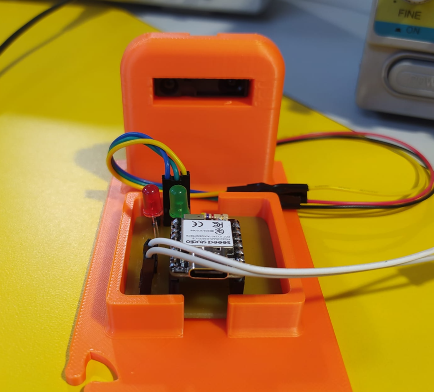
After preparing the board and the voltage divider, I connected the Sharp sensor to the custom XIAO ESP32-C6 board. The external pin headers allowed me to connect the sensor VCC, GND, and analog output signal in a clear way.
The sensor output was connected to A0 through the voltage divider, while the sensor was powered from the external 5 V supply. This setup allowed me to test the sensor safely and observe how the analog value changed when an object moved in front of it.
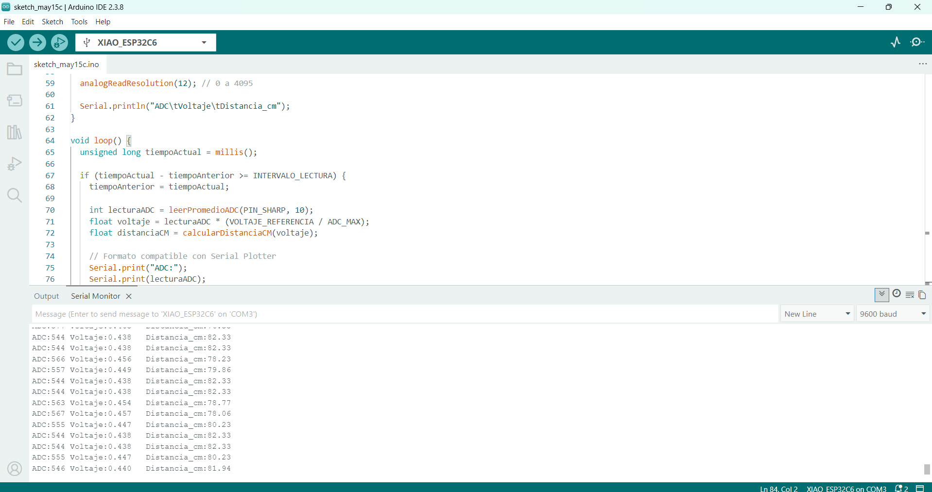
11. Serial Readings
After uploading the code, I opened the Serial Monitor and Serial Plotter to verify that the sensor was reading values correctly. The output includes the ADC value, the voltage measured at A0, the reconstructed sensor voltage, and the estimated distance in centimeters.
The readings change when an object moves closer or farther from the sensor. This confirms that the analog signal is being correctly received by the XIAO and converted into numerical data.
12. Functional Test
The final functional test consisted of moving an object in front of the Sharp sensor and observing how the readings changed in real time. This demonstrates that the sensor is working as an input device and that the microcontroller is correctly reading the analog signal.
13. Problems and Fixes
- The Sharp sensor works with a 5 V supply, while the XIAO analog input must be protected. This was solved by adding a voltage divider before A0.
- The voltage divider was updated to use R1 = 4.7 kΩ and R2 = 10 kΩ. The code was also updated to reconstruct the approximate original sensor output voltage before calculating distance.
- The sensor output is not linear, so the distance calculation is an approximation and can be improved with a real calibration curve.
- Analog sensors can be noisy, so the code uses a simple average of 10 samples to stabilize the reading.
- The wiring needed to be checked carefully because wrong power, ground, or signal connections could affect the sensor reading or damage the board.
14. Reflection
- This assignment helped me understand the importance of sensors as the connection between the physical world and the microcontroller.
- I learned that input devices can be digital or analog, and the way they are read depends on the type of signal they produce.
- The Sharp distance sensor was useful because it produces an analog voltage that changes depending on the distance to an object.
- One of the most important lessons was checking voltage compatibility. The sensor is powered from 5 V, but the XIAO reads analog signals within a lower voltage range, so the voltage divider was necessary to adapt the signal.
- The voltage divider helped me understand that electronics is not only about connecting wires, but also about adapting signals safely between different components.
- Updating the divider values to 4.7 kΩ and 10 kΩ also required updating the code, because the voltage measured at A0 is not the original sensor output voltage.
- The ADC is essential when reading analog sensors. It converts a physical voltage into a digital number that can be processed in code.
- The group assignment was useful because measuring analog and digital signals with instruments helps verify that the sensor values are real and electrically correct.
- I learned that analog sensor readings can be noisy, so averaging several samples is a simple but useful method to stabilize the result.
- The distance conversion is an approximation because the Sharp sensor has a non-linear response. A more accurate result would require calibration with real measured distances.
- This assignment connects directly with my final project because Fab Train uses a Sharp distance sensor in the station to detect the arrival of the train.
- Testing the sensor with a custom board designed in EasyEDA and fabricated in FR4 showed the value of connecting electronics design, PCB production, and embedded programming in the same workflow.
- Overall, this week helped me understand how to select, protect, connect, read, and interpret an input device in an embedded system.