
Week 15
Interface and Application Programming
Creating an IoT interface with Blynk to visualize a Sharp distance sensor and control a DC motor and LED using a XIAO ESP32-C6
1. Checklist
- ✅ Linked to the group assignment page
- ✅ Documented my process
- ✅ Explained the user interface that I made and how I did it
- ✅ Explained how my application communicates with my embedded microcontroller board
- ✅ Explained the problems I encountered and how I fixed them
- ✅ Included original source code
- ✅ Included a hero shot of the application running and communicating with my board
- ✅ Wrote an application for the embedded board that I made
- ✅ Interfaced a user with an input device and output devices
- ✅ Used Blynk as an IoT interface and application platform
- ✅ Displayed real-time sensor data and output status on the interface
- ✅ Tested the interface first with a hybrid circuit and then with a fabricated PCB
2. Group Assignment
For the group assignment, we compared different tool options for creating user interfaces and applications that communicate with embedded systems. This helped us understand that there are many possible ways to build an interface, depending on the type of project, the communication protocol, and the level of interaction required.
My individual assignment uses Blynk as the interface platform. Blynk allows the embedded board to communicate with a cloud dashboard through WiFi, making it useful for IoT applications where sensor data and output states need to be visualized remotely.
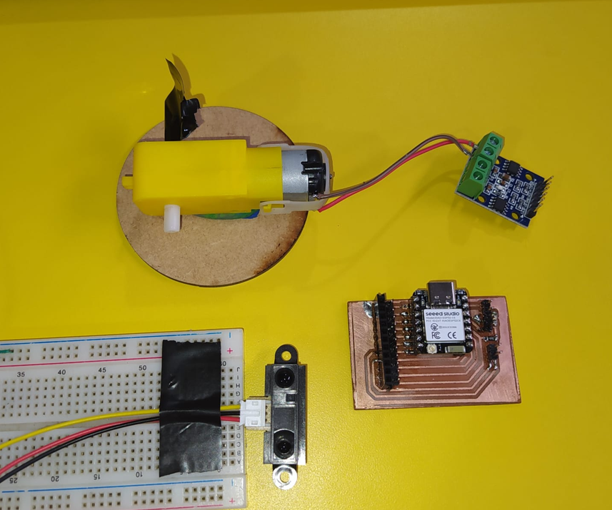
After reviewing the group assignment, I first tested my application with a hybrid circuit using my PCB, a protoboard, the Sharp distance sensor, the L9110S motor driver, a DC motor, and an LED. This first test allowed me to check the input and output behavior with Blynk before moving to the final version. Then, to complete the individual assignment using a fabricated PCB, I repeated the interface test with the definitive PCB where the XIAO ESP32-C6, the L9110S driver, the motor connection, and the SMD LED were integrated.
3. Interface and Application Programming
Interface and application programming is the process of creating a visual or interactive layer that allows a user to communicate with an electronic system. An interface can be a desktop program, a web page, a mobile app, a serial monitor, a local dashboard, or a cloud-based IoT panel.
In embedded systems, an interface is important because it allows the user to understand what the board is doing. Instead of only seeing values in the Serial Monitor, the user can see sensor data, output states, warning messages, buttons, indicators, gauges, and visual feedback in real time.
For this assignment, I created an IoT interface using Blynk. The interface receives data from a Sharp distance sensor and displays it in a dashboard. It also shows if the motor and LED are ON or OFF.
4. IoT, Inputs, and Outputs
The Internet of Things, or IoT, refers to physical devices that are connected to a network and can exchange data with other devices, cloud platforms, or user interfaces. An IoT system usually includes a sensor, a controller, a communication method, an output, and an interface.
In this assignment, the input is a Sharp distance sensor. The sensor measures the distance between the board and an object. The outputs are a red LED and a DC gear motor controlled through an L9110S H-bridge driver.
The XIAO ESP32-C6 reads the sensor, processes the distance value, controls the motor and LED, and sends the information to Blynk using WiFi. This creates a complete interaction between the physical system and the digital interface.
5. Blynk as the User Interface
Blynk is an IoT platform that allows microcontrollers to connect to a cloud dashboard. It provides widgets such as gauges, labels, buttons, switches, charts, and indicators. These widgets are connected to virtual pins, which work as communication channels between the board and the interface.
In this assignment, Blynk was used to visualize the Sharp sensor distance in real time and to show the status of the motor and LED. The interface does not directly control the output manually; instead, it displays what the embedded system decides based on the sensor reading.
The communication path is:
Sharp Sensor → XIAO ESP32-C6 → WiFi → Blynk Cloud → Blynk Dashboard
6. XIAO ESP32-C6 as the Embedded Board
The embedded board used for this assignment is my custom PCB with a XIAO ESP32-C6. This board was developed in a previous assignment and works as a trainer board, allowing me to connect sensors, output devices, and external modules using cables.
The XIAO ESP32-C6 is suitable for IoT applications because it includes WiFi communication. This allows the board to send data to Blynk Cloud and update the dashboard in real time.
For this project, the XIAO reads the Sharp sensor on A0, controls the L9110S motor driver with D1 and D2, and controls the red LED on D10.
7. Project Objective
The objective of this assignment was to write an application for my embedded board that interfaces a user with an input and output devices. I used a Blynk dashboard to show the distance measured by the Sharp sensor and to indicate whether the motor and LED are active.
The logic of the system is based on distance:
| Distance range | Motor state | LED state | Blynk status |
|---|---|---|---|
| 15 cm to 20 cm | ON | ON | Object in range - Motor ON |
| 10 cm to 14 cm | OFF | OFF | Out of range - Motor OFF |
| Less than 10 cm | OFF | OFF | Out of range - Motor OFF |
| More than 21 cm | OFF | OFF | Out of range - Motor OFF |
The motor and LED only turn on when the detected object is between 15 cm and 20 cm.
8. Components Used and Datasheet Reference
Before assembling the system, I reviewed the main characteristics of each component. This is important because the board uses 3.3 V logic, while some external components require 5 V or more current than a microcontroller pin can provide.
| Component | Main characteristics | Role in the assignment | Important consideration |
|---|---|---|---|
| XIAO ESP32-C6 | ESP32-C6 based board with WiFi capability and 3.3 V logic | Main controller and IoT device | Analog and digital pins must not receive unsafe voltage levels |
| Sharp 2Y0A21 F 3Z distance sensor | Analog IR distance sensor, commonly used around 10 cm to 80 cm | Input device connected to A0 | Requires calibration because the output response is nonlinear |
| DC gear motor | DC motor with gearbox for mechanical movement | Output device activated by distance range | Needs external power and should not be connected directly to GPIO |
| L9110S H-bridge driver | Small motor driver module for DC motors | Controls motor using D1 and D2 | Separates motor current from the XIAO pins |
| Red SMD LED 1206 | Visual indicator LED | Output device connected to D10 | Requires current-limiting resistor |
| 499 Ω SMD 1206 resistor | Current-limiting resistor for the LED | Protects the red LED | Limits current through the LED |
| 470 Ω and 1000 Ω resistors | Voltage divider for analog signal | Protects A0 from the Sharp sensor output | Reduces voltage before entering the XIAO analog pin |
9. Electrical Connections
The Sharp distance sensor was connected to the analog pin A0. Since the XIAO ESP32-C6 works with 3.3 V logic and the Sharp sensor is powered with 5 V, I used a voltage divider with 470 Ω and 1000 Ω resistors before the analog input.
The motor was connected to the L9110S H-bridge driver. The driver input pins were connected to D1 and D2. The motor power came from an external 5 V source because motors require more current than a microcontroller GPIO pin can provide safely.
| Connection | XIAO pin / source | Function |
|---|---|---|
| Sharp analog output | A0 | Distance sensor input |
| L9110S IN1 | D1 | Motor control signal |
| L9110S IN2 | D2 | Motor control signal |
| Red LED | D10 | Visual output indicator |
| Motor power | External 5 V source | Power supply for the DC motor |
| GND | Common ground | XIAO, sensor, driver, and external supply must share GND |
9.1 Sharp Sensor Voltage Divider
The voltage divider was used to reduce the analog output voltage from the Sharp sensor before it entered the A0 pin of the XIAO ESP32-C6.
Sharp OUT
   |
  470 Ω
   |
   +------ A0 XIAO ESP32-C6
   |
 1000 Ω
   |
  GND
The approximate divider ratio is:
Vout = Vin × (1000 / (470 + 1000))
Vout = Vin × 0.68
This protects the analog input because the XIAO ESP32-C6 works with 3.3 V logic levels.
9.2 Importance of Common Ground
A common GND is necessary because all signals need the same electrical reference. The XIAO, Sharp sensor, L9110S driver, and external motor power supply must share GND. Without this, the sensor readings and motor control signals may behave incorrectly.
10. Blynk Device
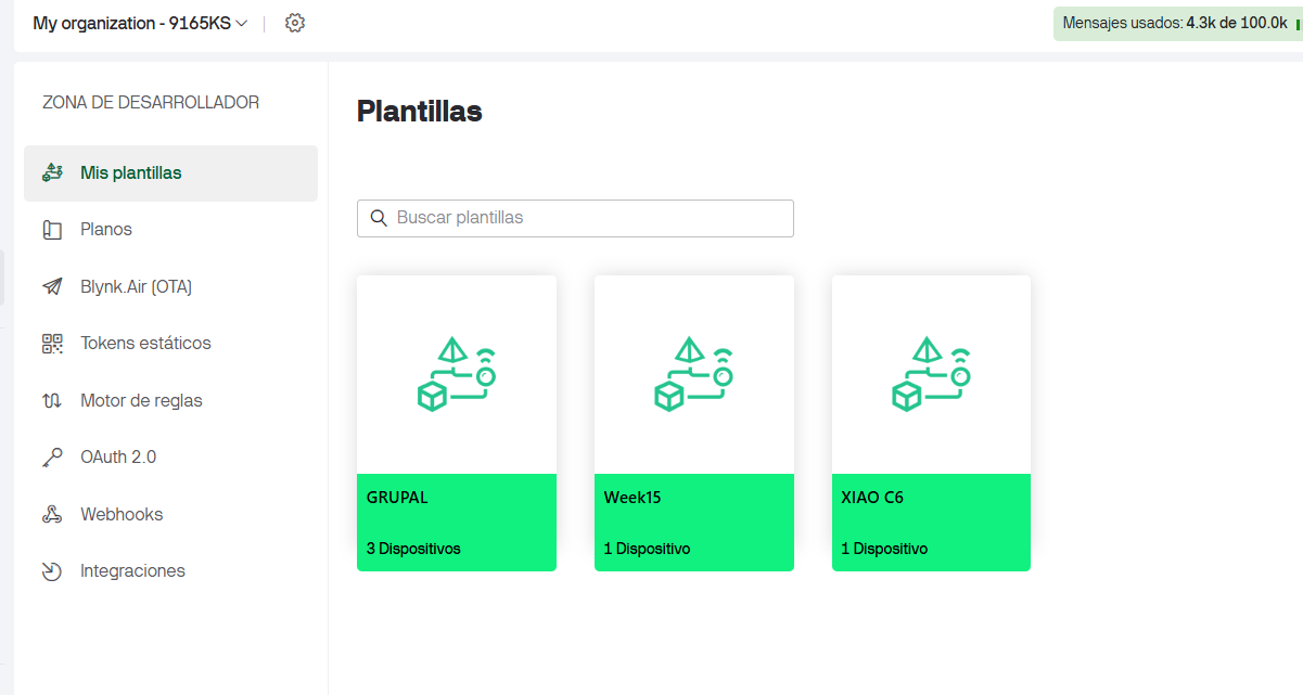
The first step in Blynk was to create an ESP32 device associated with the template named Week15. This device represents the physical XIAO ESP32-C6 board in the Blynk Cloud.
Creating the device is important because Blynk generates the Auth Token. This token is used in the Arduino code so the physical board can authenticate and communicate with the correct device in the Blynk dashboard.
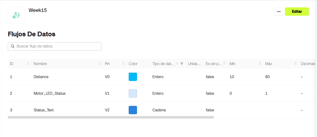
11. Blynk Datastreams
A datastream in Blynk is a virtual channel used to exchange data between the hardware and the dashboard. In this assignment, I created three datastreams: one for distance, one for motor/LED status, and one for a text message.
| Datastream name | Virtual pin | Data type | Minimum | Maximum | Use |
|---|---|---|---|---|---|
| Distance | V0 | Double | 0 | 80 | Displays the Sharp sensor distance in centimeters |
| Motor_LED_Status | V1 | Integer | 0 | 1 | Indicates whether the motor and LED are OFF or ON |
| Status_Text | V2 | String | - | - | Shows a text message with the current system state |
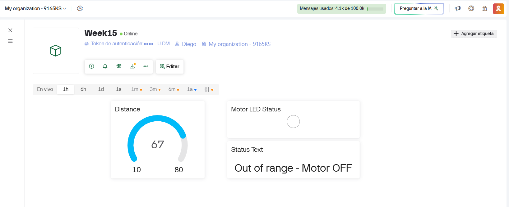
12. Blynk Dashboard
The user interface was created in the Blynk dashboard. I used a radial indicator, a label, and an LED widget. These widgets allow the user to see the measured distance, the state of the output devices, and a text message describing the system condition.
- The radial indicator is connected to V0 and shows the distance in centimeters.
- The LED widget is connected to V1 and turns on when the physical motor and LED are active.
- The label is connected to V2 and shows the current status message.
13. Arduino Code
The code connects the XIAO ESP32-C6 to WiFi and Blynk. The BLYNK_TEMPLATE_ID and BLYNK_TEMPLATE_NAME identify the Blynk template. The BLYNK_AUTH_TOKEN connects the code to the specific device created in Blynk.
It is also necessary to write the WiFi network name and password correctly. Without the correct WiFi credentials, the XIAO cannot connect to the internet or communicate with Blynk Cloud.
For security, the token and WiFi password are hidden in the code shown in the documentation. The real file contains the correct values.
#define BLYNK_PRINT Serial

/************ BLYNK CONFIGURATION ************/

#define BLYNK_TEMPLATE_ID "TMPL2PAhKRuXi"
#define BLYNK_TEMPLATE_NAME "Week15"
#define BLYNK_AUTH_TOKEN "YOUR_BLYNK_AUTH_TOKEN"

/************ LIBRARIES ************/
#include <WiFi.h>
#include <BlynkSimpleEsp32.h>

/************ WIFI DATA ************/
char ssid[] = "YOUR_WIFI_NAME";
char pass[] = "YOUR_WIFI_PASSWORD";

/************ HARDWARE PINS ************/
#define SHARP_PIN A0     // Sharp analog distance sensor
#define MOTOR_IN1 D1     // L9110S input A / IN1
#define MOTOR_IN2 D2     // L9110S input B / IN2
#define LED_PIN   D10    // LED on the PCB

/************ BLYNK TIMER ************/
BlynkTimer timer;

/************ VARIABLES ************/
float distanceCm = 0.0;
int motorState = 0;

float readSharpDistance()
{
  int rawValue = analogRead(SHARP_PIN);

  // ESP32 ADC range is usually 0 to 4095
  float voltage = rawValue * (3.3 / 4095.0);

  // Avoid division problems with very low voltage
  if (voltage < 0.1) {
    return 999.0;
  }

  // Approximate conversion for Sharp IR distance sensor
  float distance = 27.86 * pow(voltage, -1.15);

  return distance;
}

/****************************************************
   Motor control functions
****************************************************/
void motorOn()
{
  digitalWrite(MOTOR_IN1, HIGH);
  digitalWrite(MOTOR_IN2, LOW);

  digitalWrite(LED_PIN, HIGH);

  motorState = 1;
}

void motorOff()
{
  digitalWrite(MOTOR_IN1, LOW);
  digitalWrite(MOTOR_IN2, LOW);

  digitalWrite(LED_PIN, LOW);

  motorState = 0;
}

void updateSystem()
{
  distanceCm = readSharpDistance();

  Serial.print("Distance: ");
  Serial.print(distanceCm);
  Serial.println(" cm");

  if (distanceCm >= 15.0 && distanceCm <= 20.0) {
    motorOn();

    Serial.println("Object detected in range: MOTOR ON / LED ON");

    Blynk.virtualWrite(V2, "Object in range - Motor ON");
  }
  else {
    motorOff();

    Serial.println("Object out of range: MOTOR OFF / LED OFF");

    Blynk.virtualWrite(V2, "Out of range - Motor OFF");
  }

  // Send values to Blynk
  Blynk.virtualWrite(V0, distanceCm);
  Blynk.virtualWrite(V1, motorState);
}

/****************************************************
   SETUP
****************************************************/
void setup()
{
  Serial.begin(115200);
  delay(1000);

  Serial.println();
  Serial.println("====================================");
  Serial.println("XIAO ESP32-C6 + Blynk + Sharp Sensor");
  Serial.println("Input: Sharp sensor on A0");
  Serial.println("Output: Motor L9110S on D1/D2");
  Serial.println("Output: LED on D10");
  Serial.println("====================================");

  pinMode(SHARP_PIN, INPUT);

  pinMode(MOTOR_IN1, OUTPUT);
  pinMode(MOTOR_IN2, OUTPUT);
  pinMode(LED_PIN, OUTPUT);

  motorOff();

  Serial.println("Connecting to WiFi and Blynk...");
  Blynk.begin(BLYNK_AUTH_TOKEN, ssid, pass);

  Serial.println("System ready.");

  // Update system every 500 ms
  timer.setInterval(500L, updateSystem);
}

/****************************************************
   LOOP
****************************************************/
void loop()
{
  Blynk.run();
  timer.run();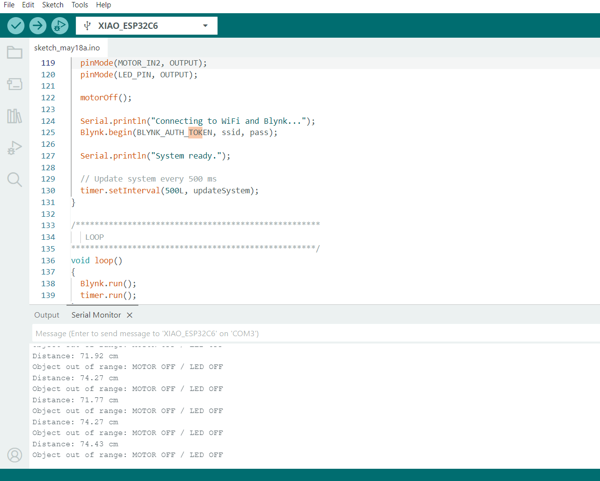
}14. Arduino IDE and Serial Test
After completing the code, I selected XIAO ESP32-C6 in the Arduino IDE and selected the correct serial port. Then I uploaded the program to the board.
The Serial Monitor was used to verify the system behavior. It showed that the board connected to WiFi and Blynk, and it printed the distance values measured by the Sharp sensor.
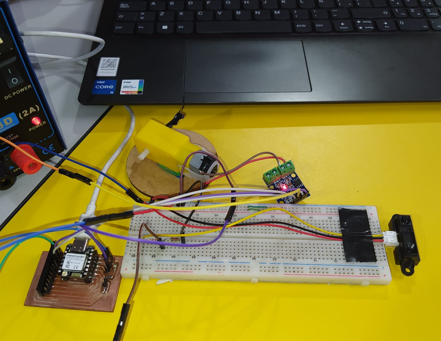
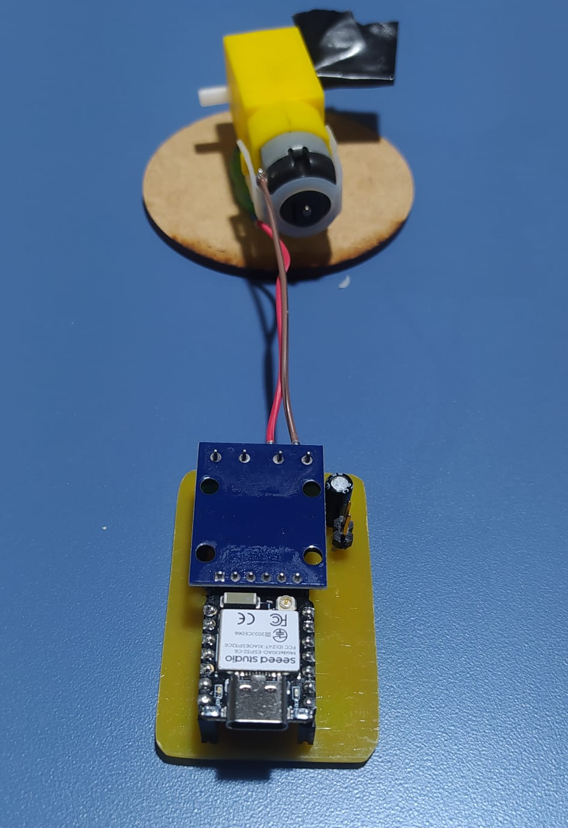
15. Hybrid Circuit Assembly
The first functional test was assembled as a hybrid circuit. In this version, I used my XIAO ESP32-C6 PCB together with a protoboard to connect the Sharp distance sensor, the L9110S motor driver, the DC gear motor, and the LED. This allowed me to test the input and output behavior before moving to the final PCB implementation.
The motor was powered using an external 5 V source. This was important because the DC motor requires more current than the XIAO can safely provide. The XIAO only sends logic signals to the L9110S driver.
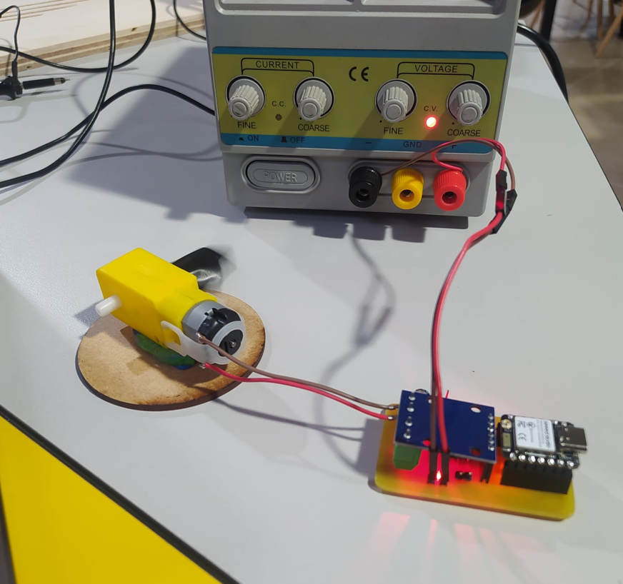
16. Hybrid Functional Test
The first test shows the application running and communicating with the embedded board. When the Sharp sensor detects an object between 15 cm and 20 cm, the motor turns on, the LED turns on, and the Blynk dashboard shows the active state.
When the object is outside that range, the motor and LED turn off, and the dashboard shows that the object is out of range.
17. Final PCB Implementation
After validating the system with the hybrid circuit, I prepared the final version using the fabricated PCB. This version was used to comply with the assignment requirement of working with a board that was fabricated instead of only using a protoboard.
In this final version, the Sharp distance sensor was no longer included. The test focused on the output devices and the Blynk interface: the DC motor controlled by the L9110S H-bridge driver and the SMD LED mounted on the PCB. The XIAO ESP32-C6 communicates with Blynk through WiFi, and the dashboard shows the motor and LED activation while the physical circuit performs the same action.
The fabricated PCB includes the connections for the XIAO ESP32-C6, the motor driver module, the motor output, and the LED indicator. First, I documented both sides of the board before assembling the components.
Then, I mounted the XIAO ESP32-C6, connected the L9110S motor driver module, and connected the DC motor to the PCB. The LED was also included as a visual output indicator, so the interface could activate both the motor and the LED.
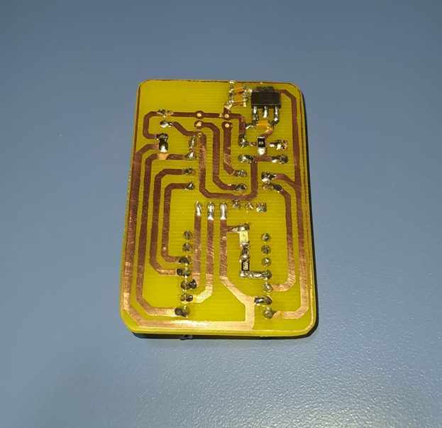
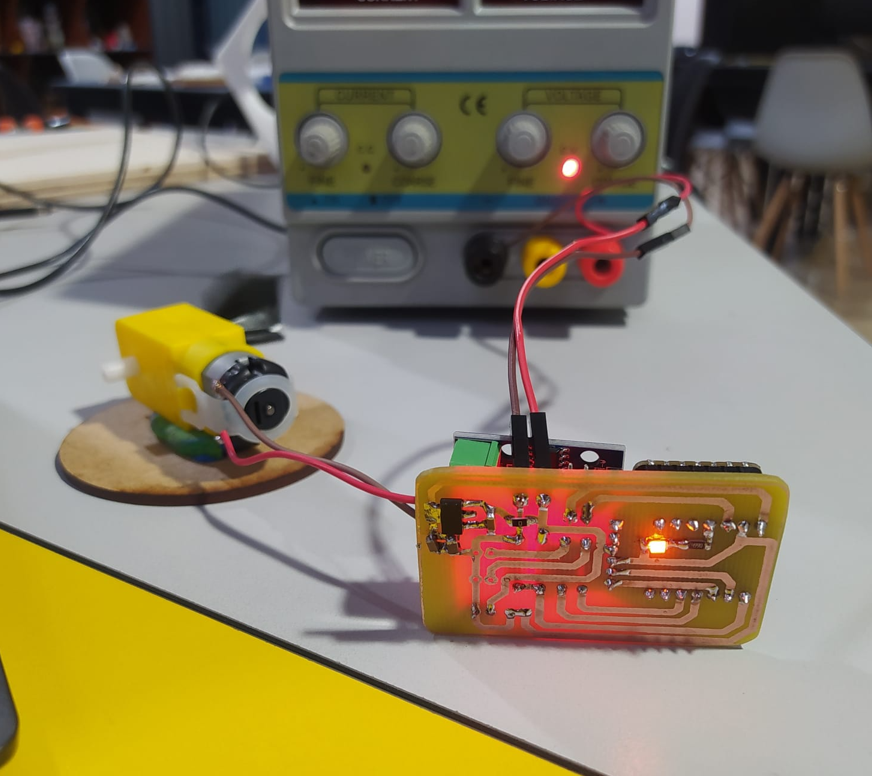
18. Final PCB Power and Output Test
The circuit was powered using an external power supply. This allowed the motor to receive enough current while the XIAO ESP32-C6 controlled the outputs through the L9110S driver. The first view shows the bottom of the PCB while the circuit is operating.
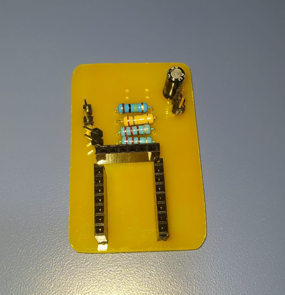
The top view shows the SMD LED mounted on the PCB. This LED turns on together with the motor, giving a clear physical indication that the output state is active.
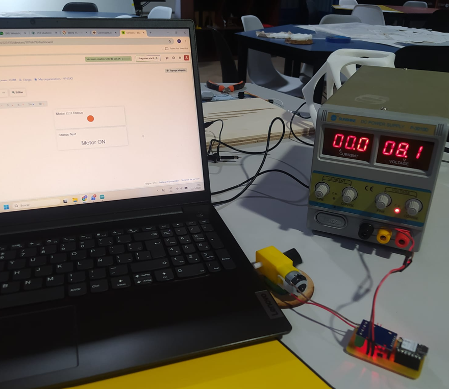
19. Final PCB Blynk Test
Finally, I tested the fabricated PCB with the Blynk dashboard. The XIAO ESP32-C6 connected to WiFi and communicated with the Blynk panel. From the interface, the motor and LED status could be visualized while the physical circuit showed the same behavior.
In the Blynk panel, the motor appears activated and the LED indicator also shows the ON state. At the same time, in the physical circuit, the DC motor turns on and the SMD LED lights up. This confirms that the interface is communicating correctly with the fabricated board.
20. Final PCB Results
- The fabricated PCB allowed the XIAO ESP32-C6, L9110S driver, DC motor, and SMD LED to work together without depending only on a protoboard.
- The Blynk interface communicated correctly with the board through WiFi, and the motor and LED states shown on the dashboard matched the behavior of the physical circuit.
- The SMD LED provided a direct visual reference of the output state on the PCB, making it easier to verify when the system was active.
21. Problems and Fixes
- The Sharp sensor works with 5 V, while the XIAO ESP32-C6 uses 3.3 V logic. I fixed this by adding a voltage divider before the A0 input.
- The DC motor requires more current than a GPIO pin can provide. I fixed this by using the L9110S H-bridge driver and an external 5 V supply.
- The Blynk token must match the correct device. If the token is wrong, the interface will not communicate with the board.
- The WiFi SSID and password must be written correctly. Any typo can stop the board from connecting to Blynk.
- All grounds must be connected together. Without common GND, the sensor readings and motor driver signals may not work correctly.
- The Sharp sensor output is nonlinear, so the distance calculation is an approximation and may require calibration for better accuracy.
- In the final PCB test, I had to verify the board orientation and the connections between the XIAO ESP32-C6, the L9110S module, and the motor output before powering the circuit.
22. Reflection
- This assignment helped me understand how a user interface can make an embedded system easier to monitor and understand.
- I learned that Blynk is useful for IoT projects because it connects hardware to a dashboard without needing to build a complete app from zero.
- I understood the difference between a physical pin and a virtual pin. A0, D1, D2, and D10 are physical pins, while V0, V1, and V2 are Blynk communication channels.
- The Auth Token is essential because it identifies the correct device in the Blynk Cloud. If it does not match, the board and interface cannot communicate.
- The project showed me that input and output devices can be combined to create an interactive behavior: the sensor detects distance and the motor and LED react automatically.
- I learned that voltage levels are very important. The XIAO ESP32-C6 uses 3.3 V logic, so the Sharp sensor signal needed a voltage divider before entering A0.
- Using a motor driver is necessary because a motor cannot be powered directly from a microcontroller pin. The L9110S handles the motor current.
- Common ground is critical. The XIAO, Sharp sensor, motor driver, and external 5 V supply must share GND so the circuit has the same reference.
- The Blynk dashboard helped visualize the system in real time. Seeing the distance, status message, and LED widget made debugging easier.
- The Sharp sensor needs calibration because its analog output is nonlinear. A future improvement would be to create a calibration table using real measured distances.
- This assignment showed the potential of IoT systems for remote monitoring, automation, and interactive control.
- I learned that interface design is not only visual design. It also depends on correct data mapping, virtual pin configuration, communication stability, and clear feedback for the user.
- Testing the sensor, motor, LED, WiFi, and Blynk dashboard separately made the final integration easier and more reliable.
- Using the fabricated PCB helped me validate the system in a more complete way, because the final test was no longer based only on a protoboard but on a board designed and assembled for the assignment.
- Overall, this week helped me connect hardware, software, communication, and interface design into one functional embedded system.