
Week 10
Output Devices
Controlling a DC Gear Motor with a XIAO ESP32-C6 and an L9110S H-Bridge Driver
1. Checklist
- ✅ Linked to the group assignment page
- ✅ Documented the output device used in this assignment
- ✅ Used a microcontroller board designed in a previous assignment
- ✅ Connected an external output device to the XIAO ESP32-C6
- ✅ Used a motor driver to control the DC motor safely
- ✅ Explained how the code works
- ✅ Included the source code and downloadable file
- ✅ Demonstrated the output device working
- ✅ Reflected on output devices, current, power, and safety
2. Group Assignment
For the group assignment, the lab measured the power consumption of output devices. This is important because output devices usually require more current than input devices, and their electrical behavior must be measured before integrating them into a final system.
Measuring voltage, current, and power helps determine if a device can be powered directly from a board or if it requires an external power supply, driver, thicker wires, or wider PCB traces.
3. Introduction to Output Devices
Output devices are components that allow a microcontroller to act on the physical world. Unlike input devices, which read information from the environment, output devices receive commands from the microcontroller and produce an action such as light, sound, motion, heat, or mechanical force.
Common output devices include LEDs, buzzers, relays, displays, servo motors, DC motors, stepper motors, solenoids, and heaters. Each one has different electrical requirements. For example, an LED can usually be controlled with a simple resistor and a digital pin, but a motor needs more current and must be controlled using a driver circuit.
When working with output devices, it is important to consider voltage, current, power consumption, heat generation, current spikes, and possible electrical noise. Motors are especially important because they can generate current peaks during startup and can introduce noise or voltage drops in the circuit.
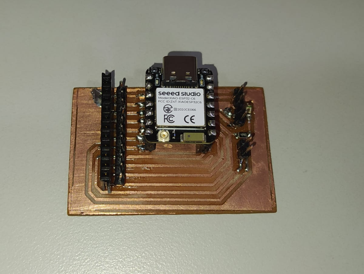
4. Board Used
For this assignment, I used the trainer PCB that I fabricated in the Electronics Production assignment. This board is based on the XIAO ESP32-C6 and gives easier access to the GPIO pins through male and female headers.
Using this board allowed me to connect the motor driver, the external 5 V power supply, and the indicator LED while keeping the microcontroller accessible for programming and testing.
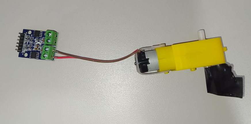
5. Output Device and Motor Driver
The output device selected for this assignment was a small yellow DC gear motor. This type of motor is useful for prototypes because the gearbox reduces speed and increases torque, making it suitable for moving small mechanisms such as the train in my final project.
To control the motor, I used an L9110S motor driver module. This module works as an H-bridge, which allows the microcontroller to control the direction of rotation of the DC motor by changing the polarity applied to the motor terminals.
5.1 DC Gear Motor Datasheet Reference
| Parameter | Typical value | Meaning for this assignment |
|---|---|---|
| Motor type | DC motor with gearbox | Provides rotational movement with reduced speed and increased torque |
| Operating voltage | 3 V to 6 V typical | The motor was powered using an external 5 V source |
| Control type | Polarity inversion | The rotation direction changes when the motor polarity is reversed |
| Current behavior | Higher current at startup or load | Requires a driver instead of direct GPIO connection |
| Application | Small mobile robots, mechanisms, toy vehicles | Useful for the Fab Train movement system |
5.2 L9110S Driver Datasheet Reference
| Parameter | Typical value | Meaning for this assignment |
|---|---|---|
| Driver type | Dual H-bridge motor driver | Allows control of DC motor direction |
| Logic input | Digital HIGH / LOW | The XIAO controls the driver using D0 and D1 |
| Motor supply | External supply recommended | The motor was powered from an external 5 V source |
| Function | Forward, reverse, stop | Used to rotate the motor in both directions |
| Protection role | Separates motor current from microcontroller pins | Prevents direct motor load on XIAO GPIO pins |
6. What is an H-Bridge?
An H-bridge is an electronic circuit that allows a DC motor to rotate in both directions. It works by changing the polarity applied to the two motor terminals. If one side of the motor receives positive voltage and the other side receives ground, the motor rotates in one direction. If the polarity is reversed, the motor rotates in the opposite direction.
The microcontroller should not drive the motor directly because GPIO pins are designed for logic signals, not for motor current. The driver receives the control signals from the XIAO and handles the higher current required by the motor.
| MOTOR_A1 | MOTOR_B1 | Motor behavior | LED behavior |
|---|---|---|---|
| HIGH | LOW | Motor rotates in direction 1 | LED ON |
| LOW | HIGH | Motor rotates in direction 2 | LED OFF |
| LOW | LOW | Motor stops | LED OFF |
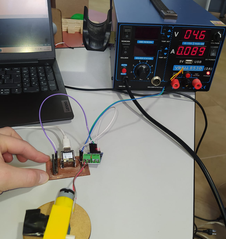
7. Circuit Assembly
The circuit was assembled using the XIAO ESP32-C6 trainer board, the L9110S motor driver, the yellow DC gear motor, an external 5 V power supply for the motor, and jumper wires.
The external 5 V supply was used only for the motor power side. It is very important that all grounds are connected together: the XIAO ground, the driver ground, and the external power supply ground. Without a common ground, the logic signals from the XIAO may not be interpreted correctly by the driver.
| Component | Function in the circuit |
|---|---|
| XIAO ESP32-C6 | Main microcontroller that sends digital control signals |
| Trainer PCB | Provides access to XIAO pins and includes the indicator LED |
| Red LED SMD 1206 | Indicator LED connected to D10 |
| DC gear motor | Output device that produces mechanical rotation |
| L9110S H-bridge module | Controls the direction of the DC motor |
| External 5 V power supply | Provides power to the motor side of the circuit |
| Jumpers | Used to connect the board, driver, motor, and power supply |
8. Control Logic
The motor is controlled with two digital output pins from the XIAO: D0 and D1. These pins are connected to the L9110S input pins. By changing the digital state of these two pins, the driver changes the motor direction.
The indicator LED is connected to D10. In this test, the LED turns on when the motor rotates in one direction and turns off when the motor changes direction. This provides a simple visual indication of the current output state.
A short delay of 50 ms is included before reversing the motor direction. This pause allows the motor driver to stop the previous state before changing polarity. Even if the pause is not very visible to the eye, it helps reduce abrupt switching and protects the circuit from unnecessary electrical stress.
9. Arduino Code
The Arduino code defines two motor control pins and one LED indicator pin. The program alternates the motor direction every second and uses a short stop delay before changing direction.
const int MOTOR_A1 = D0;
const int MOTOR_B1 = D1;

const int LED_INDICADOR = D10;

const unsigned long TIEMPO_GIRO = 1000;  // 1 second
const unsigned long TIEMPO_CAMBIO = 50;  // safe pause before reversing

void motorSentido1() {
  digitalWrite(MOTOR_A1, HIGH);
  digitalWrite(MOTOR_B1, LOW);

  digitalWrite(LED_INDICADOR, HIGH);
}

void motorSentido2() {
  digitalWrite(MOTOR_A1, LOW);
  digitalWrite(MOTOR_B1, HIGH);

  digitalWrite(LED_INDICADOR, LOW);
}

void motorParar() {
  digitalWrite(MOTOR_A1, LOW);
  digitalWrite(MOTOR_B1, LOW);

  digitalWrite(LED_INDICADOR, LOW);
}

void setup() {
  Serial.begin(115200);
  delay(3000);

  pinMode(MOTOR_A1, OUTPUT);
  pinMode(MOTOR_B1, OUTPUT);
  pinMode(LED_INDICADOR, OUTPUT);

  motorParar();

  Serial.println();
  Serial.println("================================");
  Serial.println("Prueba inversion de giro + LED");
  Serial.println("XIAO ESP32-C6 + L9110S");
  Serial.println("Motor A1 -> D0");
  Serial.println("Motor B1 -> D1");
  Serial.println("LED indicador -> D10");
  Serial.println("================================");
}

void loop() {
  Serial.println("Motor girando en sentido 1 | LED ENCENDIDO");
  motorSentido1();
  delay(TIEMPO_GIRO);

  Serial.println("Pausa antes de invertir | LED APAGADO");
  motorParar();
  delay(TIEMPO_CAMBIO);

  Serial.println("Motor girando en sentido 2 | LED APAGADO");
  motorSentido2();
  delay(TIEMPO_GIRO);

  Serial.println("Pausa antes de invertir | LED APAGADO");
  motorParar();
  delay(TIEMPO_CAMBIO);
}10. Functional Test
The functional test shows the DC motor rotating in one direction, stopping briefly, and then rotating in the opposite direction. The onboard red LED turns on when the motor rotates in the first direction and turns off when the motor changes direction.
This demonstrates that the XIAO ESP32-C6 is correctly controlling an external output device through the L9110S H-bridge driver.
11. Power and Electrical Considerations
Motors are output devices that can consume significantly more current than LEDs or simple logic components. For that reason, the motor was not powered directly from a GPIO pin or only from the microcontroller logic side. Instead, an external 5 V source was used for the motor supply.
A DC motor can generate current peaks during startup or when changing direction. These peaks can cause voltage drops, noise, or even resets in the microcontroller if the power system is not designed correctly. Using a motor driver helps separate the motor current from the logic pins.
For future PCB design, it is important to consider current consumption when defining trace width, connector type, and cable thickness. Small signals can use thinner traces, but motor power lines may require wider traces or thicker wires.
In some motor circuits, adding ceramic capacitors such as 103 capacitors can help reduce electrical noise and current spikes. This depends on the motor, the driver, and the stability of the power supply.
| Electrical point | Why it matters |
|---|---|
| Common GND | The XIAO, driver, and external power supply must share ground so the logic signals are referenced correctly. |
| External 5 V supply | The motor requires more current than a GPIO pin can provide safely. |
| Motor driver | The L9110S handles motor current and polarity inversion. |
| Current spikes | Startup and direction changes can produce current peaks that may affect the circuit. |
| Trace and wire size | Power lines must be designed according to the expected current. |
12. Problems and Fixes
- A motor should not be connected directly to a microcontroller pin because it can draw more current than the pin can safely provide.
- The circuit requires a common ground between the XIAO, the motor driver, and the external 5 V power supply. Without a common ground, the driver may not correctly read the control signals.
- The motor direction change needs a small pause to avoid abrupt polarity inversion. This was solved by adding a 50 ms stop delay before reversing.
- Motor circuits can introduce noise or current peaks. For future versions, additional capacitors and a more robust power distribution design can be added.
13. Reflection
- This assignment helped me understand the difference between reading inputs and controlling outputs. Output devices require the microcontroller to affect the physical world, often using more power than logic signals.
- I learned that motors should not be connected directly to microcontroller pins because their current demand is higher than what a GPIO can safely provide.
- Using the L9110S driver was important because it allowed the XIAO to control the motor direction without carrying the motor current directly.
- The common ground connection is essential. The external 5 V supply, the motor driver, and the XIAO must share GND so the control signals work correctly.
- The external 5 V source was necessary because the motor can generate current peaks, especially when starting or changing direction.
- I learned that motors can create electrical noise, parasitic currents, and voltage drops that may reset a microcontroller if the circuit is not designed properly.
- The short delay before reversing direction is a useful protection strategy because it prevents an immediate polarity inversion and gives the driver time to stop the previous state.
- The group assignment was useful because measuring voltage and current is necessary to understand the real power consumption of output devices.
- Understanding current consumption is important for choosing wire thickness, connector type, power supply capacity, and PCB trace width.
- Output devices such as motors and LEDs are essential for practical embedded systems because they create visible or mechanical actions from programmed logic.
- This test connects directly with my final project because the Fab Train needs a DC motor to move and may require additional actuators for the station.
- Overall, this week helped me understand how to safely control an output device using a microcontroller, external power, and a proper driver stage.