Week 19
Invention, Intellectual Property and Income
Dissemination plan, intellectual property strategy, future opportunities, project progress, and AI image prompt documentation for Fab Train.
1. Checklist
- ✅ Created a dissemination plan for my final project
- ✅ Outlined future possibilities and described how to make them probable
- ✅ Identified what tasks have been completed and what tasks remain
- ✅ Explained what is working and what is not working yet
- ✅ Defined the main questions that still need to be resolved
- ✅ Planned what will happen and when during the final development stage
- ✅ Reflected on what I learned during the development of the project
- ✅ Connected the final project with the Fab Academy assignments used during the process
- ✅ Defined the intellectual property approach for the project
- ✅ Explicitly defined and justified the selected license for Fab Train
- ✅ Explained the difference between GitLab as a repository and the license as a usage agreement
- ✅ Described possible income and sustainability opportunities
- ✅ Expanded the business model with target users, value proposition and possible revenue streams
- ✅ Included the prompt used to generate the AI concept image
- ✅ Identified the source of the AI-generated image
2. Final Project Overview
My final project is called Fab Train. It is a modular interactive train system for STEM learning. The project was born from the idea of creating a physical train circuit with wooden rails, a 3D printed train, embedded electronics, sensors, actuators, wireless communication, and a dashboard to visualize the system status.
The main goal is to build a demonstrative educational kit where a train moves through a rail circuit, interacts with a station, and sends information to a dashboard. The project combines digital fabrication, electronics, programming, communication, and interface design.
The system is designed as an open educational and interactive platform for children, makers, Fab Labs, and STEM learning environments. Although the current version is demonstrative, the project can be improved in the future as a learning kit or as a base for other IoT applications.
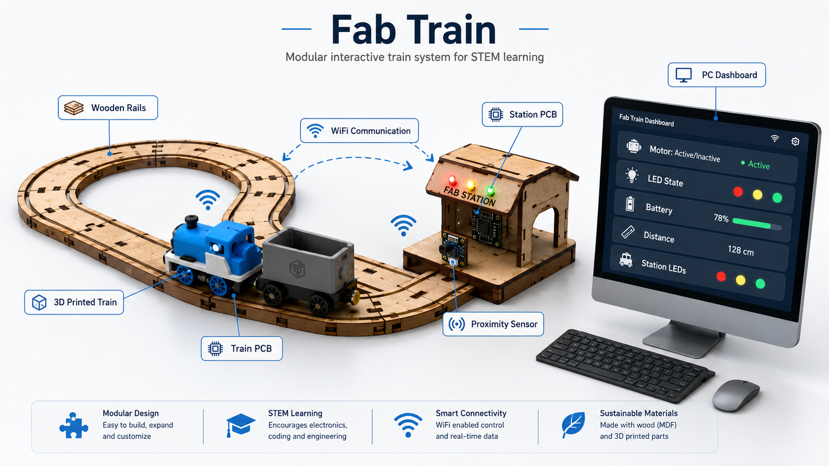
Image source: The image w19_1.png was generated
with an AI image generation tool to communicate the general concept of the
final project before the complete physical integration is finished.
3. AI Image Generation Prompt
The image w19_1.png was generated using the following prompt:
Create a clean, professional concept infographic image for a Fab Academy
final project called “Fab Train”. The image should visually explain the
complete concept of the project in a polished horizontal composition suitable
for a website hero image or project documentation page. Use a modern
isometric or semi-isometric illustration style on a light, clean background.
The overall look should be professional, educational, high-impact, and easy
to understand. Place a modular wooden train rail circuit in the center of
the image. The rails should look like CNC-machined MDF pieces, with straight
and curved modular sections connected together. On the rails, show one small
3D-printed locomotive and one wagon. The train should look like a prototype
made for digital fabrication, with a compact body, visible wheels, and a
small internal electronics area. Next to the track, include a small train
station structure made from digitally fabricated parts. The station should
include a proximity sensor facing the train and a few LED indicators.
Represent a station PCB inside or beside the station. Add simple Wi-Fi
icons and subtle dashed arrows between the train, the station, and a
computer dashboard. The communication should look clear but not cluttered.
The image should communicate that the train and station interact wirelessly.
On the right side, include a desktop computer or monitor showing a dashboard
interface. The dashboard should display the following labeled data clearly:
Motor: Active / Inactive, LED State, Battery, Distance, and Station LEDs.
Add elegant callout labels around the system with thin connector lines.
Include exactly these labels: Wooden Rails, 3D Printed Train, Train PCB,
Station PCB, WiFi Communication, and PC Dashboard. At the top, include the
title “Fab Train”. Under the title, include the subtitle “Modular interactive
train system for STEM learning”. Use a clean blue, white, gray, and natural
wood color palette. The visual style should feel like an engineering, STEM,
and Fab Lab project overview. Avoid clutter, avoid excessive decoration,
and keep all text readable. The final image should look like a refined
project concept graphic, not a casual collage. Use a horizontal 16:9 format.
The central focus should be the physical system: wooden rails, train, and
station. The dashboard should be visible on the right. The callouts should
support the explanation without covering important elements. Do not include
people. Do not include unrelated logos. Do not include extra text beyond
the title, subtitle, dashboard labels, and callout labels.
The rest of the images used in this assignment are intended to be screenshots or photographs from my own design, fabrication, electronics, testing, and documentation process.
4. How the Idea Evolved
The first idea of the project was to create a train that could move on a circuit made with digitally fabricated rails. From the beginning, I wanted the project to include a mechanical structure, electronics inside the train, and a way to monitor what was happening in the system.
During Fab Academy, the idea became more complete. The rail system was designed in 2D, the train was developed in 3D, the control PCB was designed and fabricated, and the electronic behavior was tested with motors, LEDs, and analog readings. Later, the project expanded to include a train station with a distance sensor, communication between two XIAO ESP32-C6 boards, and a dashboard running on a PC.
The final direction of the project is not only to create a moving train, but to create a small interactive system that can demonstrate how digital fabrication and IoT can be used for STEM education.
5. Connection with Fab Academy Assignments
Fab Train integrates many of the skills developed during the Fab Academy assignments. Each assignment contributed to a different part of the final project, from the original idea to the physical fabrication and the future integrated system.
| Assignment | How it contributed to Fab Train | Status in the final project |
|---|---|---|
| Week 1 - Project Management | Defined the first idea of the final project and documented the initial direction of the train system. | Used to explain the origin and evolution of the project. |
| Week 2 - Computer-Aided Design | Used 2D and 3D design tools to develop the rail geometry, train components, station concept and future packaging design. | Used for rails, train design, station design, and packaging. |
| Week 3 - Computer-Controlled Cutting | Used laser cutting knowledge for the future packaging made from 3 mm MDF and adhesive vinyl. | Still pending for the final packaging. |
| Week 4 - Embedded Programming | Used programming knowledge to test motor control, LED behavior, and analog voltage reading. | Used for the train control logic. |
| Week 5 - 3D Scanning and Printing | Used 3D printing to prototype the locomotive, wheels, and wagon. | Used for the physical train prototype and final corrections. |
| Week 6 - Electronics Design | Used EasyEDA to design the PCB that controls the train. | Used for the internal train electronics. |
| Week 7 - Computer-Controlled Machining | Used CNC machining to fabricate the MDF rail system. | Used for the main wooden rail circuit. |
| Week 8 - Electronics Production | Used CNC machining and fiber laser tests to fabricate PCB options, then soldered SMD and through-hole components. | Used for the train PCB fabrication and assembly. |
| Week 9 - Input Devices | Tested the Sharp 2Y0A21 F 3Z distance sensor and verified its useful detection range. | Used as a reference for the future station design. |
| Week 10 - Output Devices | Tested the DC motor and LEDs as output devices controlled by the microcontroller. | Used for train movement and visual feedback. |
| Week 11 - Networking and Communications | Will be used for WiFi communication between the train and the station, both based on XIAO ESP32-C6 boards. | Pending integration in the final system. |
| Week 15 - Interface and Application Programming | Used dashboard and IoT interface concepts to visualize sensor and output states. | Will be used for the final PC dashboard. |
6. Rail Design
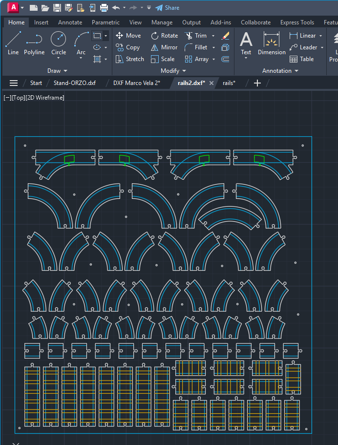
The first technical step was to design the train rails in 2D using AutoCAD. This process was connected with the computer-aided design assignment because I used vector design concepts, drawing precision, measurements, and digital modeling criteria.
I created different rail modules to make the system modular. The rail set includes short, medium, and long straight sections; curves of 30°, 45°, 60°, and 90°; curves for both left and right directions; and bifurcations where the train can continue straight or take a curved path.
During the design process, I considered the dimensions of the train wheels, the rail spacing, the machining strategy, and the amount of material needed. The objective was to make the rails functional while also optimizing the CNC fabrication process.
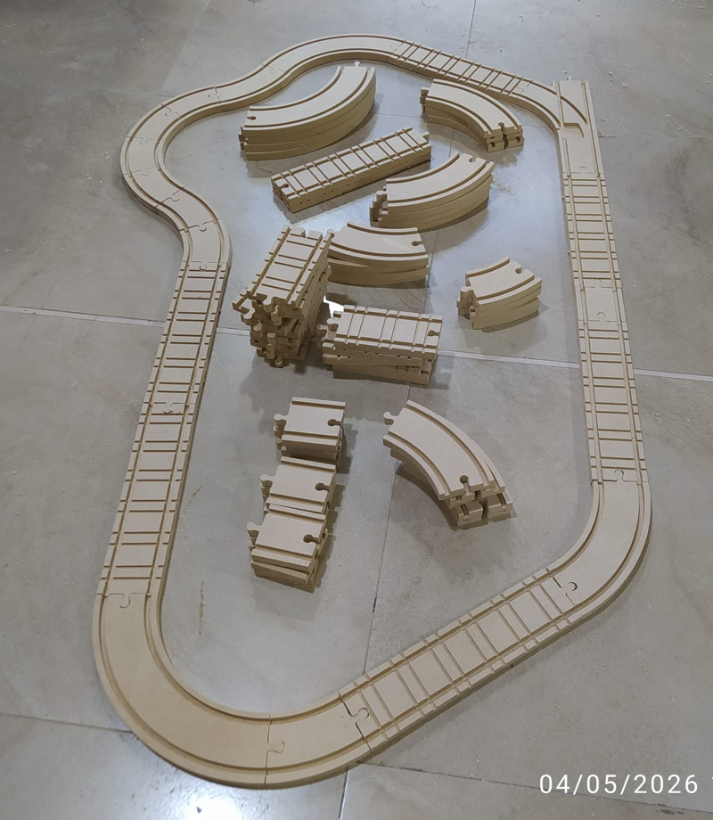
7. CNC Fabrication of the Rails
For the fabrication of the rails, I used a 12 mm MDF board. The machining setup was prepared in Aspire Vectric, where I configured the toolpaths, cutting depths, and machining order.
The channel where the train wheels pass was machined with a 6 mm end mill using a profile strategy with a depth of approximately 6 mm over the rail line. Then, I used a 3 mm two-flute upcut end mill to make rail details. Finally, the same 3 mm tool was used to cut the external profile of each rail piece through the complete thickness of the MDF.
Because of the number of rail pieces and the detail level required, the complete CNC machining process took approximately 5 hours. After machining, I removed the parts from the board and sanded the surface and edges to improve the finish and remove small imperfections.
8. Train Design and 3D Printing
The train was designed in 3D using Autodesk Inventor. The design includes one locomotive and one wagon. I also designed the wheels and tested their relationship with the rail geometry.
I printed several prototypes using a Bambu Lab X1E. These tests helped me review dimensions, wheel behavior, mechanical fit, available space for electronic components, and compatibility between the train body, the rails, and the PCB.
The current train is still being refined. I already have functional prototypes, and I am correcting dimensions to reach the final version of the locomotive and wagon.
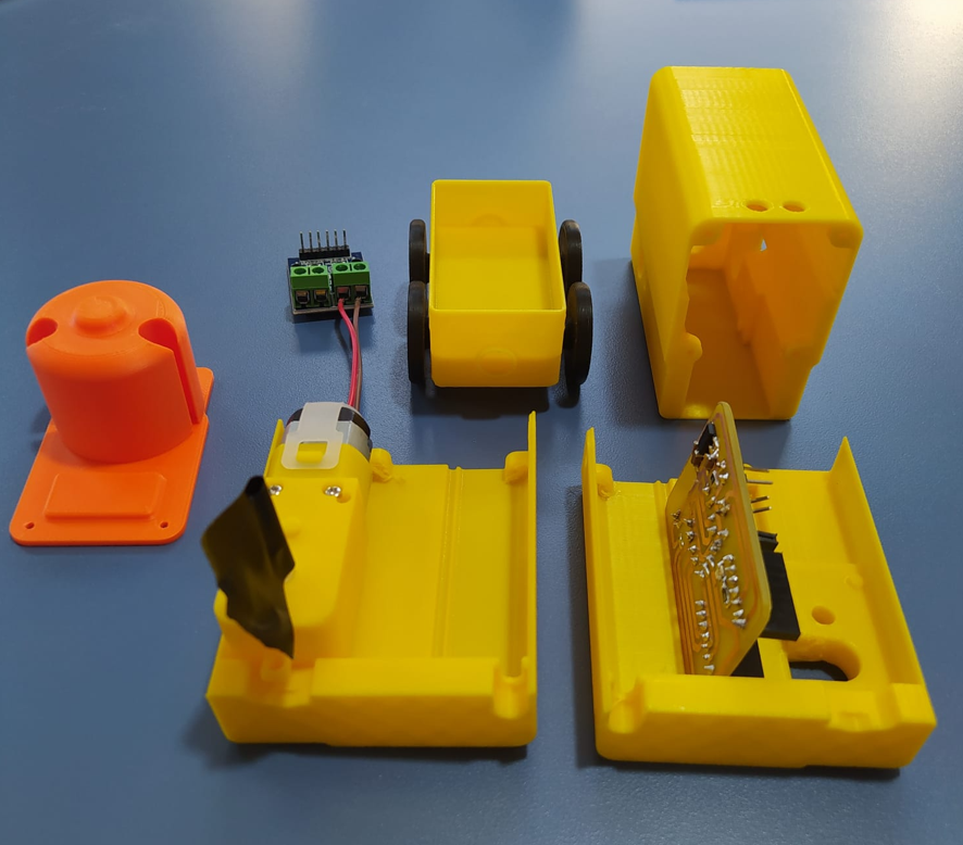
9. Train PCB and Electronics
The internal control PCB for the train was designed in EasyEDA. First, I created the schematic, and then I designed the PCB layout. The board was designed as a compact one-sided PCB, but it includes both SMD and through-hole components to optimize space and assembly.
The main controller is a XIAO ESP32-C6. The train is powered by an 8.4 V battery. Because the XIAO ESP32-C6 works with 3.3 V logic, I included a voltage regulator with input and output capacitors. I also added a voltage divider to read the battery voltage safely through an analog input.
The PCB also includes an L9110S H-bridge module for motor control, LEDs, resistors, and the necessary connections for the train outputs. The voltage divider is important because the battery voltage is higher than the safe voltage level of the microcontroller input.
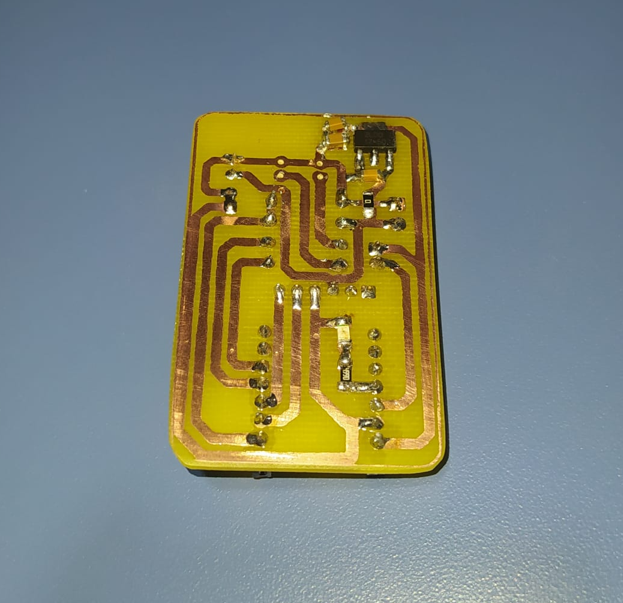
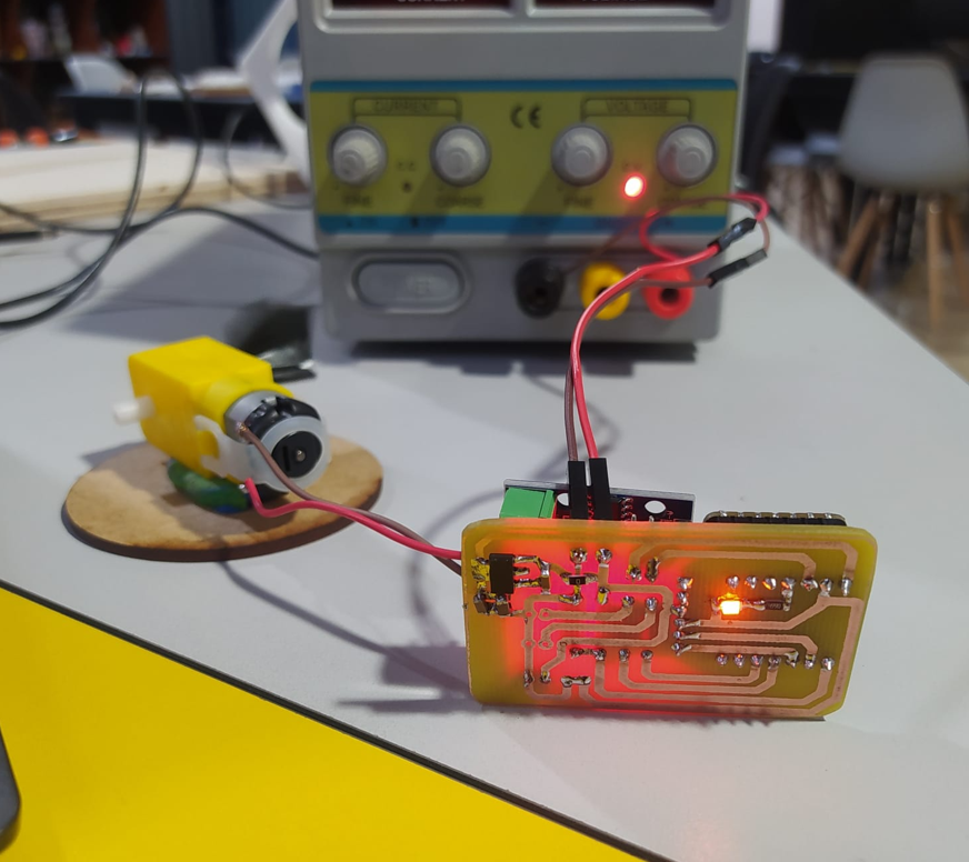
10. PCB Fabrication and Output Tests
The PCB fabrication process was connected with the electronics production assignment. I tested two fabrication alternatives: CNC machining and fiber laser fabrication. This allowed me to compare different processes and have more than one option for producing the board.
After fabrication, I soldered the components and tested the main outputs. The DC motor and LEDs were tested using the embedded programming and output devices knowledge developed in previous assignments.
The train PCB currently allows me to test the motor, LEDs, and battery voltage reading. This confirms that the basic electronic behavior of the train is working before integrating it with the station and the dashboard.
11. Final Integrated System
The final system will include the rail circuit, the 3D printed train, the train PCB, the station, the station PCB, WiFi communication, and a PC dashboard. The train will move through the rail circuit and interact with the station when it arrives.
The station will include another XIAO ESP32-C6, a Sharp 2Y0A21 F 3Z distance sensor, and LEDs. When the station detects the train, it will send a command through WiFi so the train stops for a defined time. During this interaction, the LED states will change, and then the train will continue moving.
The distance sensor has already been tested in a previous input devices assignment, and it worked in an approximate range from 10 cm to 80 cm. This is important because the physical design of the station must position the sensor at a distance where the train can be detected reliably.
The dashboard will run on a PC and will show the state of the train and the station. For the train, it will show whether the motor is active or inactive, the LED state, and the battery value. For the station, it will show the detected distance and the LED state.
12. Intellectual Property
Fab Train is planned as an open educational project. The documentation, design files, fabrication files, and source code will be shared through my Fab Academy website and my GitLab repository so that other students, makers, Fab Labs and educators can study, reproduce and adapt the project for learning purposes.
In my case, GitLab is the platform where the project files are hosted and shared. However, GitLab is not the license itself. GitLab is the place where the files are stored, while the license defines how other people are allowed to use, copy, modify, share, or adapt the project.
The selected license for Fab Train is Creative Commons Attribution-NonCommercial 4.0 International (CC BY-NC 4.0). This means that other people can share and adapt the documentation and project materials for non-commercial purposes, as long as they give appropriate credit to the author. Commercial use would require additional permission.
| License decision | Meaning for Fab Train | Justification |
|---|---|---|
| Attribution required | People can use or adapt the project, but they must credit the original author and documentation source. | This protects authorship recognition while still allowing the project to be shared as an educational reference. |
| Non-commercial use | The project can be used for learning, workshops, Fab Lab demonstrations and educational adaptation, but not for direct commercial sale without permission. | This is important because Fab Train has educational potential, and I want to avoid direct commercial exploitation of the files without an agreement. |
| Adaptation allowed | Other students, makers or educators can modify the rails, train, electronics, station, dashboard or documentation for their own non-commercial learning context. | The project is intended to be improved and reused as a STEM learning platform, not kept closed. |
| Open documentation | The process, images, files and code are documented publicly through Fab Academy and GitLab. | Open documentation supports reproducibility and helps other people understand the complete development process. |
I chose this license because Fab Train was created as an educational and digitally fabricated STEM project. The license supports sharing, study, adaptation and learning, while maintaining author recognition and limiting commercial use without permission.
13. License and File Sharing Strategy
The following table explains how each type of project material will be shared and what type of use is expected.
| Project material | Where it will be shared | Access / license approach | Allowed use |
|---|---|---|---|
| Documentation | Fab Academy website | Creative Commons Attribution-NonCommercial 4.0 International (CC BY-NC 4.0) | Read, study, cite, and share with attribution. |
| CAD files | GitLab repository | Open educational access | Download, modify, fabricate, and study for learning purposes. |
| Fabrication files | GitLab repository | Open educational access | Use as reference for CNC machining, laser cutting, 3D printing and PCB fabrication. |
| PCB files | GitLab repository | Open educational access | Study, fabricate, and adapt for non-commercial educational use. |
| Source code | GitLab repository | Open repository access | Study, modify, reuse, and learn from the code with attribution. |
| Photos and videos | Fab Academy website | Creative Commons Attribution-NonCommercial 4.0 International (CC BY-NC 4.0) | Share or reference with attribution. |
| AI-generated image | Fab Academy website | Documented as AI-generated visual material | Used as a concept visualization, with the prompt documented in this page. |
14. Dissemination Plan
The dissemination plan explains how I will share the project after finishing the final prototype. The main objective is to make Fab Train understandable, replicable, and useful for people interested in digital fabrication, electronics, programming, and STEM education.
| Channel | What will be shared | Purpose |
|---|---|---|
| Fab Academy website | Complete documentation, process, images, videos, design decisions, problems, and results. | To document the project as part of Fab Academy and make the process accessible. |
| GitLab repository | Source files, design files, fabrication files, and code. | To keep the project files organized and available for replication or future development. |
| Final presentation | Project summary, final system, video, slide, and explanation of the main achievements. | To communicate the project clearly during the final evaluation. |
| Final video and hero image | Visual demonstration of the system working as an integrated project. | To show the essence of the project in a short and clear format. |
| Fab Lab demonstration | Physical demonstration with rails, train, station, dashboard, and packaging. | To show the project to local students, makers, and possible users. |
| Step-by-step documentation | Design, fabrication, electronics, programming, integration, and future improvements. | To help other people understand how to build or adapt the project. |
I am not planning to create specific social media accounts for the project at this stage. The priority is to complete a strong Fab Academy documentation page, share the files through GitLab, and present the project in the final Fab Academy presentation.
15. Dissemination Timeline
The dissemination strategy is organized in stages so the project can be shared progressively during and after the final development process.
| Moment | Dissemination action | Expected result |
|---|---|---|
| During final development | Update the Fab Academy documentation continuously. | The process remains visible and traceable. |
| Before final presentation | Upload fabrication files, PCB files, code, images, diagrams and media to GitLab. | Other people can access and study the project files. |
| Final presentation | Present the final system, hero image, slide, and demonstration video. | The project is communicated clearly during evaluation. |
| After Fab Academy | Use Fab Train as a demonstrative STEM and IoT educational system. | The project can be reused in workshops or Fab Lab demonstrations. |
| Future development | Improve the dashboard, simplify assembly, increase reliability, and create learning activities. | The project can evolve into a stronger educational kit or interactive installation. |
16. Income and Sustainability
Fab Train is not planned as a closed commercial product in its first version. It is a demonstrative open source project that can be used as a base for future educational and interactive applications.
However, the project has potential to become scalable because it combines digital fabrication, electronics, IoT, and education. This creates several possible paths for sustainability and future income.
| Opportunity | Description | How to make it probable |
|---|---|---|
| STEM education kit | Fab Train can become a modular kit for teaching electronics, programming, sensors, actuators, and digital fabrication. | Create clear documentation, learning activities, assembly guides, and classroom examples. |
| Workshops | The project can be used in workshops for children, makers, students, or teachers. | Prepare short exercises, simplified versions, and guided activities around the train system. |
| Physical kits | The rails, train, station, PCB, and packaging could be prepared as a local fabrication kit. | Standardize the parts, reduce assembly complexity, and prepare a bill of materials. |
| Interactive installations | The system can be adapted for exhibitions, demonstrations, museums, or Fab Lab showcases. | Improve the visual design, robustness, and dashboard experience. |
| IoT applications | The same logic of sensing, communication, actuation, and dashboard visualization can be extended to other projects. | Make the electronics and software modular so they can be reused in other interactive systems. |
17. Income Strategy and Validation
Fab Train is planned as an open educational project, but open source projects can still create value through workshops, educational experiences, demonstrations, fabrication services, and modular improvements.
Instead of focusing on closing the project, the strategy is to use the documentation, design, and fabrication knowledge as a base for educational and interactive applications.
| Income path | Target user | Value offered | First validation step |
|---|---|---|---|
| STEM workshops | Schools, children, Fab Labs and makers | Hands-on learning through fabrication, electronics, programming and IoT. | Run a pilot workshop using the demonstrative prototype. |
| Educational kit | Teachers and students | A modular train system that can be assembled, programmed and modified. | Create assembly guides, simplified documentation and learning activities. |
| Fabrication kit | Local educational institutions | Ready-to-fabricate or ready-to-assemble train components. | Standardize files, create a BOM and reduce assembly complexity. |
| Interactive installation | Museums, events, laboratories and Fab Labs | Interactive demonstration of automation, sensing and IoT concepts. | Improve robustness, visual design and presentation quality. |
| Reusable IoT system | Makers and students | Reusable communication, sensing, actuation and dashboard logic. | Document WiFi communication and dashboard integration as reusable modules. |
18. Business Model Expansion
To make the income strategy more concrete, I expanded the business model by identifying the main target users, the value proposition for each group, and possible revenue streams. The first version of Fab Train remains an open educational prototype, but the project could become sustainable through services, workshops, kits and educational experiences.
Target Users and Value Proposition
| Target user | Need or problem | Value proposition |
|---|---|---|
| Schools and teachers | They need hands-on tools to explain STEM topics in a practical and engaging way. | Fab Train offers a physical kit that connects mechanics, electronics, programming, sensors and IoT through a familiar object: a train. |
| Fab Labs and makerspaces | They need demonstrative projects that show digital fabrication and system integration. | The project can be used as a workshop activity or demonstration to explain CNC machining, 3D printing, PCB fabrication, embedded systems and interface design. |
| Students and beginners | They need accessible examples that show how different technologies work together in one system. | Fab Train provides a modular learning platform where users can study movement, sensing, communication, dashboards and physical assembly. |
| Museums, events and exhibitions | They need interactive installations that are visual, educational and easy to understand. | Fab Train can become an interactive demonstration of automation and IoT, where visitors can see the system reacting in real time. |
| Local institutions or training centers | They may need customized educational material for workshops or short courses. | The project can be adapted into guided activities, fabricated locally and customized for different learning levels. |
Possible Revenue Streams
| Revenue stream | Description | Why it fits the license strategy |
|---|---|---|
| STEM workshops | Paid workshops where students build, program or test parts of the train system. | The documentation can remain open while the paid value comes from guidance, teaching, materials and facilitation. |
| Educational kit fabrication | Local fabrication of rails, train parts, station parts, PCBs and packaging for schools or labs. | Commercial fabrication or sale would require permission or a specific agreement, while educational replication remains open. |
| Training and consulting | Support for teachers, labs or institutions that want to adapt the project for their own classes. | The files can be studied openly, but the service is based on technical support, adaptation and implementation. |
| Interactive exhibitions | Rental, installation or demonstration of a robust version of Fab Train for events, museums or maker fairs. | The project can be presented publicly while the income comes from the event service and the prepared demonstrator. |
| Advanced modules | Future expansion modules such as additional stations, sensors, track layouts, dashboard functions or classroom activities. | The base project can stay open while additional services or custom improvements can generate sustainability. |
This business model keeps the educational spirit of the project while making future sustainability possible. Instead of closing the project files, the strategy is to create value through learning experiences, fabrication, implementation support, custom adaptations and improved versions for real users.
19. What Is Working
- The modular rail system has been designed in 2D using AutoCAD.
- The rail pieces have been fabricated in 12 mm MDF using CNC machining.
- The rails were sanded and finished after machining.
- The locomotive, wheels, and wagon have been designed in 3D using Autodesk Inventor.
- Several train prototypes have been printed using the Bambu Lab X1E.
- The train PCB has been designed in EasyEDA.
- The train PCB has been fabricated using different production tests.
- The components of the train PCB have been soldered.
- The DC motor has been tested as an output device.
- The LEDs have been tested as visual output indicators.
- The battery voltage reading has been considered with a voltage divider.
- The Sharp distance sensor was previously tested and worked in an approximate range from 10 cm to 80 cm.
20. What Is Not Working Yet
The complete integrated system is not finished yet. Some parts are still pending because they depend on the final station design, the station PCB, the wireless communication, and the dashboard integration.
- The final station structure still needs to be designed and fabricated.
- The station PCB still needs to be designed, fabricated, soldered, and programmed.
- The Sharp sensor has not yet been integrated into the final station PCB.
- The WiFi communication between the train and the station still needs to be implemented and tested.
- The dashboard still needs to be completed on the PC.
- The system still needs full integration between rails, train, station, electronics, communication, and dashboard.
- The packaging still needs to be designed, laser cut, assembled, and finished with adhesive vinyl.
- The final video and hero image still need to be produced after the integrated system is working.
21. Remaining Tasks
| Task | Related assignment | Description |
|---|---|---|
| Design the station structure | Week 2 and Week 7 | Create the 2D design of the station pieces and fabricate them using CNC machining. |
| Design and fabricate the station PCB | Week 6 and Week 8 | Create the schematic and PCB for the station with XIAO ESP32-C6, Sharp sensor, and LEDs. |
| Program the station | Week 4 and Week 9 | Read the Sharp sensor distance and control the LED states. |
| Program train-station communication | Week 11 | Use WiFi communication between the two XIAO ESP32-C6 boards so the station can command the train to stop and continue. |
| Create the PC dashboard | Week 15 | Visualize train motor state, train LED state, battery value, station distance, and station LED state. |
| Integrate the full system | Final project | Test the rails, train, station, electronics, communication, dashboard, and physical behavior together. |
| Design and fabricate packaging | Week 2 and Week 3 | Design the packaging in AutoCAD and Illustrator, cut it in 3 mm MDF using RDWorks, and apply adhesive vinyl. |
| Prepare final documentation | Project management | Complete the Fab Academy pages, add images, add files, create the final video, and prepare the final slide. |
22. Questions to Resolve
- What is the best physical position for the Sharp sensor inside the station?
- What distance threshold should be used to detect the train reliably?
- How stable will the WiFi communication be between the two XIAO ESP32-C6 boards?
- How long should the train stop at the station before continuing?
- How should the LEDs communicate the state of the train and the station to the user?
- How fast should the dashboard update without affecting the performance of the system?
- How much autonomy will the 8.4 V battery provide during a complete demonstration?
- Will the train move smoothly after several laps on the rail circuit?
- What mechanical adjustments are still needed in the wheels, locomotive body, or rail joints?
- How can the system be simplified in the future to make it easier for children or beginners to assemble?
23. Final Development Schedule
To complete the final project, I organized the remaining work into an 8-day plan. The plan focuses first on the missing technical elements, then on integration, packaging, documentation, video, and final presentation materials.
| Day | Main activities | Expected result |
|---|---|---|
| Day 1 | Design the station in 2D by pieces, design the station PCB, and fabricate both parts. | Station structure and PCB ready for assembly. |
| Day 2 | Program the station, program the train communication logic, and start the dashboard. | Basic communication and interface structure working. |
| Day 3 | Continue dashboard development, run tests, correct possible failures, and improve the code. | Dashboard showing train and station states. |
| Day 4 | Integrate the rail circuit, train, station, electronics, and communication. | First complete integrated system test. |
| Day 5 | Verify full functionality, correct mechanical or electronic problems, and improve reliability. | Stable system for final demonstration. |
| Day 6 | Design and fabricate the packaging using 3 mm MDF, laser cutting, RDWorks, and adhesive vinyl. | Packaging completed. |
| Day 7 | Document the last assignments, take final photos, and start preparing the final video. | Documentation and visual material advanced. |
| Day 8 | Finish documentation, final video, hero image, final slide, and general project review. | Final project ready for presentation. |
24. Project Essence
Fab Train is a project that connects the physical and digital worlds through an educational train system. The physical part includes the MDF rail circuit, the 3D printed train, the station, and the packaging. The digital and electronic part includes the PCBs, motor control, LEDs, analog sensing, WiFi communication, and dashboard visualization.
The essence of the project is to demonstrate how a simple and familiar object, such as a train, can become an educational platform for learning digital fabrication, electronics, programming, sensors, actuators, and IoT.
The first version is not intended to be a final commercial product. It is a demonstrator and a prototype that can evolve into a STEM kit, a workshop activity, or an interactive installation.
25. Assignment Summary
This assignment helped me organize the final stage of Fab Train from three perspectives: how the project will be shared, how the intellectual property will be handled, and how the project could continue after Fab Academy.
The dissemination plan is based on open documentation through my Fab Academy page and GitLab repository. The project files, code, images, design decisions and process documentation will be shared so that other students, makers and educators can study and replicate the work.
The future development path is focused on education. Fab Train can become a STEM kit, a workshop activity, a local fabrication kit, an interactive installation or a reusable IoT learning platform. To make these opportunities realistic, the next steps are to improve reliability, simplify assembly, document the system clearly, create learning activities and test the project with real users.
The business model was expanded by defining target users, value propositions and possible revenue streams. This helped me understand that Fab Train can remain open for educational use while still creating future value through workshops, fabrication services, training, interactive demonstrations and customized learning modules.
At this stage, several tasks are already completed: the rail system was designed and machined, the train was designed and prototyped, the train PCB was designed and fabricated, and the main outputs were tested. The remaining work is focused on the station, station PCB, WiFi communication, dashboard, packaging, final integration, video and hero image.
The current working parts are the individual subsystems: rails, train prototypes, PCB fabrication, motor tests, LED tests and battery voltage reading strategy. The complete system is not fully integrated yet because the station, communication, dashboard and packaging still need to be finished.
The main unresolved questions are related to the sensor position, distance threshold, WiFi communication stability, train stop time, LED state logic, dashboard update rate, battery autonomy and mechanical reliability after several laps on the track.
The final development was organized into an 8-day schedule that prioritizes the station, PCB fabrication, programming, dashboard development, full system integration, packaging, final documentation, video and final project review.
Through this assignment, I learned that completing a final project is not only about building the prototype. It also requires planning how it will be shared, deciding how people can use the files, documenting AI-generated content transparently, identifying future opportunities and defining a clear path to finish the remaining work.
26. Reflection
- This project helped me understand how a final project can grow from a simple idea into an integrated system with mechanical, electronic, and digital components.
- I learned that documenting the evolution of the idea is important because the final result is built from many small decisions made during the course.
- Designing the rail system taught me to think about geometry, modularity, tolerances, and the relationship between design and fabrication.
- CNC machining the rails showed me that toolpath planning, tool selection, cutting depth, and machining time directly affect the final quality of the parts.
- The 3D printed train prototypes helped me understand that a digital model usually needs several physical tests before reaching a reliable version.
- Designing the PCB for the train helped me connect electronics design with the physical limits of the object where the board must be installed.
- I learned that voltage levels are critical in embedded systems. The XIAO ESP32-C6 works with 3.3 V logic, so the 8.4 V battery and analog readings required careful protection and voltage division.
- Testing the motor and LEDs separately made the integration easier because I could verify each output before combining it with the complete system.
- The Sharp distance sensor test was useful even before building the station, because it gave me a reference range that affects the physical design.
- I understood that IoT is not only about sending data to a dashboard. It also requires reliable sensing, correct communication, clear states, and useful feedback for the user.
- The dashboard will help make the system easier to understand because the user can see the motor state, LED state, battery level, distance, and station status in one place.
- Planning the dissemination strategy helped me see the project not only as a prototype, but also as a resource that other people can study, replicate, and improve.
- Thinking about intellectual property helped me understand the difference between sharing files on GitLab and defining how other people are allowed to use those files.
- Documenting the AI image prompt helped me understand that AI-generated media must also be transparent and traceable in the project documentation.
- The project has educational potential because it can be used to explain fabrication, circuits, programming, communication, and interfaces through a tangible object.
- I learned that future income does not necessarily mean closing the project. An open project can still create value through workshops, kits, training, demonstrations, and custom adaptations.
- The remaining integration stage is one of the most important parts because every subsystem must work together: rails, train, PCB, station, sensor, communication, dashboard, and packaging.
- This assignment helped me organize the final stretch of the project by separating what is already working, what is missing, and what questions still need to be answered.
- Overall, Fab Train helped me connect many Fab Academy assignments into one coherent project with a clear educational purpose.