Final Project - Zakkerni
Manufacturing
In this section, I will discuss the manufacturing process of the final project, including the materials used, the fabrication techniques employed, and any challenges faced during production. The goal is to ensure that the final product is durable, functional, and meets the design specifications outlined in the previous sections.
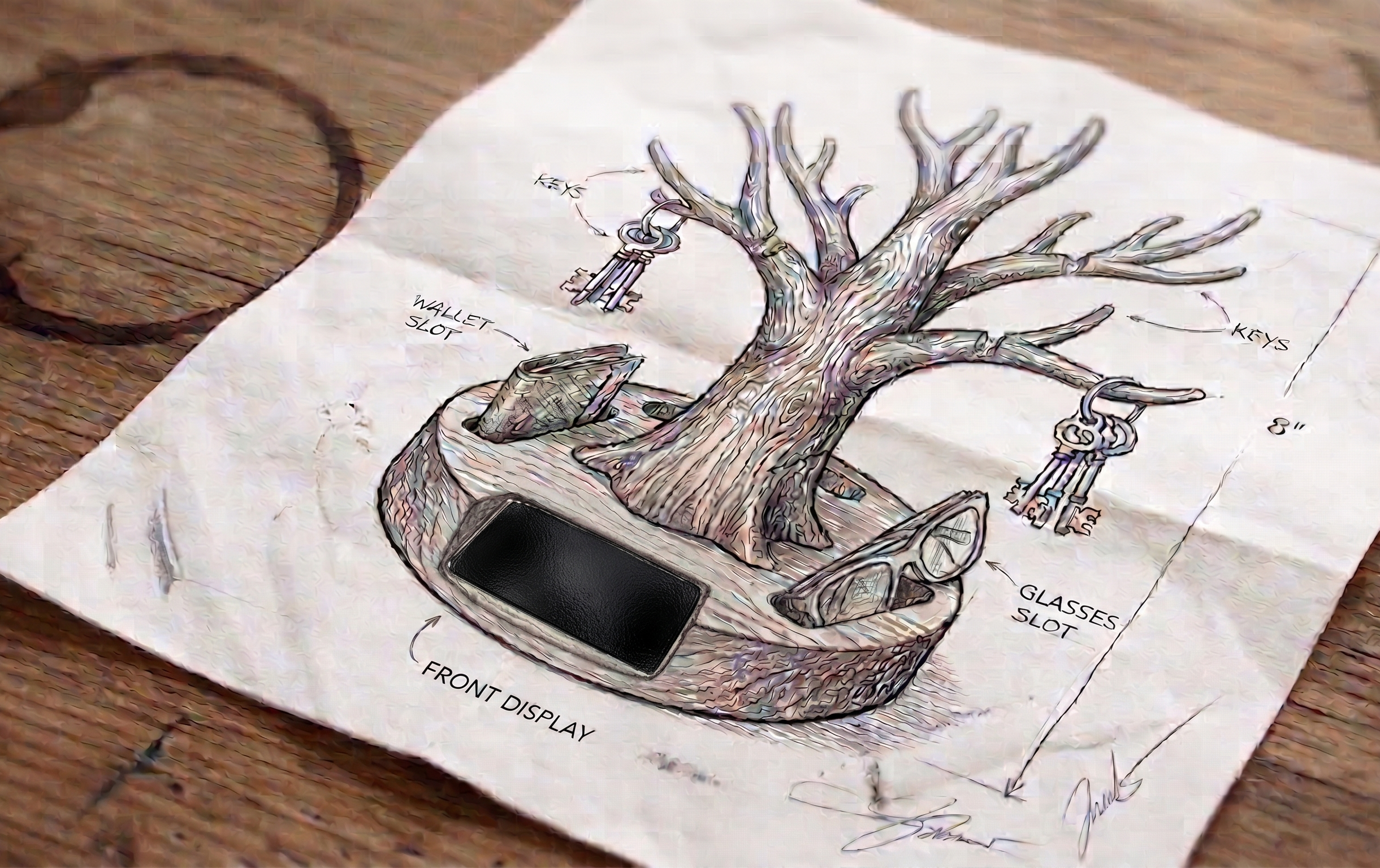
The manufacturing process will involve several steps, including:
- CNC machining of the main body
- 3D printing of the slot, hooks, backside, and OLED screen holder
- Laser cutting of the bottom part
- PCB fabrication
Here is Fusion file that contains all the designs for the project: Final Project Fusion
Manufacturing Process
3D Printing
The 3D printing process was used to create the slot, hooks, backside, and OLED screen holder. The materials used for 3D printing were PLA, Woodfill, and XT.
Slots
Here is the stl file: Slots STL
The slots were printed using PLA material on Prusa printer. The slots were designed to hold the ultrasonic sensors and IR sensor securely in place.
hooks
Here is the STL file: hooks STL
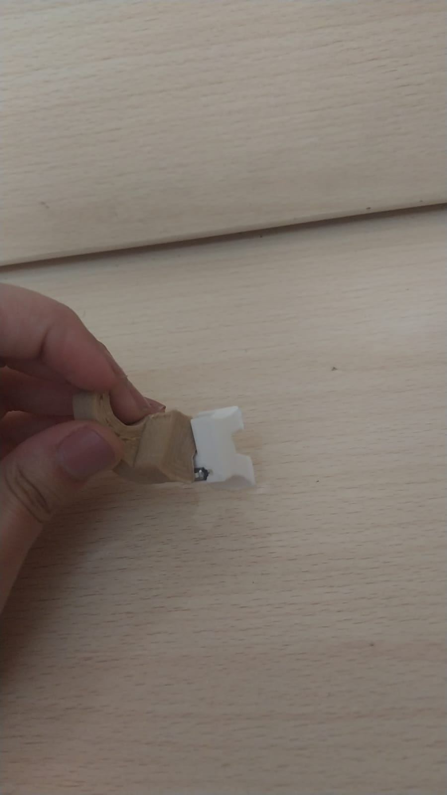
The hooks were built from two parts:
hooks - first part
This part was printed using Woodfill to achieve a wood-like appearance and natural feel. It was printed on an Ultimaker S5 printer.
hooks - second part
This part was printed using PLA on an Ultimaker S5 printer. It holds the pushbutton and ensures it stays in place.
Here is the final hooks:
Backside
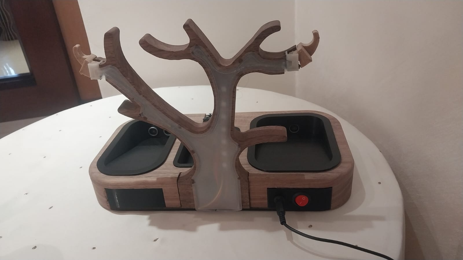
The backside of the tree was printed using XT material on a Prusa printer.
Here is the final backside:
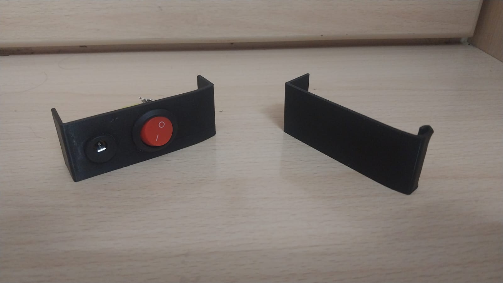
Also, on the back side I printed small parts to hold the on/off switch and the power socket:
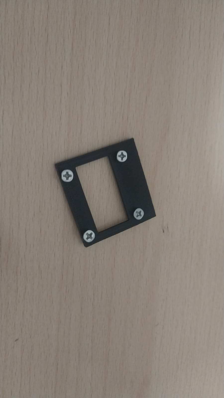
OLED Screen Holder
Here is the stl file: OLED Holder STL
The OLED screen holder was printed using PLA material on Ultimaker s5 printer. The holder was designed to securely hold the OLED screen in place and provide easy access for wiring and maintenance.
Prototype base & tree
Here is the STL file: Prototype Base & Tree STL
The prototype base and tree were printed using PLA on an Ultimaker S5 printer before I cut them on a CNC. Woodworking is expensive, and I wanted to make sure the design was correct and the parts fit together properly. The prototype was used to test the assembly process and ensure that all components fit together as intended.
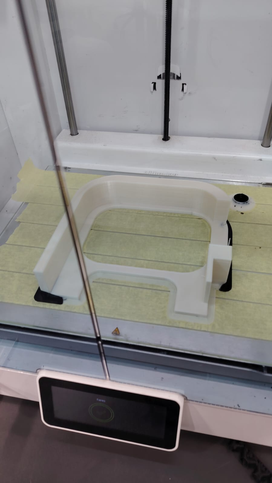
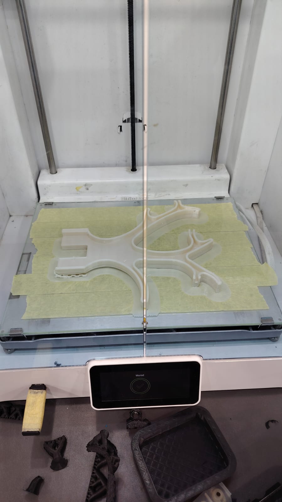
Here is the final result after joining them together:
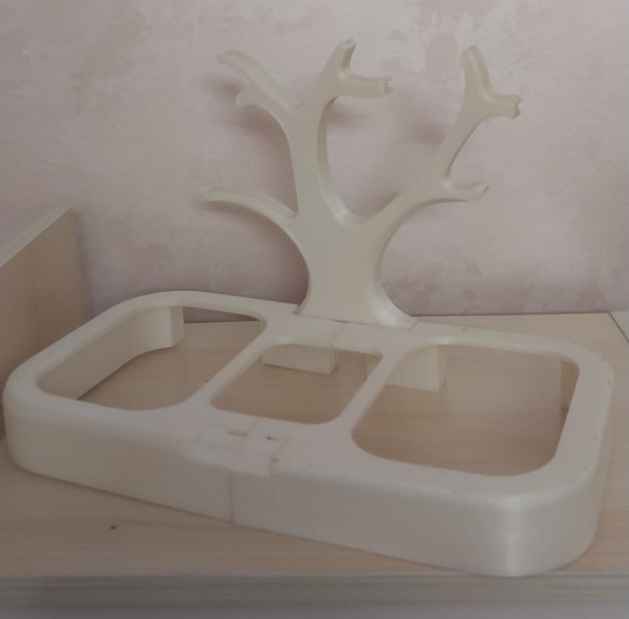
After I confirmed the design and that the parts fit together properly, I could now tell that the design was ready to be cut on the CNC.
CNC Machining
The main body of the project was fabricated using CNC machining. The material used for CNC machining was Walnut wood using shopbot
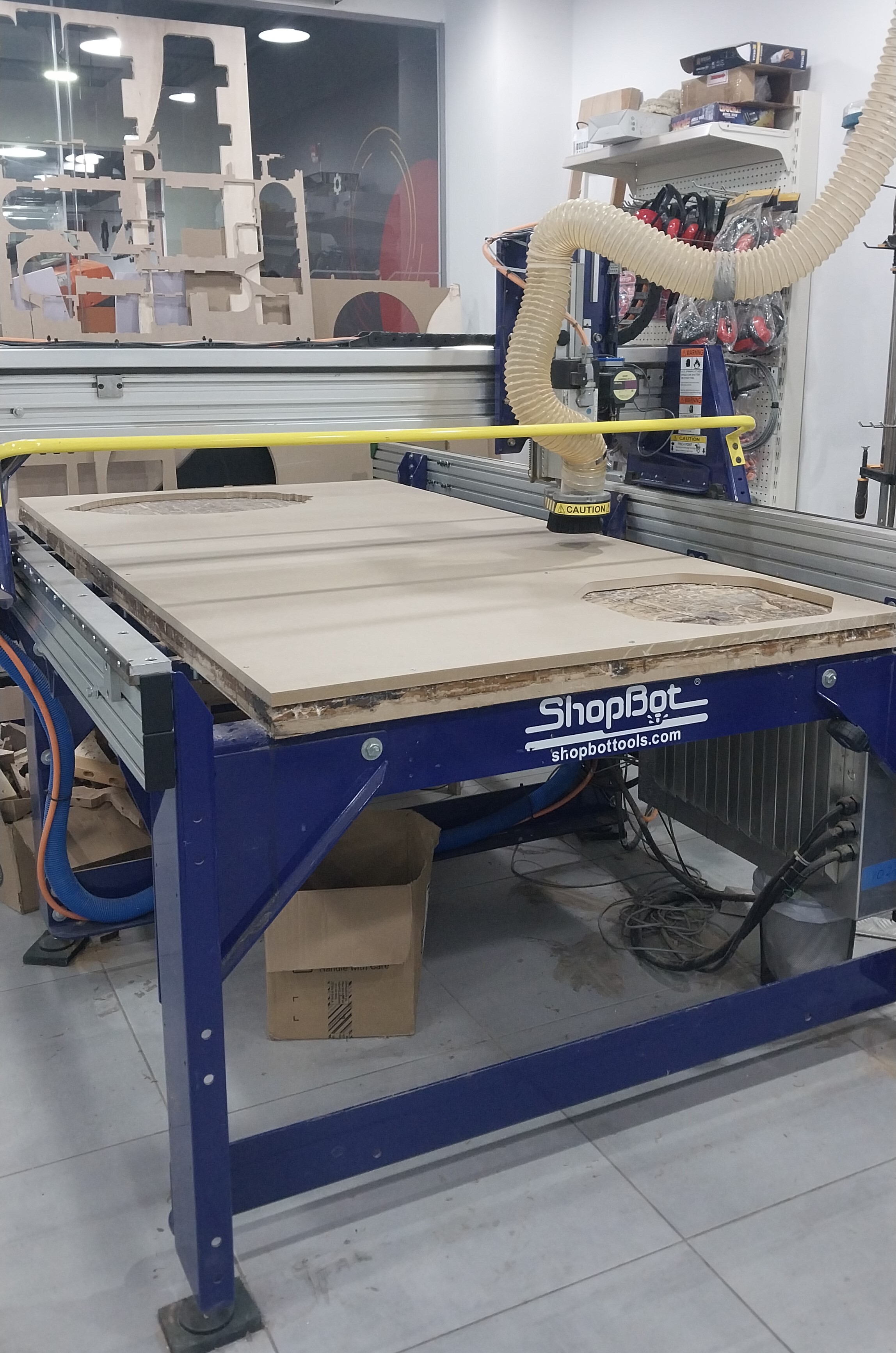
Here is the part to be machined:
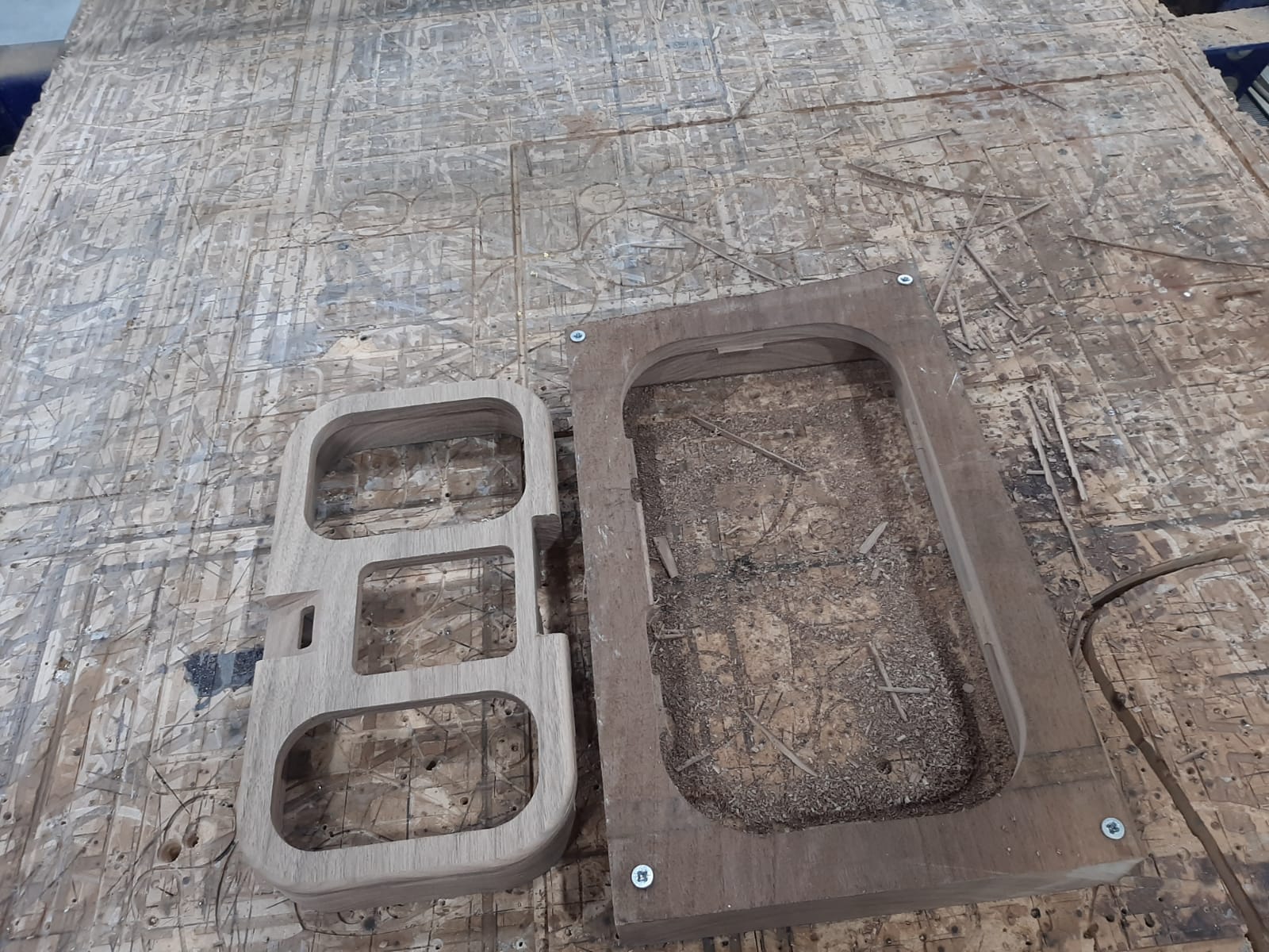
To cut the parts, I had to machine the piece on both sides because some features needed to be cut on both faces.
Here is the Fusion 360 file that contains the cutting paths: CNC Fusion File
Here is the final result after cutting the part on the CNC:
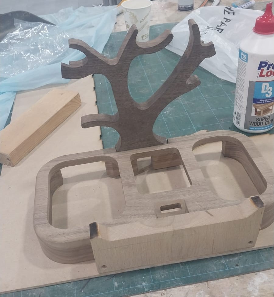
I also cut the tree on the CNC, here is the final result:
Laser Cutting
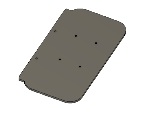
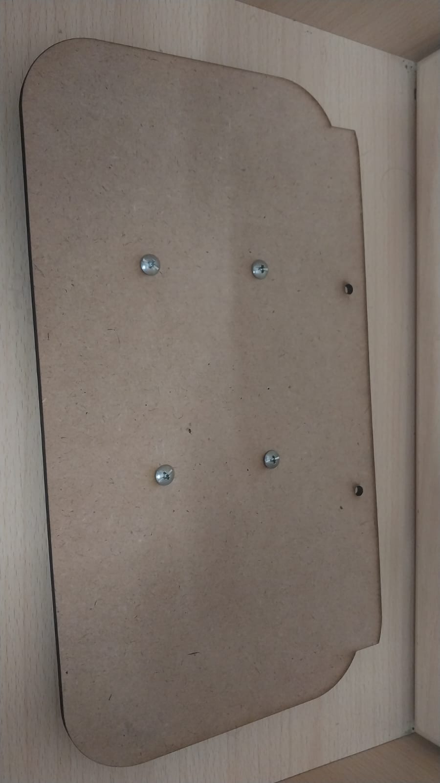
The bottom part has holes to hold the PCB in place using screws. The holes were designed to be 3 mm in diameter to fit the mounting screws.
The bottom part was fabricated using a laser cutter. The material used was 3 mm MDF.
Here is the final result after cutting the part on the laser cutter:
PCB Fabrication
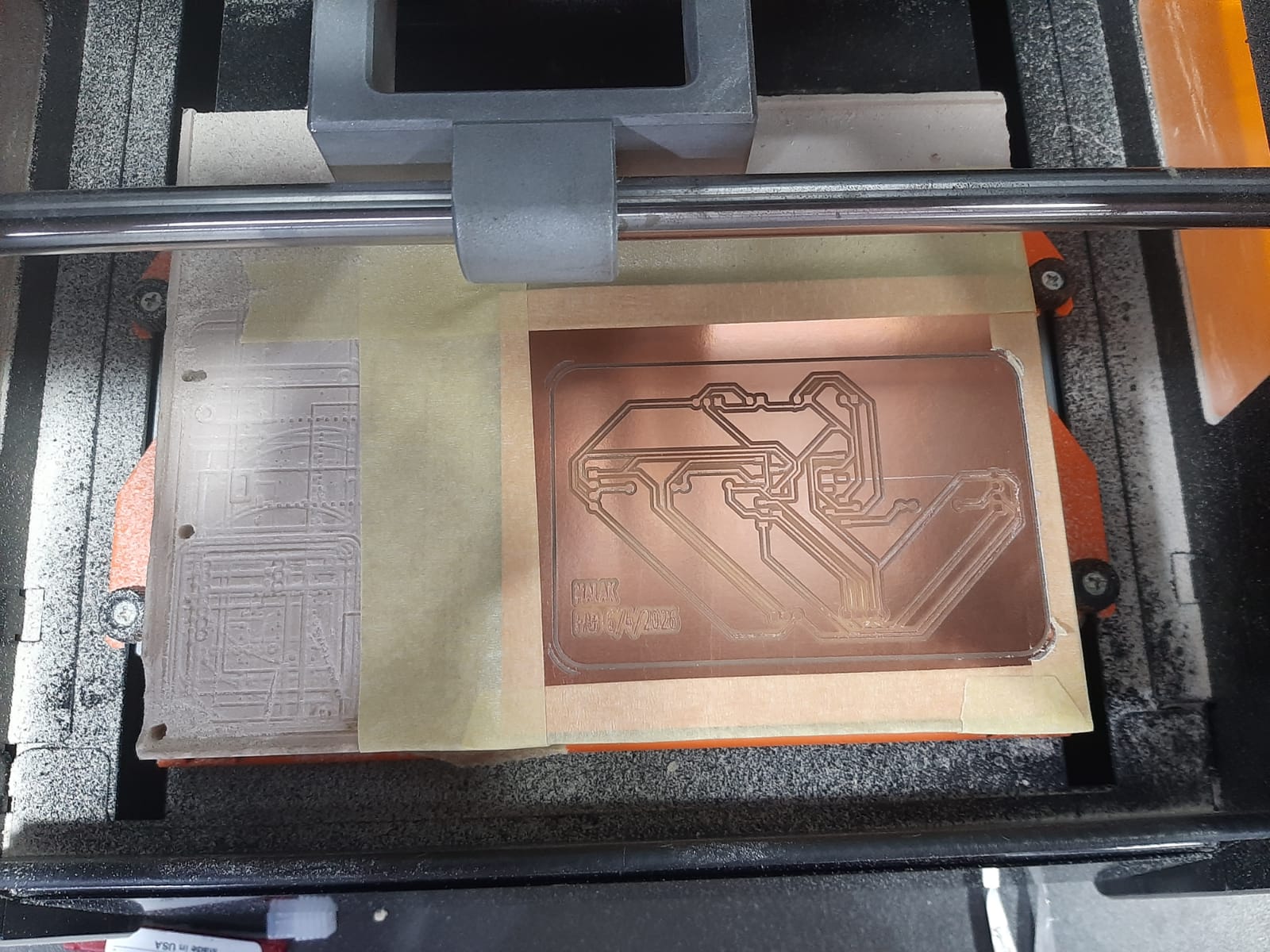
The PCB was designed using KiCad and fabricated using an SRM-20 milling machine. The board was sized to fit the project and accommodate the necessary components, including the microcontroller, sensors, and power supply.
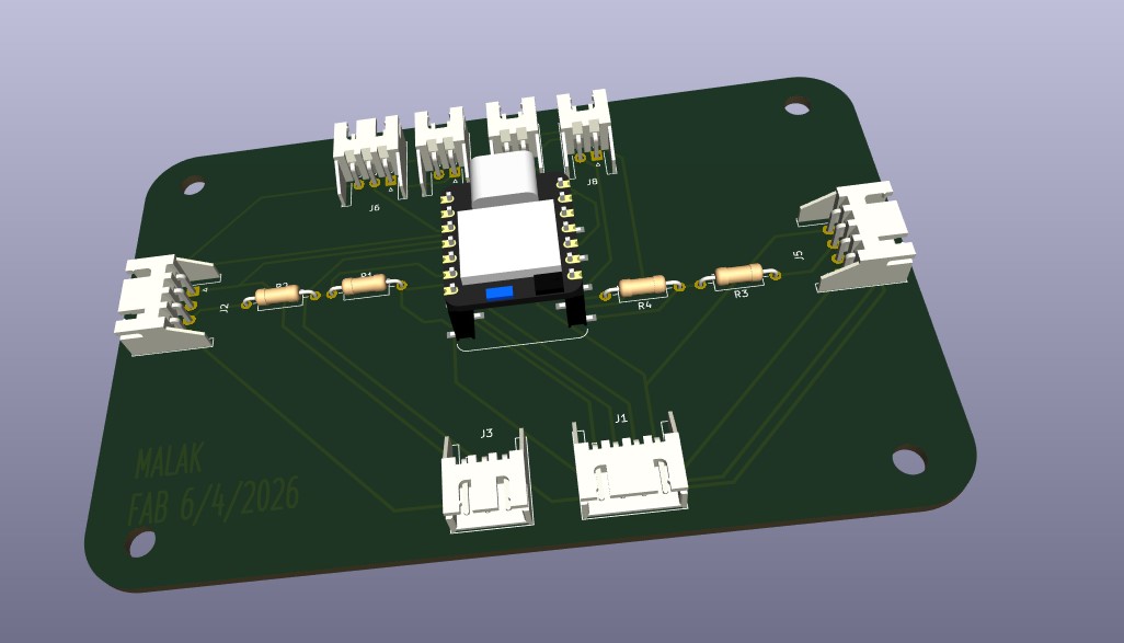
Here is the schematic and PCB design:
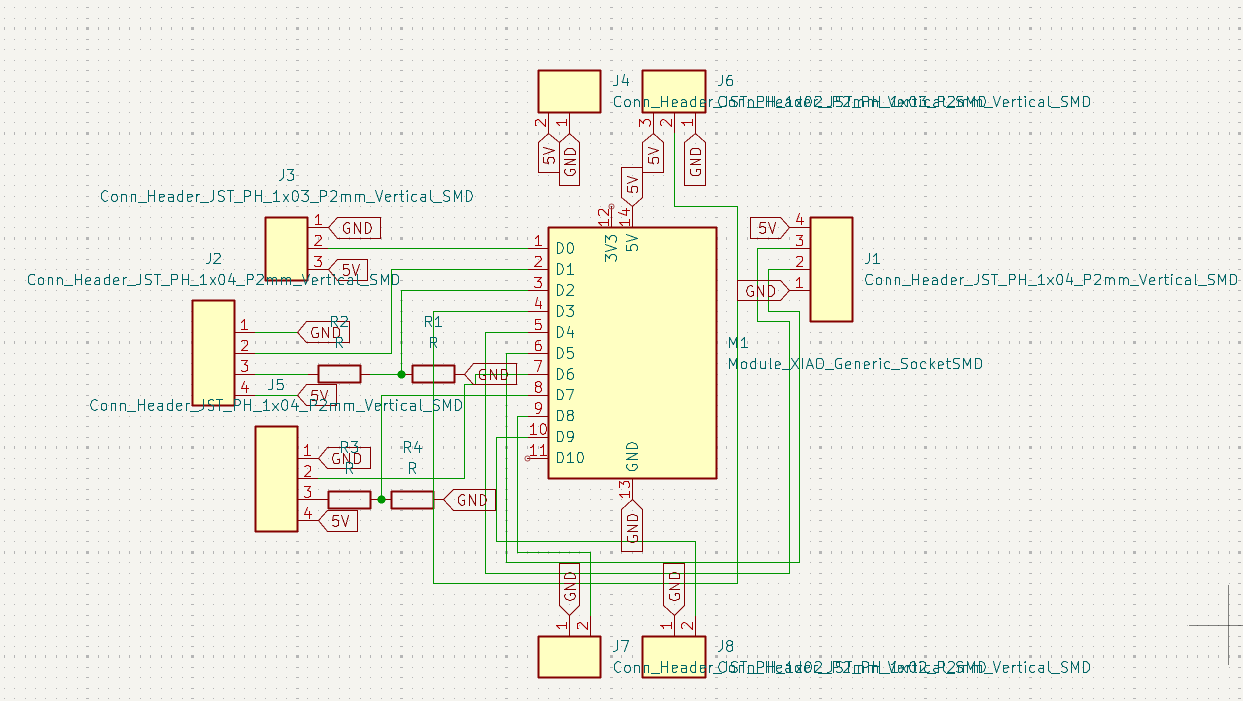
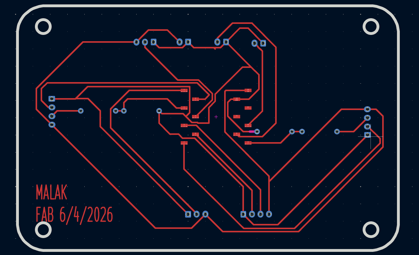
Here is the KiCad project file: PCB KiCad Project
Here are the extracted files: PCB Extracted Files
Here is the final result after milling the PCB:
After completing the manufacturing process, next step is to assemble all the parts together and test the final product to ensure that it meets the design specifications and functions as intended.