Week 7: Computer-Controlled Machining
Group Assignment
For the group assignment, we had to test the CNC machine and know its specifications and capabilities. We also had to cut something simple using the CNC machine to test it and understand how it works.
I could see the full group assignment Group Assignment Documentation.
Individual Assignment
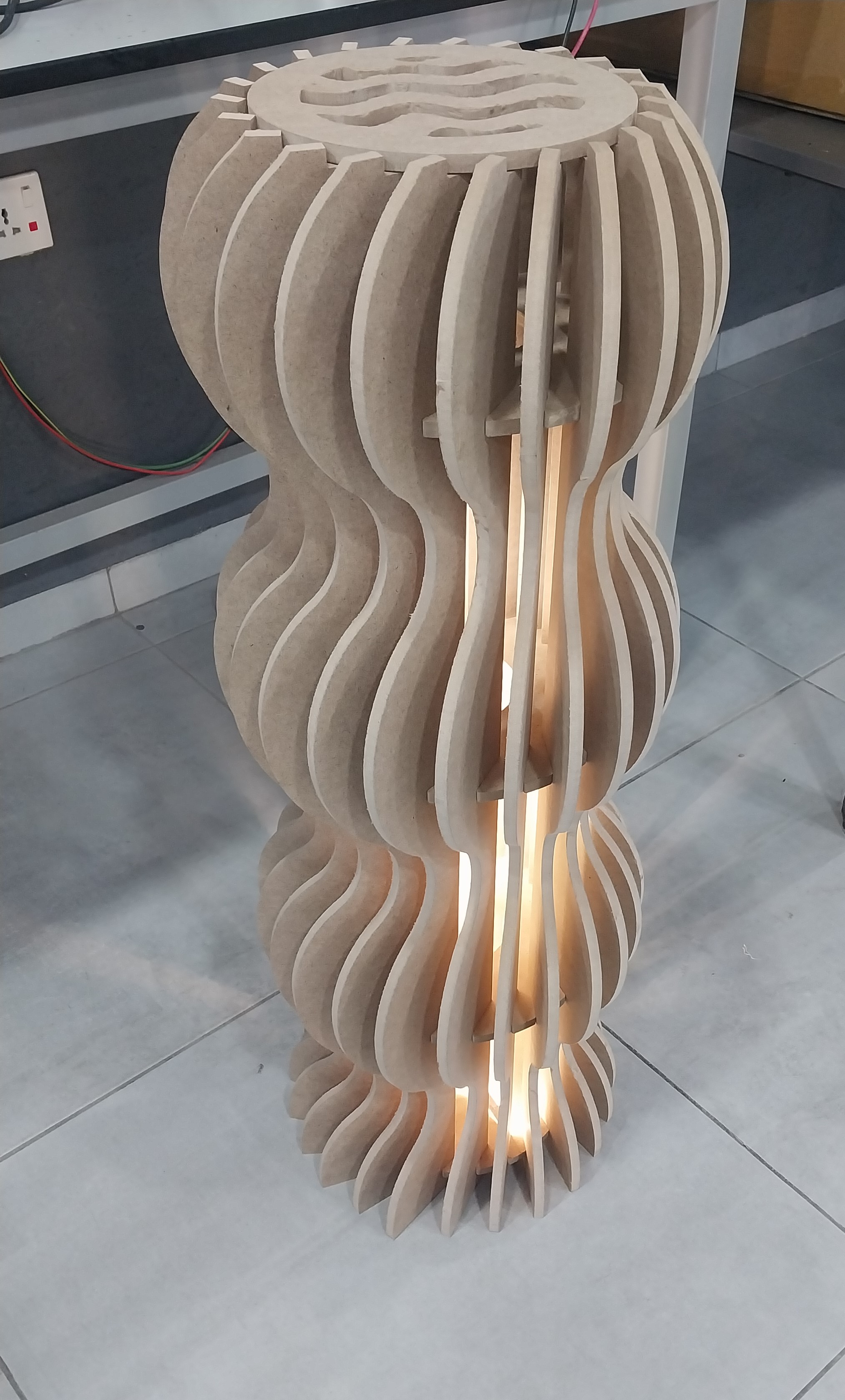
Hero Shot:
Safety Guidelines:
When using the CNC machine, it is important to follow safety precautions to prevent accidents and injuries. Here are some safety tips to keep in mind:
- Always wear safety goggles to protect your eyes from flying debris.
- Wear ear protection to protect your hearing from the loud noise of the machine.
- Keep your hands and fingers away from the cutting area while the machine is in operation.
- Make sure the workpiece is securely clamped to the machine bed before starting the machine.
- Do not wear loose clothing or jewelry that could get caught in the machine.
- Be aware of your surroundings and keep a safe distance from the machine while it is in operation.
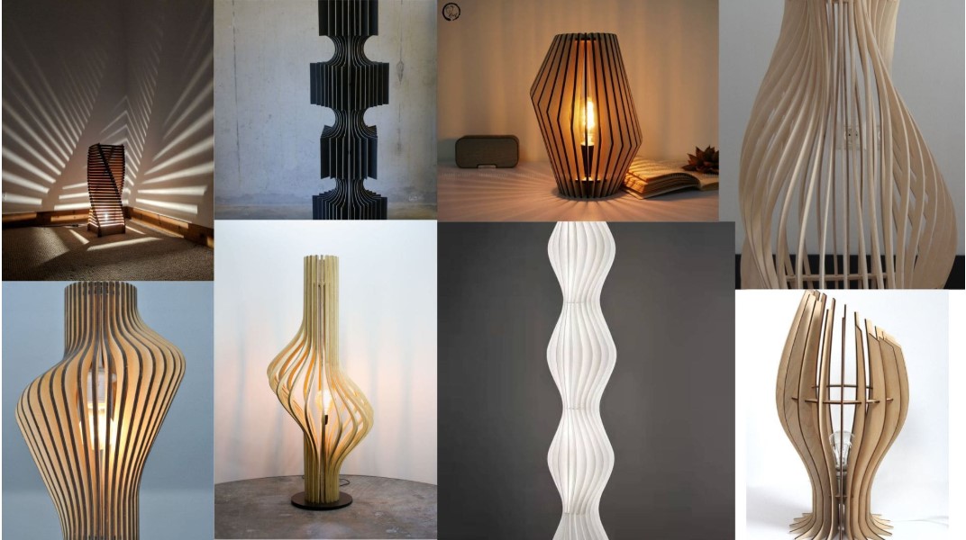
Inspiration:
For the individual assignment, I cut two pieces of wood using the CNC machine:
- Floor Lamp:
- Spice Rack:
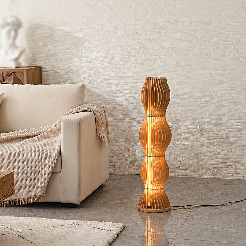
I was inspired by a modern wooden floor lamp design.
I wanted to do this without glue or screws at all.
I was inspired by the need for a spice rack in my kitchen.

I wanted to create this with a different wood type and try working with wood glue and its process, since I had never done such a thing before.
Design Process:
- Floor Lamp:
I used this picture as a reference to design the floor lamp in Fusion 360.
Here is the parametric list for my design:
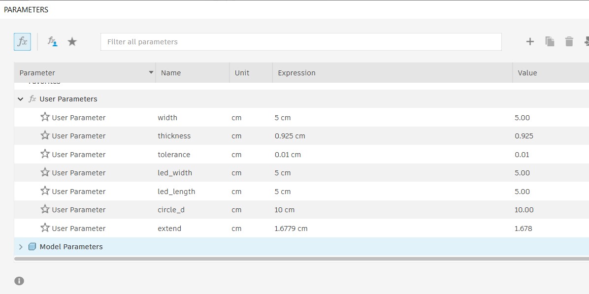
- Here is my 3D model of the floor lamp that I designed in Fusion 360:
- Spice Rack:
And here is the .stl file for the floor lamp design: Download
I designed the spice rack in Fusion 360.
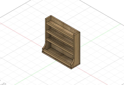
Here is a 3D view of the spice rack design:
Here is the Fusion 360 file for the spice rack design: Download
Here is the .stl file for the spice rack design: Download
Floor Lamp:
Setting Up the Model for Cutting:
- Using Fusion 360.
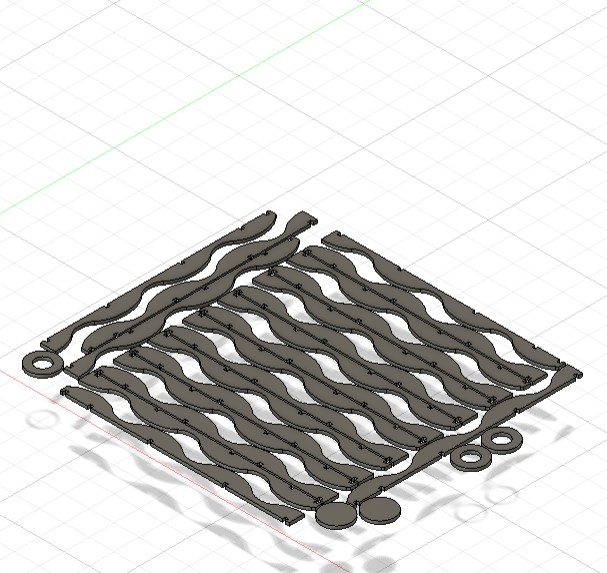
- First, I had to create a 2D projection of my model so I could cut it using the CNC machine. To do this, I used the Arrange tool, which is under the Modify tab in Fusion.
 💡 Note: Make sure to convert all the bodies to components so the Arrange tool works correctly.
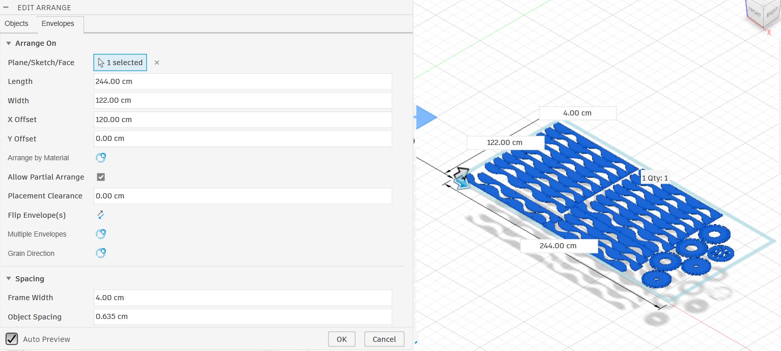
Make sure to set the length and width of the arrangement according to the actual size of the wood you will cut. Also, set the spacing between the pieces to be at least (tool diameter * 2 + 4 mm) to allow enough space for cutting. Do not forget to set the board offset when fixing it; I usually set the offset to 4 cm so it is easier to attach the screws.
Here is the model after using the Arrange tool.
- Then I went to the Manufacturing workspace so I could define the toolpath and other specifications for the cutting process.
- In the Manufacturing workspace, I created a new setup for the model and set its specifications, such as the operation type, stock size, and origin point.
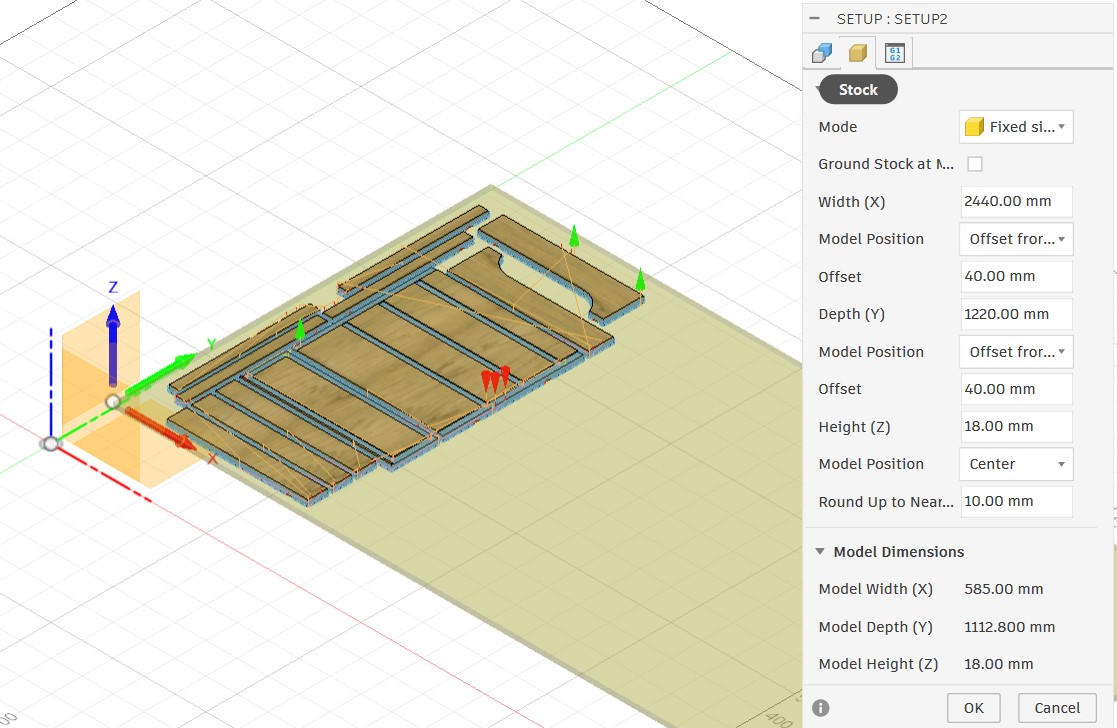
- Stock Settings
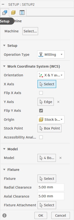
- Setup Settings
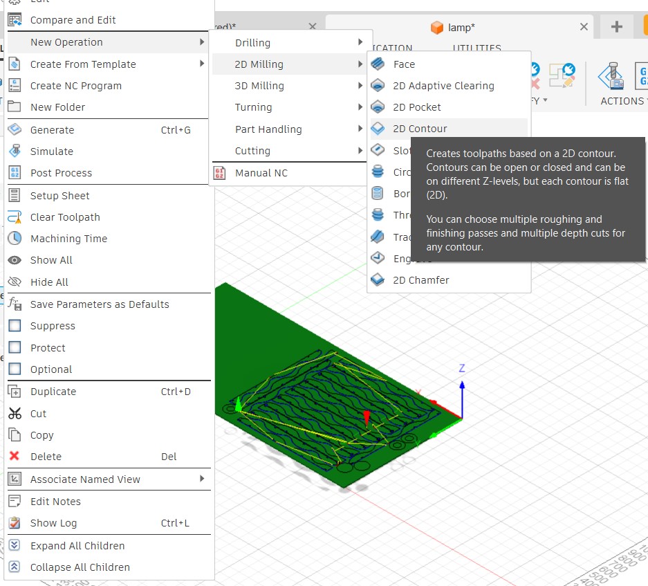
- After finishing the setup, I had to create a new operation.
- Create New Operation
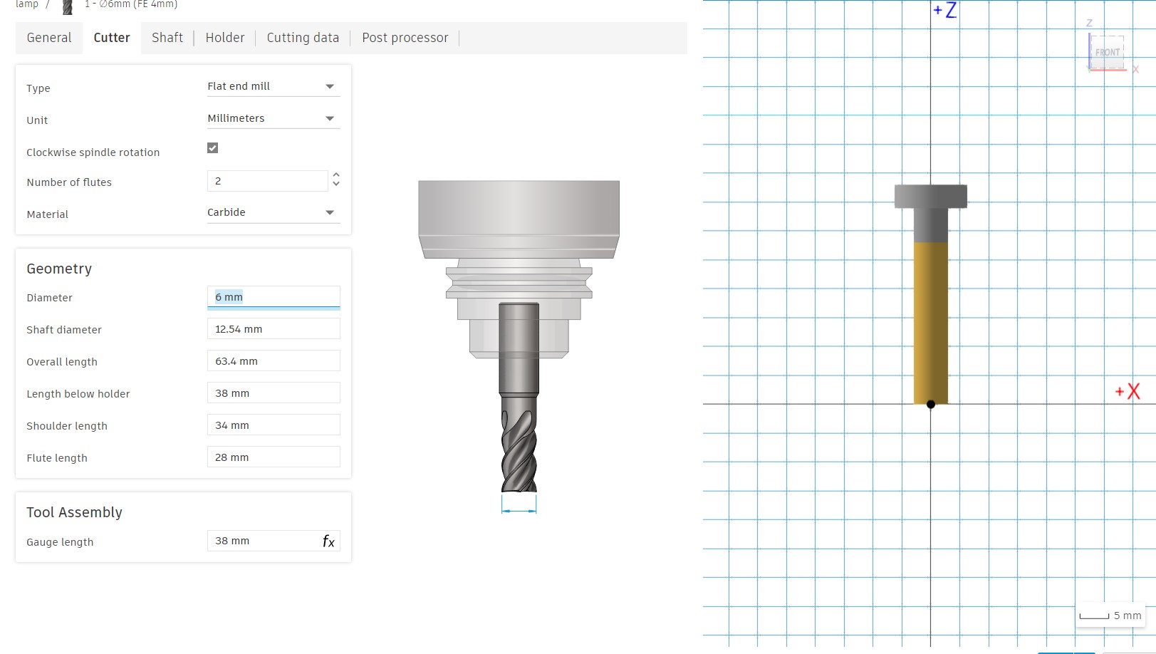
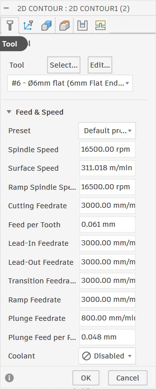
- Select tool:
- Define the cutting parameters:
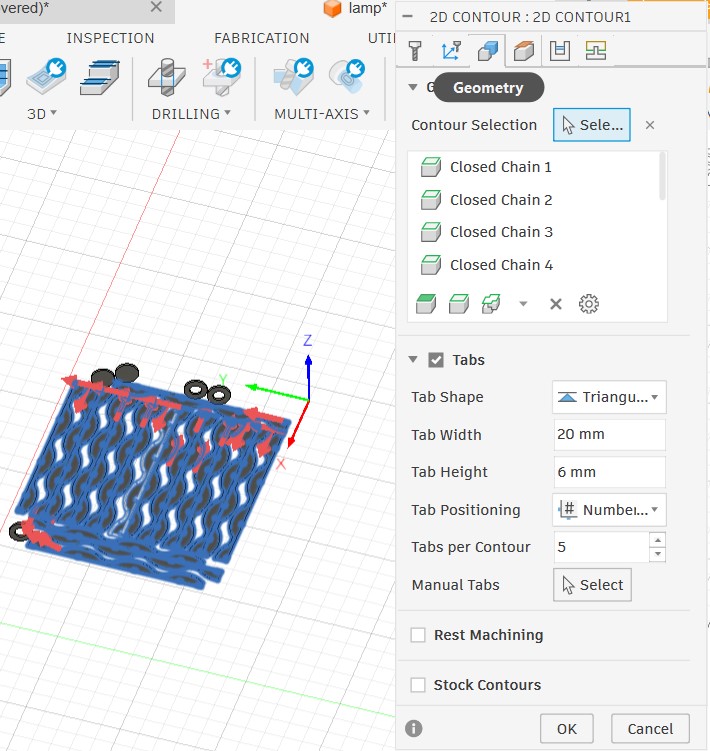
- Geometry Settings
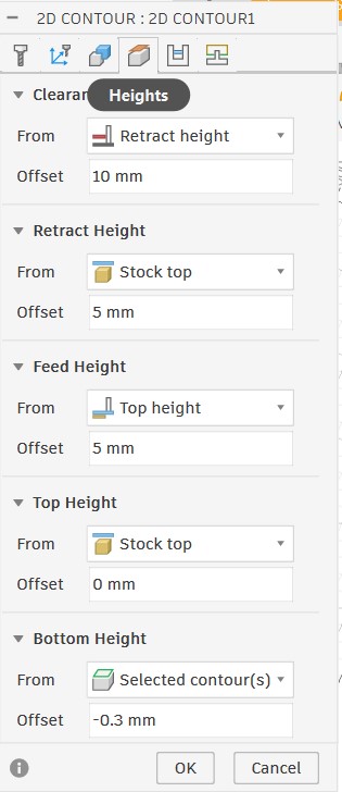
- Height Settings
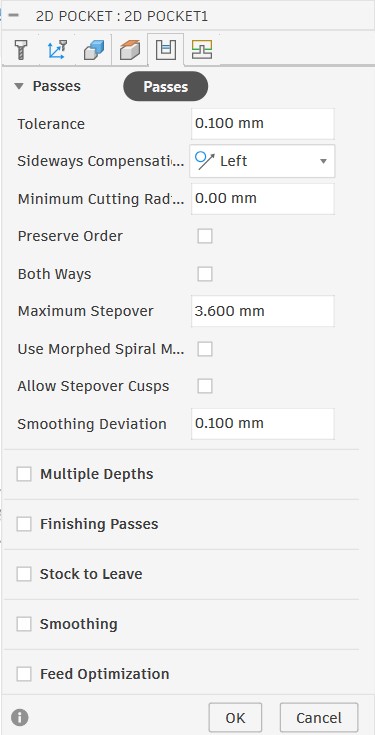
- Passes Settings
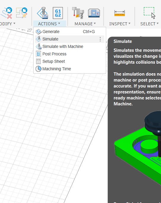
- Simulation
I will explain the full setup process for the floor lamp using the Fusion Manufacturing workspace.
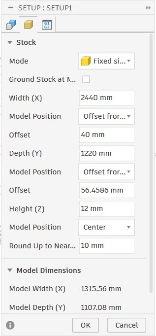
I set the mode to Fixed Size so I could select my model and set the stock dimensions according to the wood dimensions I would cut. I also set the origin point at the top-left corner of the stock and added an offset of 40 mm to leave enough space for screws to secure the stock on the CNC machine.
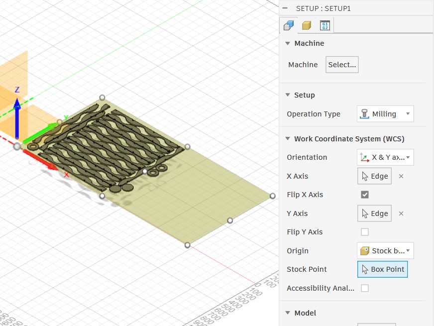
For setup, I specified the operation type and selected one edge to be parallel to the X-axis and another edge to be parallel to the Y-axis.
To create a new operation, right-click the setup, select the operation type, then choose the path strategy you want to use.
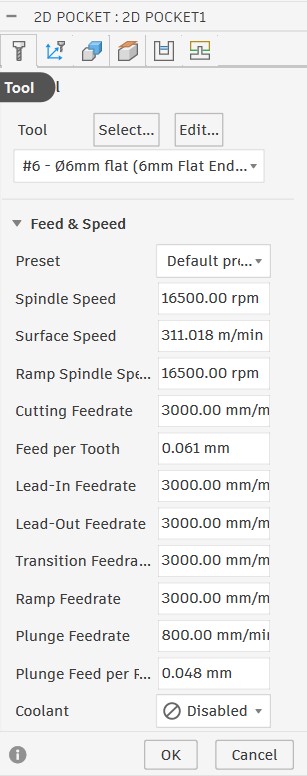
After creating a new operation, I selected the cutting tool. I used a flat end mill with a 3.2 mm diameter and set all the required parameters.
After selecting the tool, I defined the cutting parameters, such as the feed rate and spindle speed.
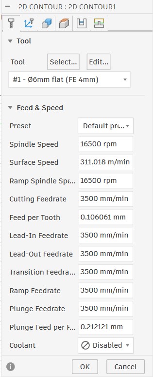
To find the exact values for these parameters, I used the FSWizard website: link.
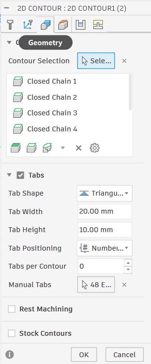
After defining the cutting parameters, I selected the contour and highlighted the areas that needed to be cut from the bottom. I also enabled Tabs, which I could place manually or automatically, to prevent the piece from moving after cutting and causing damage during the process.
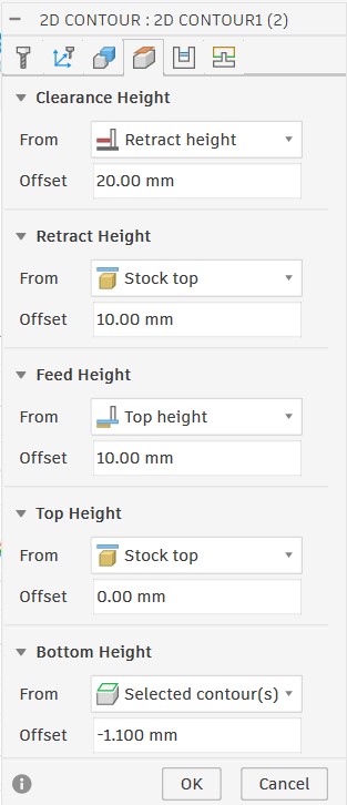
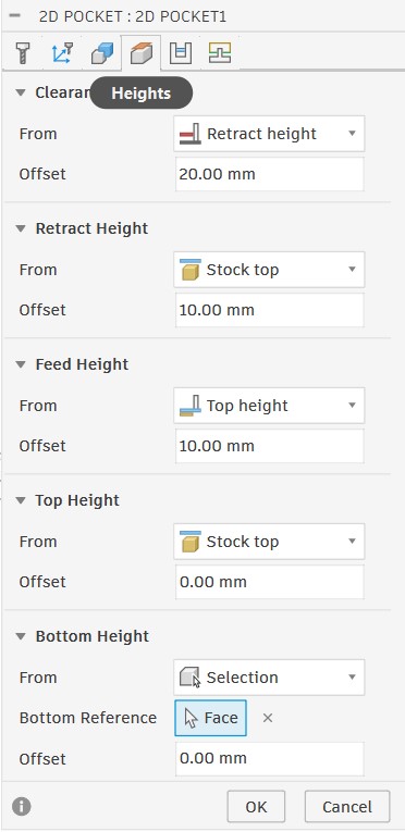
In the height settings, I set the top height to the stock top and the bottom height to 5 mm below the stock bottom to ensure the tool would cut through the wood.
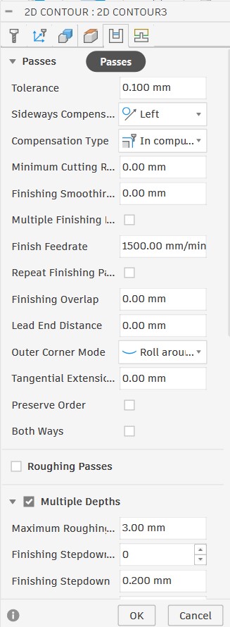
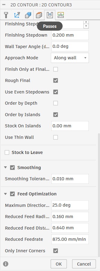
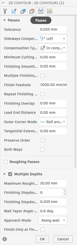
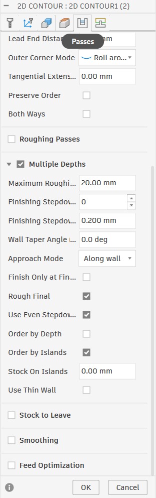
In the passes settings, I enabled Multiple Depths, checked "Use even Stepdown & Order by Island," and enabled feed optimization.
After finishing all the settings, I ran the simulation to make sure everything was correct before cutting.
Here is the simulation result, showing the toolpath and how the CNC machine would cut the piece.
It is important to check that the piece is fully cut before starting the actual cutting process by running the simulation first.
Setting Up the CNC Machine:
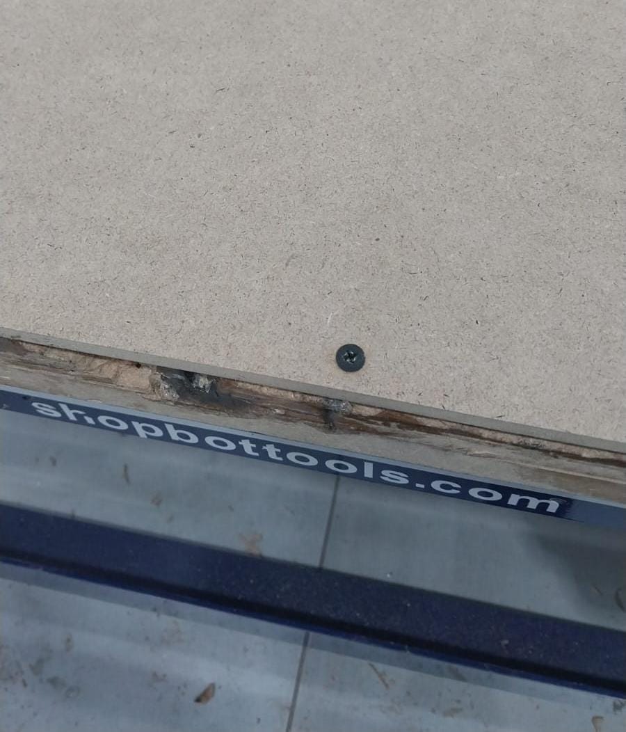
- First, we have to remove the old board if there is one, and place our working board in its place.
- Then, we have to secure the board using screws to make sure it is fixed and will not move during the cutting process.
- After that, we have to set up the tool by installing it in the spindle and tightening it properly, after removing the old tool if there is one.
- Next, we have to set the origin for the machine (X, Y, Z).
- To set the X and Y origin, we have to move the tool to the top-left corner of the board and set it as the origin.
- To set the Z origin, I use an electric device that helps zero the tool by detecting when it touches the board. I place it under the tool, lower the tool until it is slightly above the device, then the device does its work and sets the Z origin. Here is a video that shows the process.
- Finally, before turning the machine on, set Z to 30 mm above the board and set X and Y to the origin.
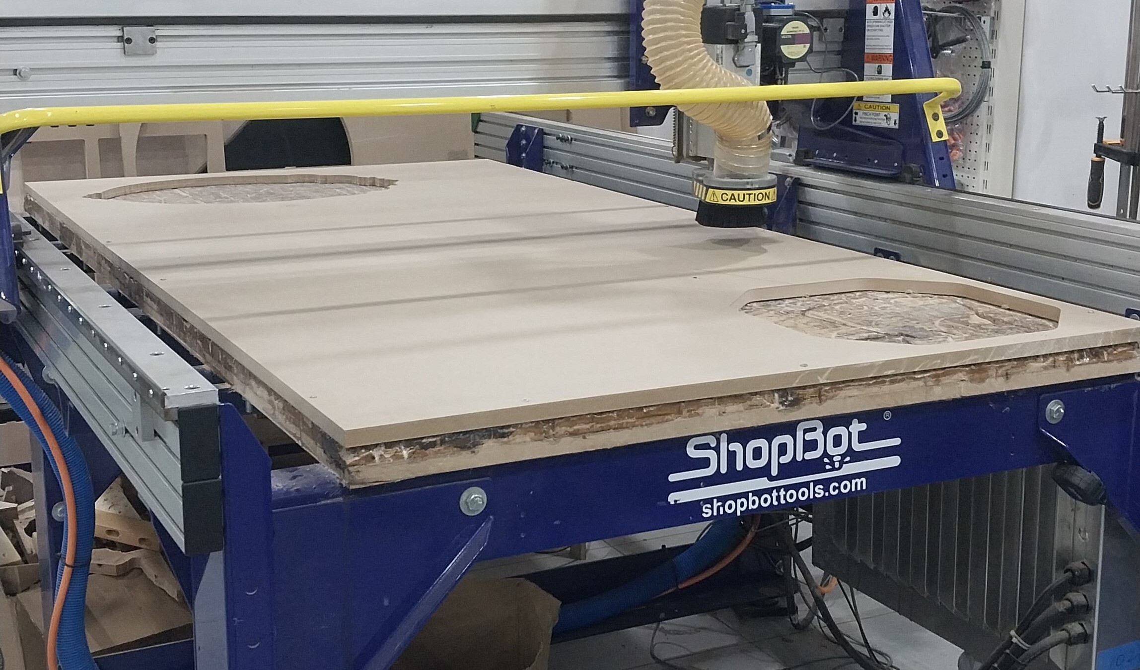
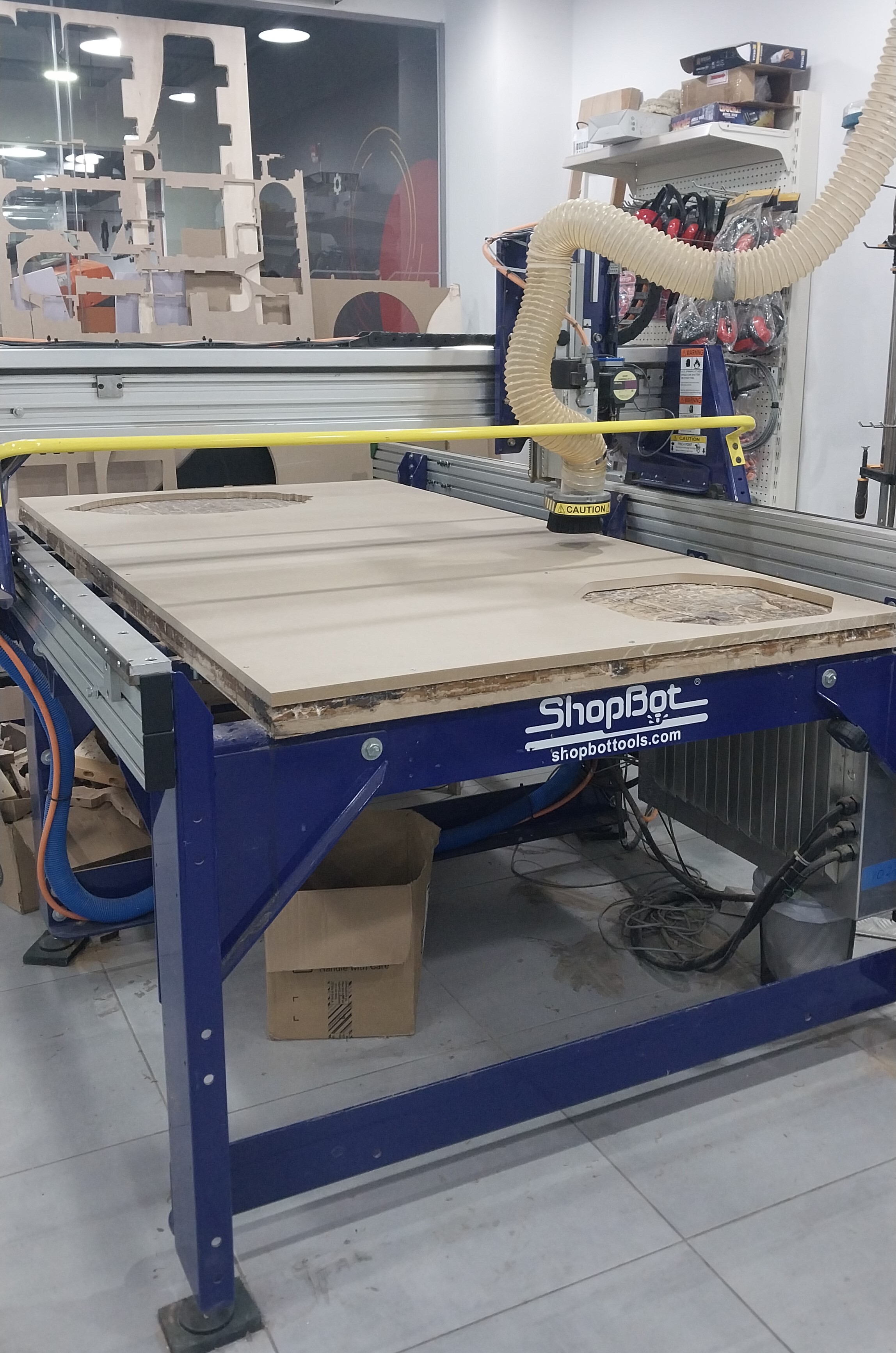
Our CNC Machine:
The CNC machine we used is a ShopBot PRSalpha, which has a working area of 4 feet by 8 feet and can cut various materials, including wood, plastic, and some metal like aluminum.
Here are the setup steps for the CNC machine:
Upload cutting file & turn on machine
After setting up the machine and generating the toolpath, we can upload the cutting file to the CNC machine and turn it on by following these steps:
- First, we have to export the G-code file from Fusion 360 and save it on a USB drive.
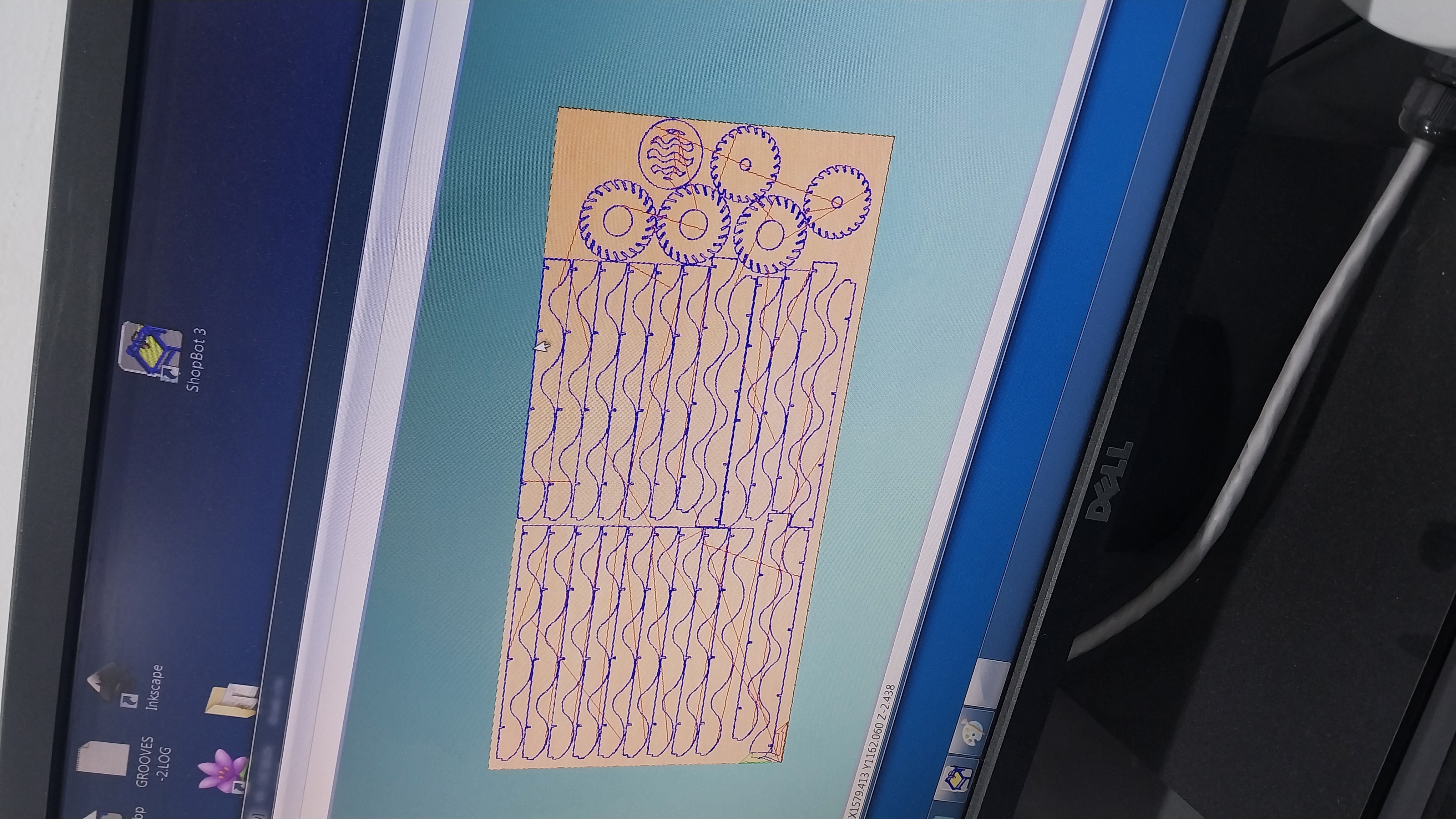
- After that, we have to insert the USB drive into the CNC machine and upload the G-code file.
- Next, preview the cutting path on the machine to ensure it is correct.
- Finally, we can turn on the machine and start cutting.
To export the G-code file, select Actions and then Post Process.
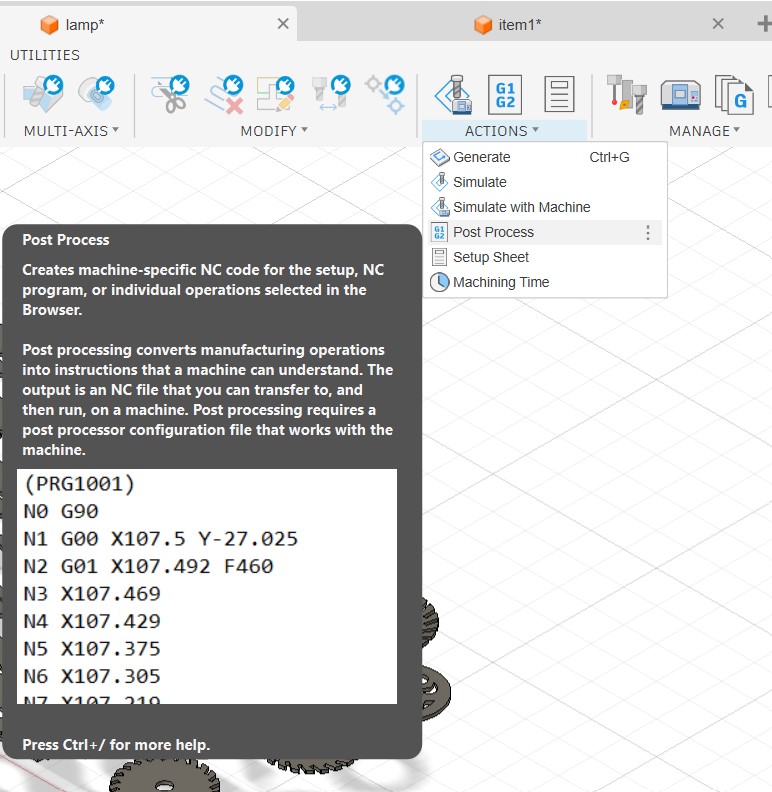
Then, verify and check that the toolpath and other settings are correct, select the correct post processor for the CNC machine, and click Post to export the G-code file.
Cutting Process and Results
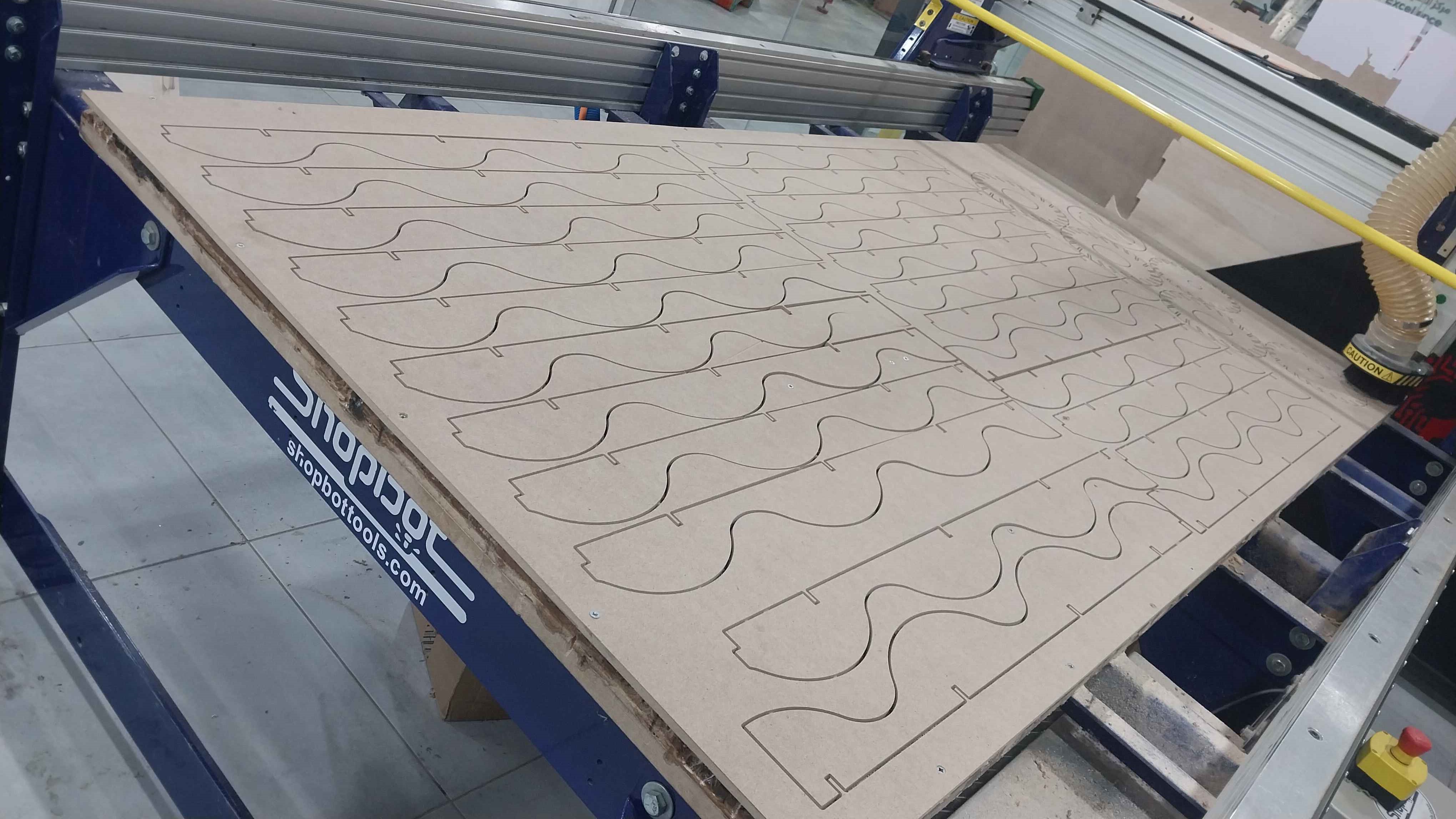
- Here are some videos showing the cutting process for both the floor lamp.
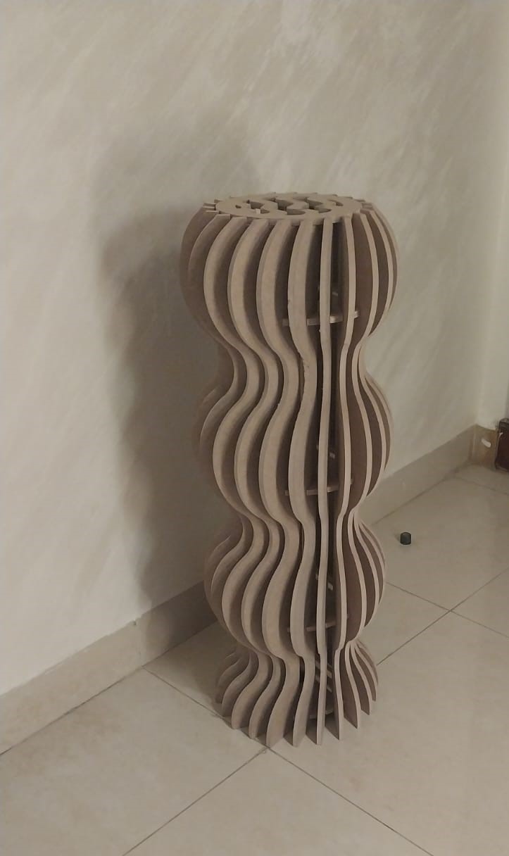
- And here is the final result for the floor lamp after cutting.
- I have to remove the tabs first.
- Next, I did the finishing touches.
- Finally, I assembled the pieces together to get the final result.
- And here is the final result for the floor lamp.
Spice Rack:
In this model, my target was to deal with different materials, multiple toolpaths for the same model, and to try working with wood glue for assembling the pieces together. So I used a different design and cutting process than the floor lamp. Here are the steps I followed:
Setup settings
- Stock settings
- Setup settings
Toolpaths Settings
Contour
- Tool selection
- Geometry settings
- Passes settings
- Height settings
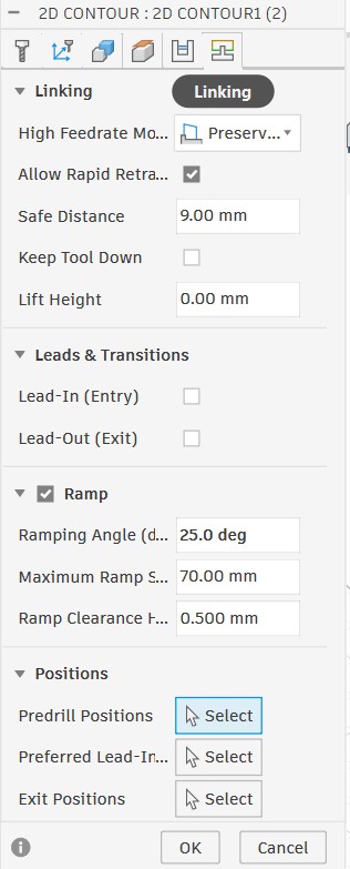
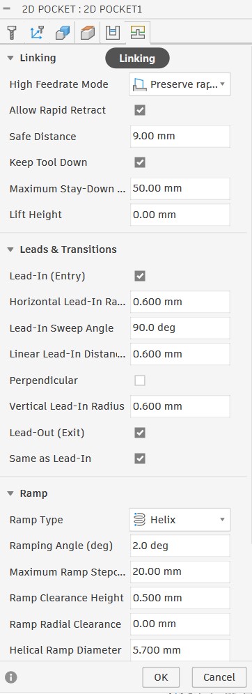
- Linking settings
Pocket
- Tool selection
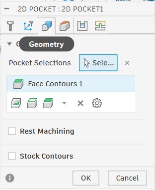
- Geometry settings
- Passes settings
- Height settings
- Linking settings
Simulation
- Contour simulation
- Pocket simulation
- First, I exported the G-code files for both toolpaths and saved them on a USB drive.
- Then, I inserted the USB drive into the CNC machine and uploaded the G-code files.
- Next, I previewed the cutting path for both toolpaths on the machine to ensure they were correct.
Setting Up the Model for Cutting
The setup process for the spice rack was similar to the floor lamp, but with some differences in the settings. Here are the main differences:
Here is the setting for the spice rack:
Setting Up the CNC machine
The setup process for the CNC machine was the same as the floor lamp, but I had to change the tool and adjust the Z origin according to the new tool length.
Upload Cutting File & Turn On Machine
The process of uploading the cutting file and turning on the machine was the same as the floor lamp, but I had to upload two different G-code files for the two different toolpaths.
Cutting Process & Results
Cutting Process
The cutting process for the spice rack was similar to the floor lamp, but I had to cut the pocket toolpath first to ensure that the pieces would not move during pocketing. Here are some videos showing the cutting process for both toolpaths.
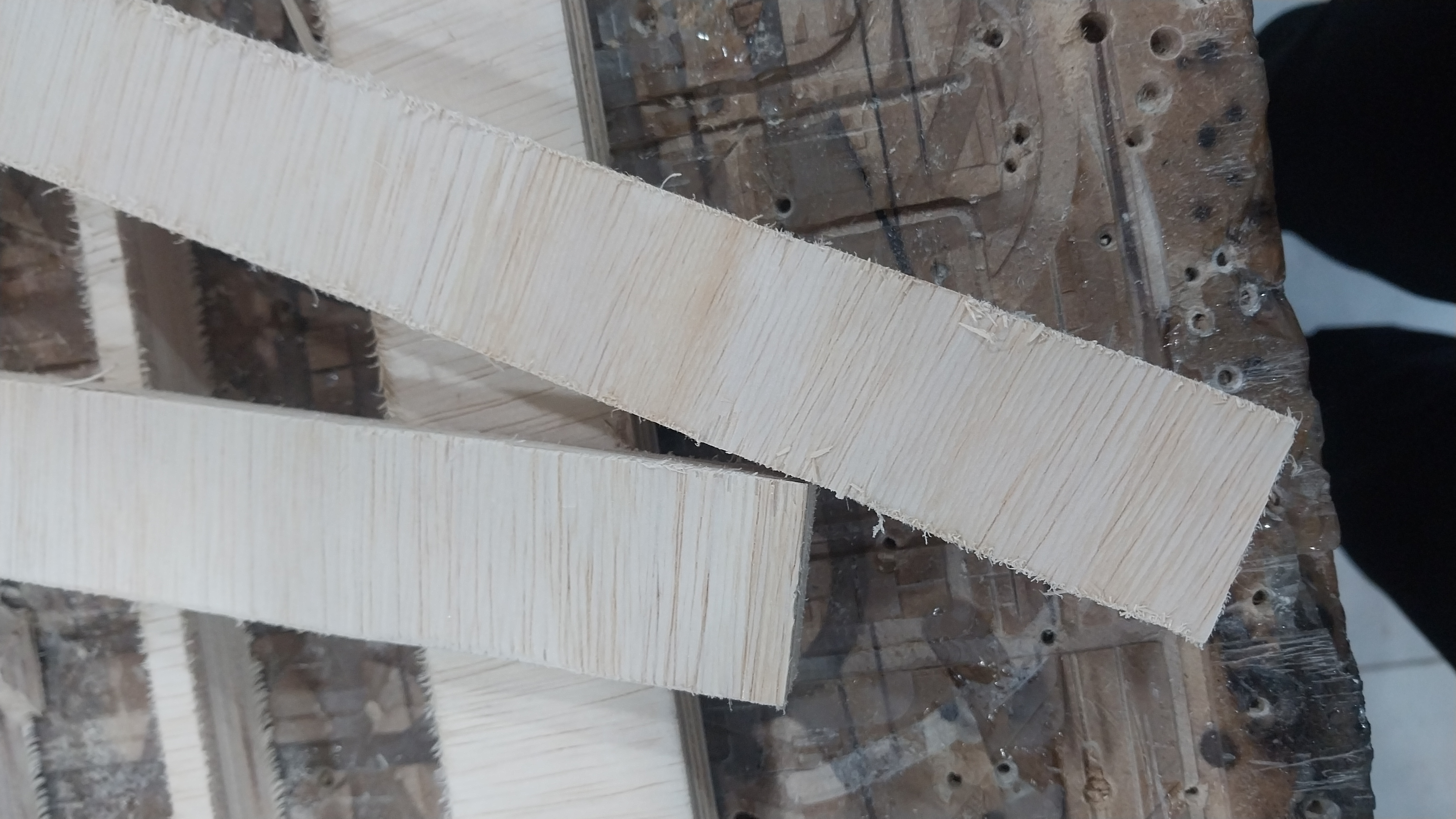
Finishing
After the cutting process, since I used plywood, I had to do some finishing touches to get rid of the rough edges and make the pieces look better. I used sandpaper for sanding the edges and then applied a wood finish to enhance the wood's appearance and protect it.
Here is the difference before finishing and after:
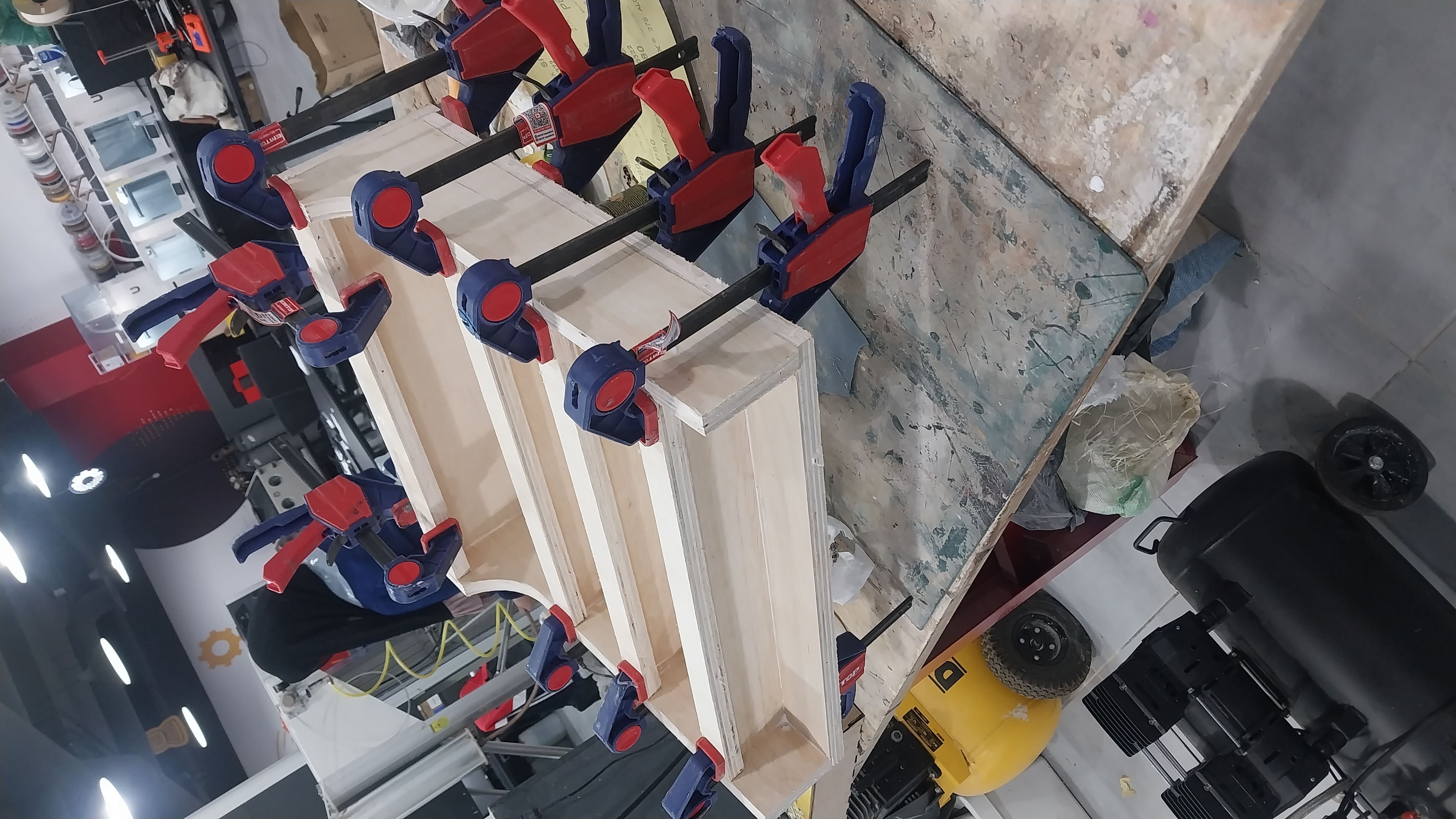
Assembly
After finishing the pieces, I assembled them together using wood glue.
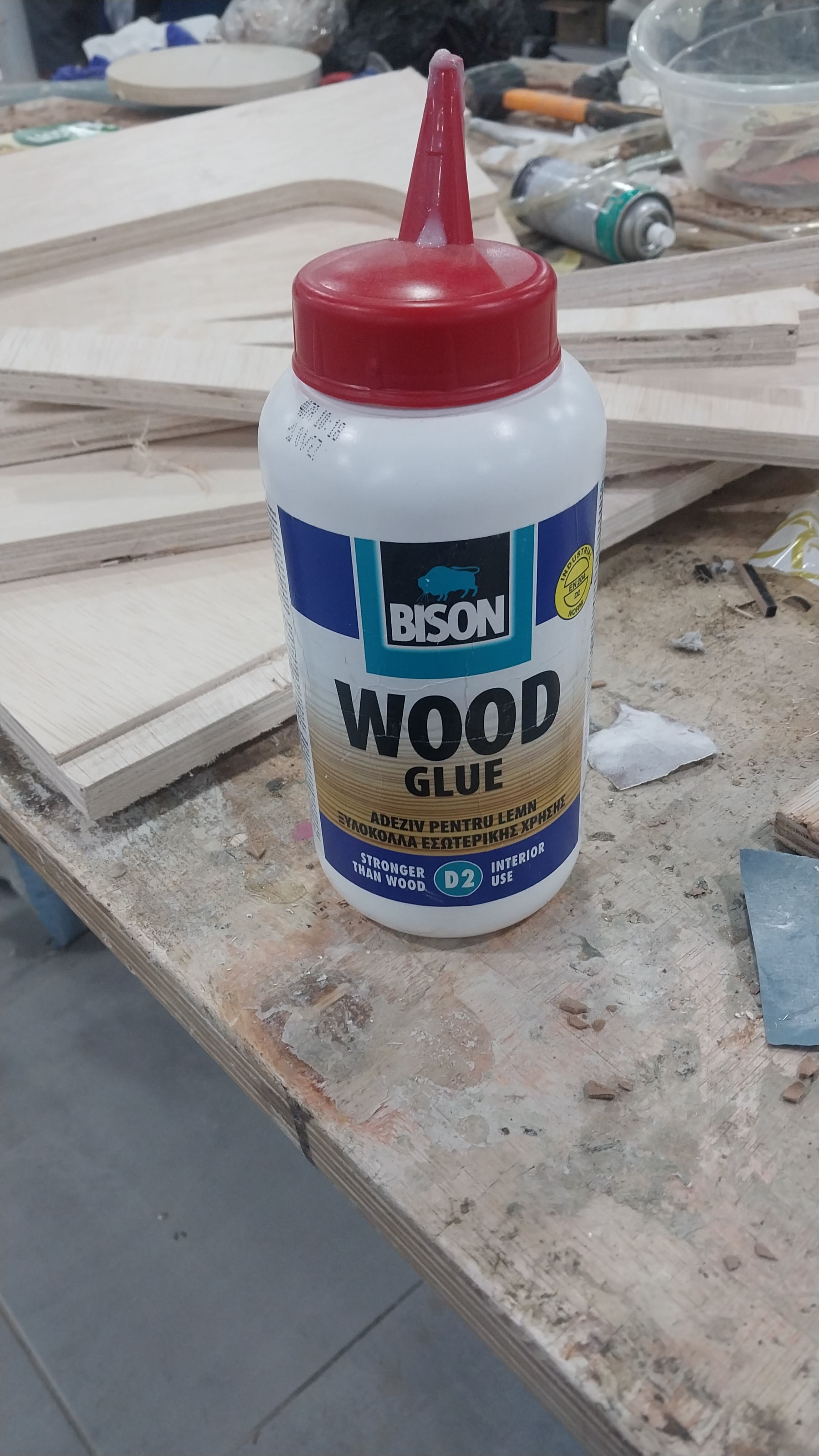
And here is the gluing process:
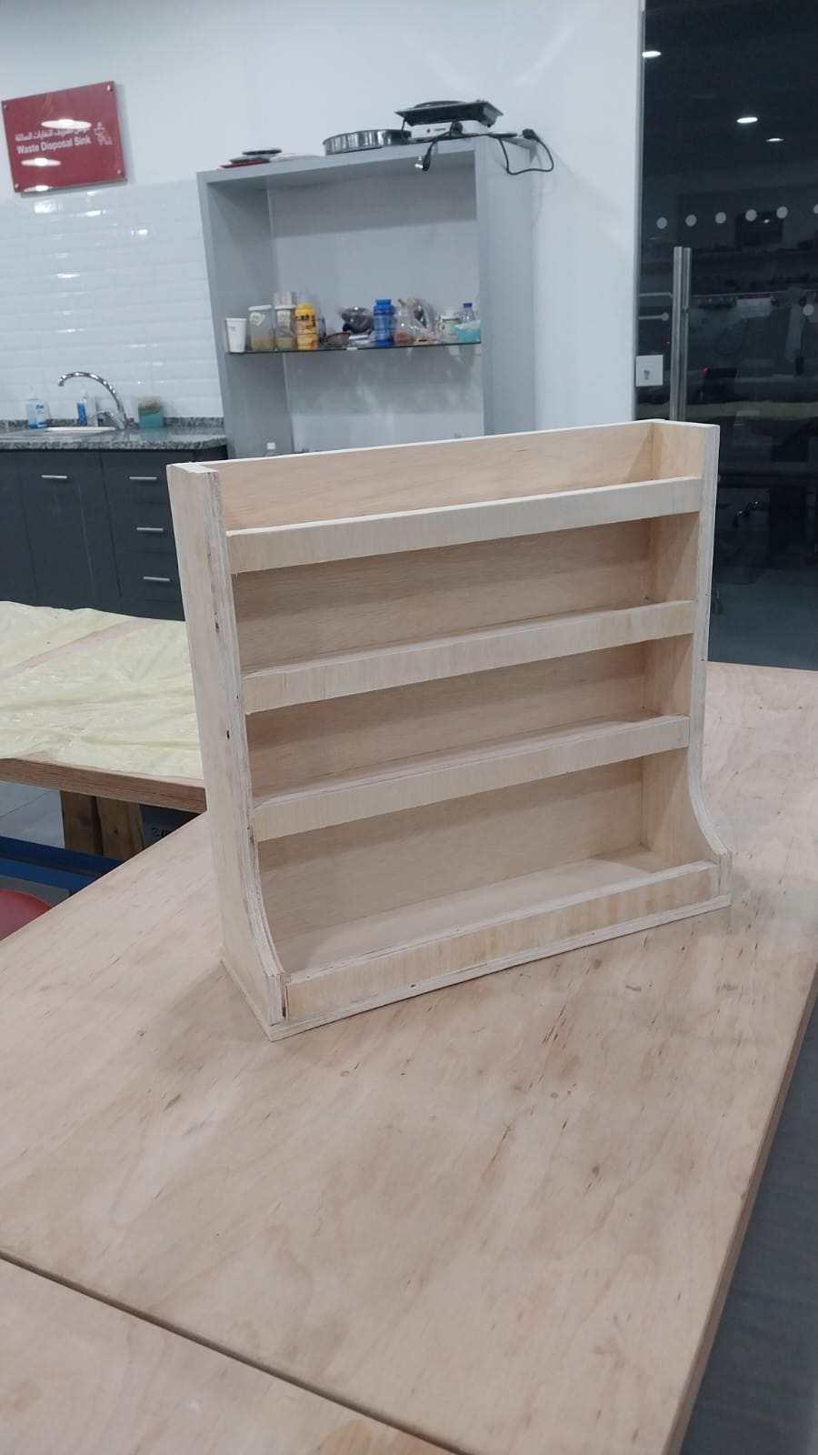
Here is the spice rack after assembly:
And here is the final result for the spice rack.