Final Project - Zakkerni
Video Presentation
Slide Presentation
Project Overview:
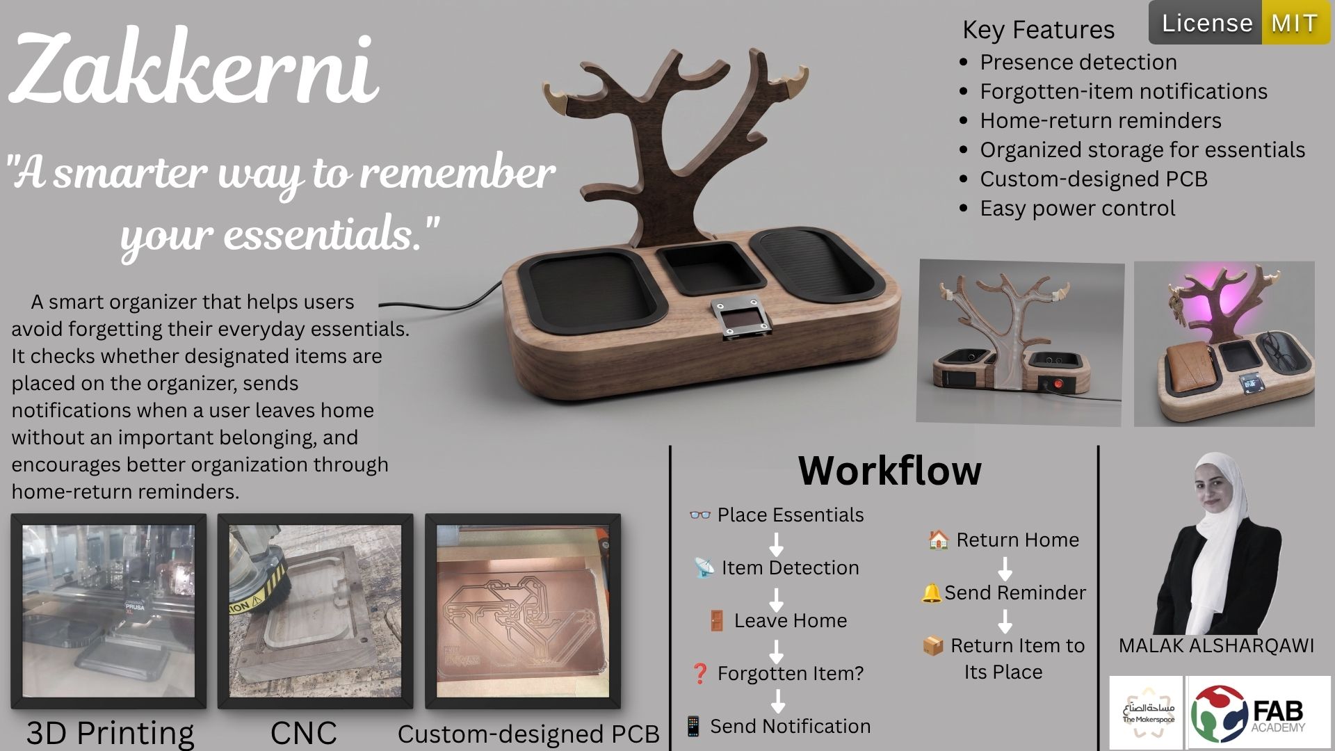
The Zakkerni A smart organizer that helps users
avoid forgetting their everyday essentials. It checks whether designated items are placed on the organizer, sends notifications when a user leaves home without an important belonging, and encourages better organization through home-return reminders.
License
The Zakkerni project is shared under MIT License, allowing others to freely use, modify, and distribute the project for educational and personal purposes. The project is open-source, and the design files, code, and documentation are available for anyone interested in learning from or contributing to the development of Zakkerni.
 MIT License

Copyright (c) 2026 Malak Alsharqawi

Permission is hereby granted, free of charge, to any person obtaining a copy
of this software and associated documentation files (the "Software"), to deal
in the Software without restriction, including without limitation the rights
to use, copy, modify, merge, publish, distribute, sublicense, and/or sell
copies of the Software, and to permit persons to whom the Software is
furnished to do so, subject to the following conditions:

The above copyright notice and this permission notice shall be included in all
copies or substantial portions of the Software.

THE SOFTWARE IS PROVIDED "AS IS", WITHOUT WARRANTY OF ANY KIND, EXPRESS OR
IMPLIED, INCLUDING BUT NOT LIMITED TO THE WARRANTIES OF MERCHANTABILITY,
FITNESS FOR A PARTICULAR PURPOSE AND NONINFRINGEMENT. IN NO EVENT SHALL THE
AUTHORS OR COPYRIGHT HOLDERS BE LIABLE FOR ANY CLAIM, DAMAGES OR OTHER
LIABILITY, WHETHER IN AN ACTION OF CONTRACT, TORT OR OTHERWISE, ARISING FROM,
OUT OF OR IN CONNECTION WITH THE SOFTWARE OR THE USE OR OTHER DEALINGS IN THE
SOFTWARE.
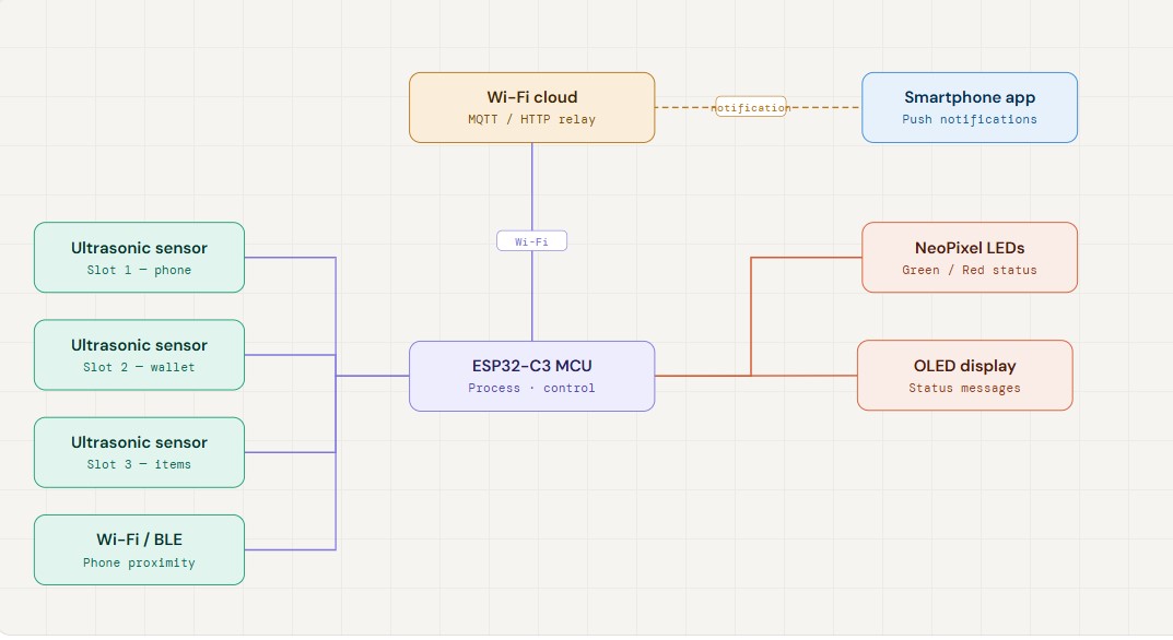
System Diagram
Materials
The system is built using a Seeed XIAO ESP32-C3 microcontroller, ultrasonic sensors, IR sensors, push buttons, LEDs, jumper wires, a power adapter, and 3D-printed components for the organizer structure. Most required components are available in the laboratory; any additional parts can be purchased from local electronics stores.
Bill of Materials — Zakkerni
Smart organizer · ESP32-C3 based
| # | Component | Description | Category | Source | Price per Unit | Qty | Subtotal |
|---|---|---|---|---|---|---|---|
| 1 | Seeed XIAO ESP32-C3 | Main microcontroller with Wi-Fi & BLE | MCU | Fab Inventory | $5.00 | 1 | $5.00 |
| 2 | Ultrasonic Sensor (HC-SR04) | Item presence detection | Sensor | local store | $3.53 | 2 | $7.06 |
| 3 | IR Sensor | Secondary item detection | Sensor | local store | $2.82 | 1 | $2.82 |
| 4 | Push Button | User input / manual trigger | Input | local store | $0.21 | 2 | $0.42 |
| 5 | NeoPixel strip | Light Effects | Output | lab storage (available on Amazon) | $13.00 | 1 | $13.00 |
| 6 | OLED Display 1.3 inch | Visual feedback on organizer | Output | local store | $8.46 | 1 | $8.46 |
| 7 | XH2.54mm Bend Pin Header Connector | connections | Misc | local store | $0.28 | 8 | $2.24 |
| 8 | JST XH 2.54mm | connections | Misc | local store | $0.63 | 8 | $5.04 |
| 9 | USB cable and adapter | Main power supply | Power | lab storage (available on Amazon) | $10.00 | 1 | $10.00 |
| 10 | ON/OFF Power Switch | Power control | Power | local store | $0.85 | 1 | $0.85 |
| 11 | DC Power Supply Plug Connector + Female Jack | Power connection | Power | local store | $0.92 | 1 | $0.92 |
| 12 | Walnut 62cm | Manufacturer | Manufacturer | Lab Storage | 1 | $42.31 | |
| TOTAL | $107.54 |
Timeline
Weeks related to the final project
During different weeks on fab acadeMy Assignmentss I focused on the final project development here is the weeks which are related to my final project:
- Week 2: I did the first design using creo.
- Week 9: I tested different sensors and components that will be used in the final project, and created a sample slot to test on it.
- Week 10: Tested different output devices
- Week 11: Tested different communication protocols like Bluetooth and Wi-Fi
- Week 15: Tried different interfaces.
- Week 16: System Integration.
- Week 18: Applications and Implications, Project Development.
- Week 19: Invention, Intellectual Property and Income.