Week 4 : Embedded Programming
In week 4, we focused on embedded programming. We worked with microcontrollers and learned how to write code that interacts with hardware components. We also learned how to solder electronic components and understand GPIO (General Purpose Input/Output) pins.
1. Group Assignment
This week, we completed our second group assignment. In this assignment, we compared different types of microcontrollers based on their speed.
You can view the group assignment at the following link: Group Assignment
2. Individual Assignment
For the embedded programming assignment, I worked with two microcontrollers: Arduino Uno and Seeed ESP32.
| Arduino Uno | Seeed Studio XIAO ESP32C3 | |
|---|---|---|
| VERSION | UNO R3 | ESP32C3 |
| # OF PINS | 14 digital input/output pins 6 analog pins |
11 digital I/O 4 of them could be Analog |
| MICROCONTROLLER | ATMega328P | ESP32-C3 SoC |
| OSCILLATOR | 16 MHz crystal oscillator | 17.5 MHz crystal oscillator |
| MICROCONTROLLER DATA SHEET | ATmega328P Datasheet | ESP32-C3 Datasheet |
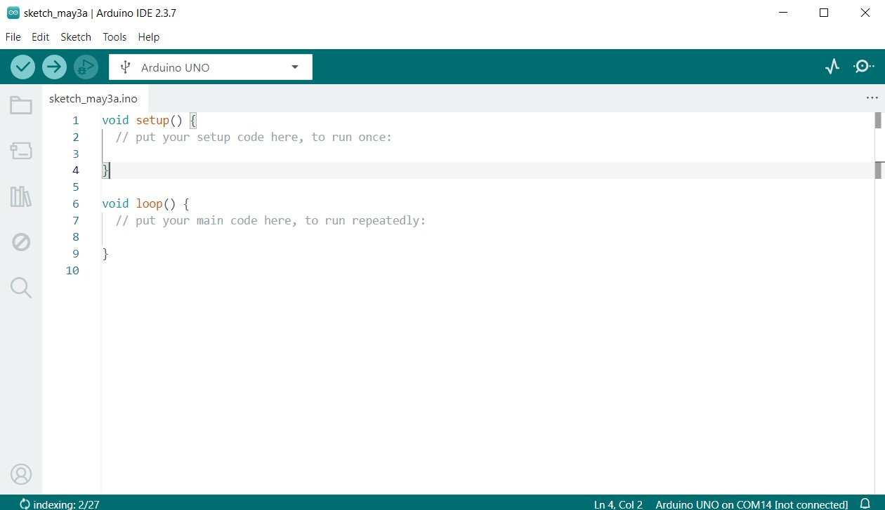
Arduino IDE
To do this week’s assignment, I used the Arduino IDE to write and upload code to the microcontrollers. The Arduino IDE is a popular development environment for programming Arduino boards and other compatible microcontrollers. It provides a user-friendly interface and a wide range of libraries and tools to make programming easier.
You could download the Arduino IDE from the official website: Arduino IDE Download
Arduino Uno
A. First Test
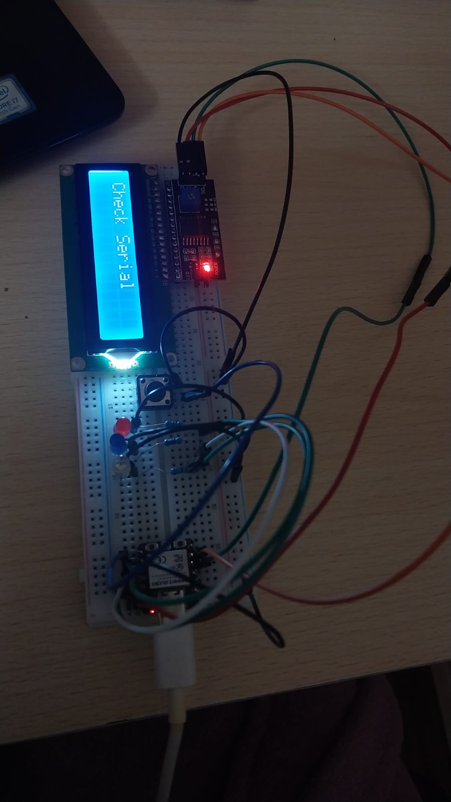
First, I made a Dino Run game on the Arduino Uno to focus on the physical connections and understand them better.
Here are the components that I used:
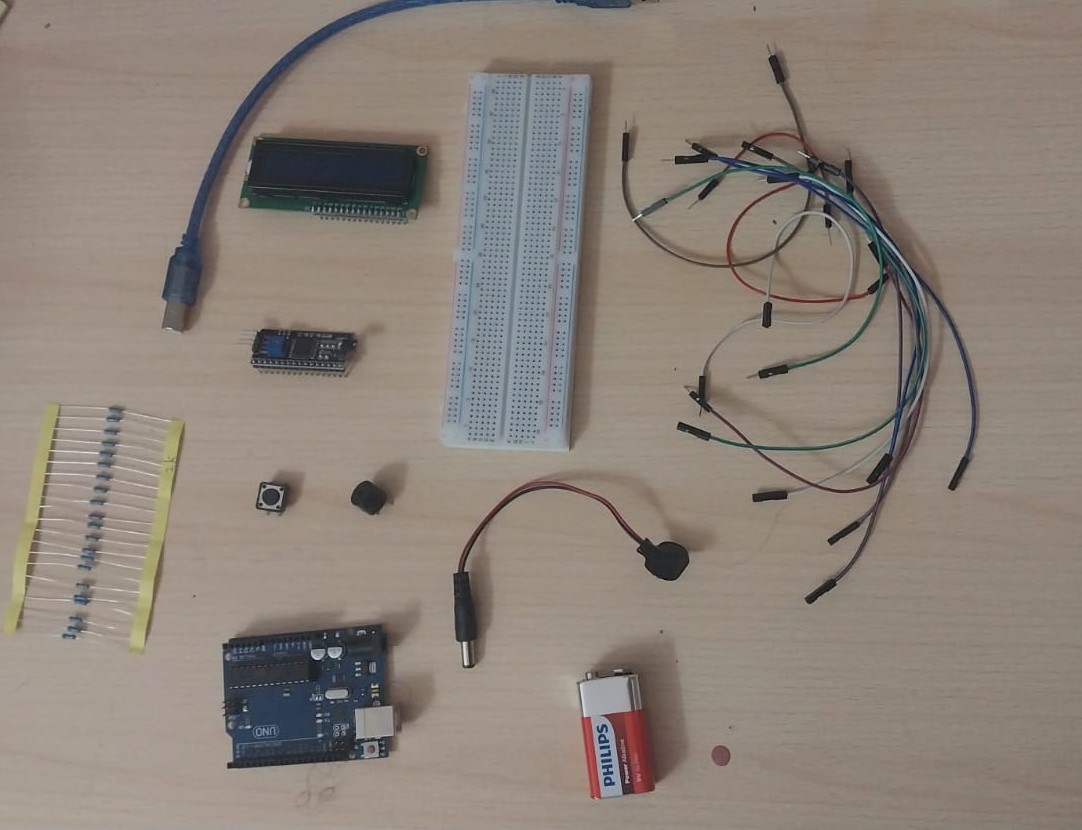
I followed the instructions in the tutorial to build and test the Dino Run game. Here is the tutorial link: Dino Run Game Tutorial
Before uploading the code, do not forget to check the microcontroller port number in Device Manager under the Ports section, then select the correct port.
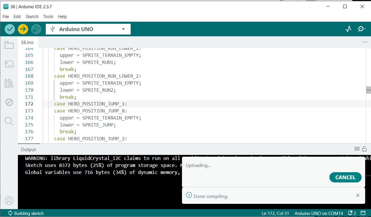
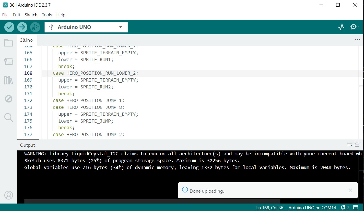
Uploading Code
To upload the code to the Arduino Uno, I connected the board to my computer using a USB cable. Then, I opened the Arduino IDE, selected the correct board type and port, and uploaded the code.
Testing
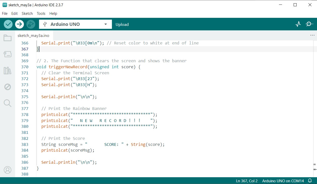
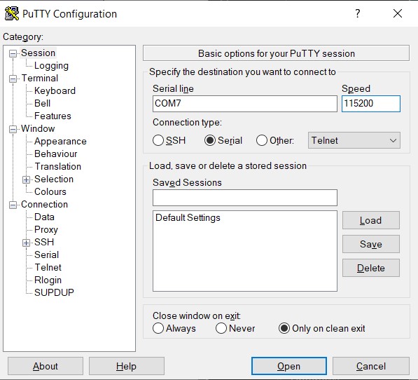
#include <LiquidCrystal_I2C.h> to #include "LiquidCrystal_I2C.h". Alternatively, you can keep it as is, but place the header file inside the Arduino IDE lib directory.Then I tried to connect the Arduino Uno to the serial monitor by editing the Dino game code. Since I wanted to show the output in color, I had to download PuTTY.
You can see the full code using this link Week 4 Dino Game Code
And you can download the code from here
B. Second Test
After I understood the hardware part, I decided it was time to write my own code.
I chose to write code for a Reaction Time Test using the Arduino Uno microcontroller. The code measures the time it takes for a user to react to a visual stimulus (an LED turning on) and displays the reaction time on the serial monitor and LCD.
Code flow:
1. Initialization Phase (Setup)
The system configures all hardware pins, starts Serial communication, and initializes the LCD. It reads the saved best reaction time from EEPROM and resets it if the value is invalid. Finally, it waits for the user to press the button before starting the game.
2. Ready & Countdown
The LCD displays “READY…”, and LEDs light up sequentially with buzzer sounds. This creates a visual and audio countdown to prepare the player.
3. Random Delay (Fairness Step)
After the countdown, the program waits for a random time between 1–4 seconds. This prevents the player from predicting when the signal will appear.
4. GO Signal & Start Timing
All LEDs turn on and a buzzer tone plays to indicate the start of the reaction test. At that exact moment, the program records the start time using millis().
5. Reaction Measurement & Record Check
When the button is pressed, the system records the end time and calculates the reaction speed. It compares the result with the stored best time and updates EEPROM if a new record is achieved.
6. Display Results & Reset
The LCD shows the current reaction time along with the best recorded time. After a short delay, the LEDs turn off and the system waits to begin a new round.
Seeed Studio XIAO ESP32C3
A. Soldering
For this assignment, I learned how to solder electronic components. Our instructor gave us a short session on how to solder electronics. Here is a helpful reference: Soldering Guide
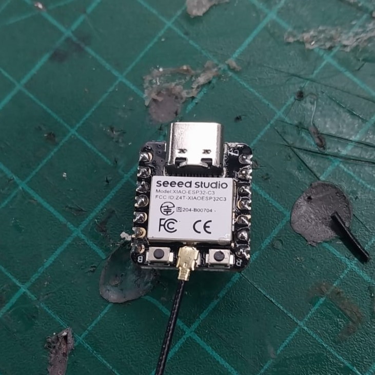
I soldered the ESP32-C3 board using a soldering iron and solder wire. I made sure to connect all the pins correctly and securely.
Before Soldering
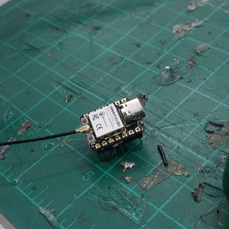
After Soldering
C. Making Arduino IDE identify the ESP32-C3
To make the Arduino IDE recognize the ESP32-C3 board, I followed these steps which I found in the getting started documentation:
- Open the Arduino IDE.
- Go to File > Preferences.
- In the "Additional Board Manager URLs" field, add the following URL:
https://jihulab.com/esp-mirror/espressif/arduino-esp32.git - Click OK to save the preferences.
- Go to Tools > Board > Boards Manager.
- Search for "ESP32" and install the "esp32" package by Espressif Systems.
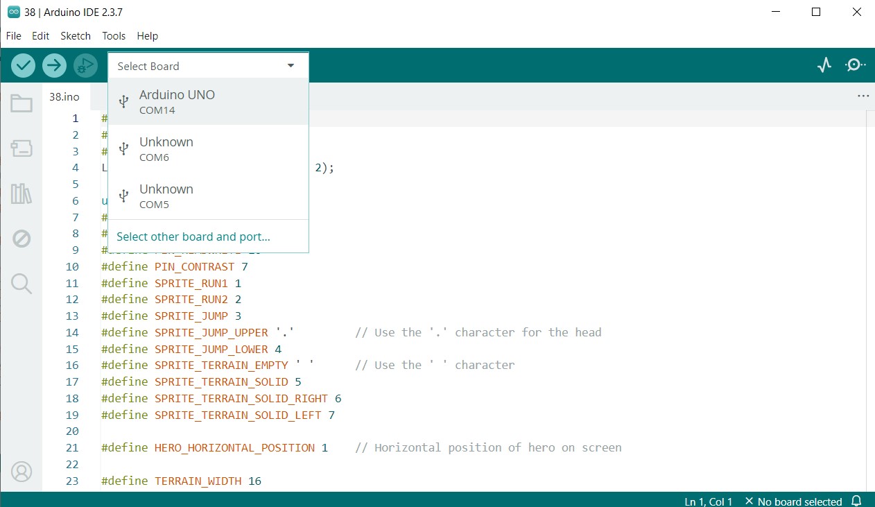
- After installation, go to Select Other Board and Ports.
- Search for ESP32C3 Dev Module, select it, choose the port connected to the board, and press OK.
- Now the Arduino IDE is ready to program the ESP32-C3 board.
💡 Note: To know which port is connected to your board, you can go to Device Manager and check which port appears and disappears when you plug and unplug the cable.
As you can see here, our port is 20.
B. Understanding GPIO
I first tried to run my code on the ESP32 board using the pin numbering shown on the board in the image below.
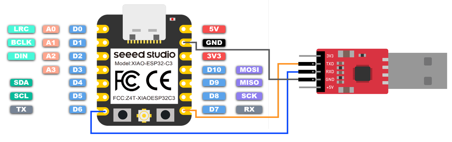
It didn’t work at first. After some research, I found the correct GPIO pins, tried them, and they worked perfectly.
Here is my conversation with ChatGPT, which helped me fully understand the GPIO mapping: View the full conversation.
You can find the ESP32 GPIO numbers in the getting started documentation.
D. Code