Week 12: Mechanical Design, Machine Design
Digital Adjustable Mannequin
You can find the full project details here.
Electrical System & Control Panel
I was responsible for the electrical part, from designing the circuit to implementing the control system.
The electrical system uses two motors and supports two operating modes: Free Mode and Preset Mode. In Free Mode, you select an axis and control it using the rotary encoder. In Preset Mode, you can choose between Small, Medium, and Large sizes, and the mannequin adjusts its dimensions accordingly. At startup, the system homes itself by rotating the motors until the limit switches are pressed.
Wiring Diagram
Here is the wiring diagram for our machine, which shows how all the components are connected together:
Components
| Main Components | Supporting Components | |
|---|---|---|
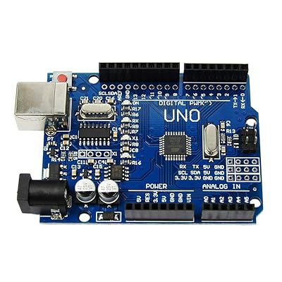
| CONTROLLER | Arduino Uno R3 | - |
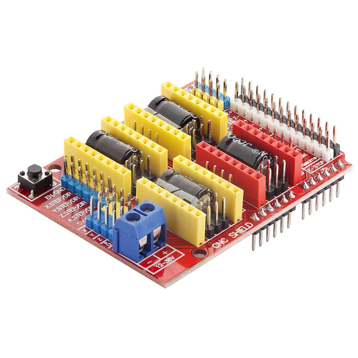
| MOTOR DRIVER | CNC Shield V3 | 2 × A4988 Drivers |
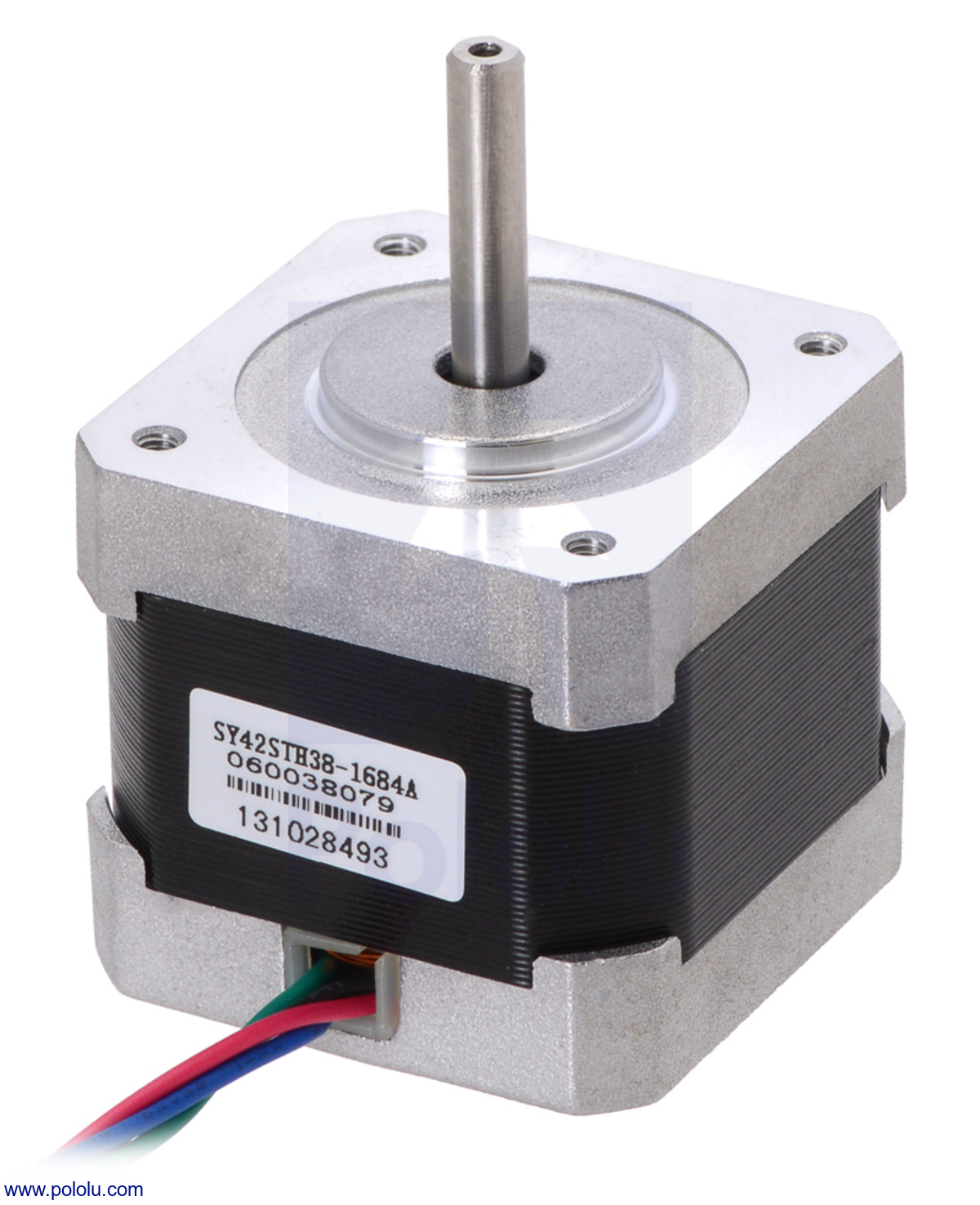
| MOTORS | 2 × NEMA 17 Stepper Motors | - |
| INPUT DEVICES | Rotary Encoder (with push button) | 4 × Push Buttons, 2 × Limit Switches |
| DISPLAY | 0.96" OLED Display (I2C) | - |
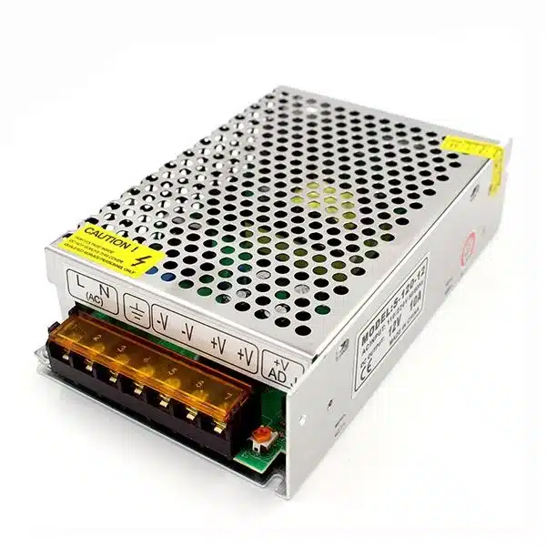
| POWER SUPPLY | 12V Power Supply (for motors) | USB / 5V for Arduino |
Component Details
- Arduino Uno R3: It serves as the brain of our machine, processing inputs and controlling outputs.
- CNC Shield V3: It interfaces the Arduino with the stepper motors, allowing precise control of their movement. The A4988 drivers on the shield regulate motor current to ensure smooth operation.
- NEMA 17 Stepper Motors: They provide the torque and precision required for the machine's movement.
- Motor Driver: It controls the stepper motors and ensures they receive the correct signals for movement.
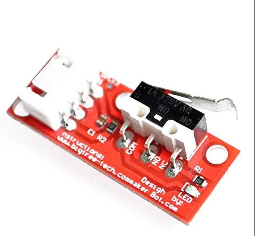
- Rotary Encoder: It allows users to input commands by rotating the knob, while the push button provides additional control functions. The limit switches define movement boundaries for safety and accuracy.
- Push Buttons and Mechanical Limit Switches: They provide additional user input options and safety features, ensuring the machine operates within defined limits.
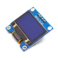
- 0.96" OLED Display: It provides real-time feedback and information to the user, improving machine interactivity.
- The 12V Power Supply ensures the motors receive sufficient power for operation, while the USB/5V connection powers the Arduino.
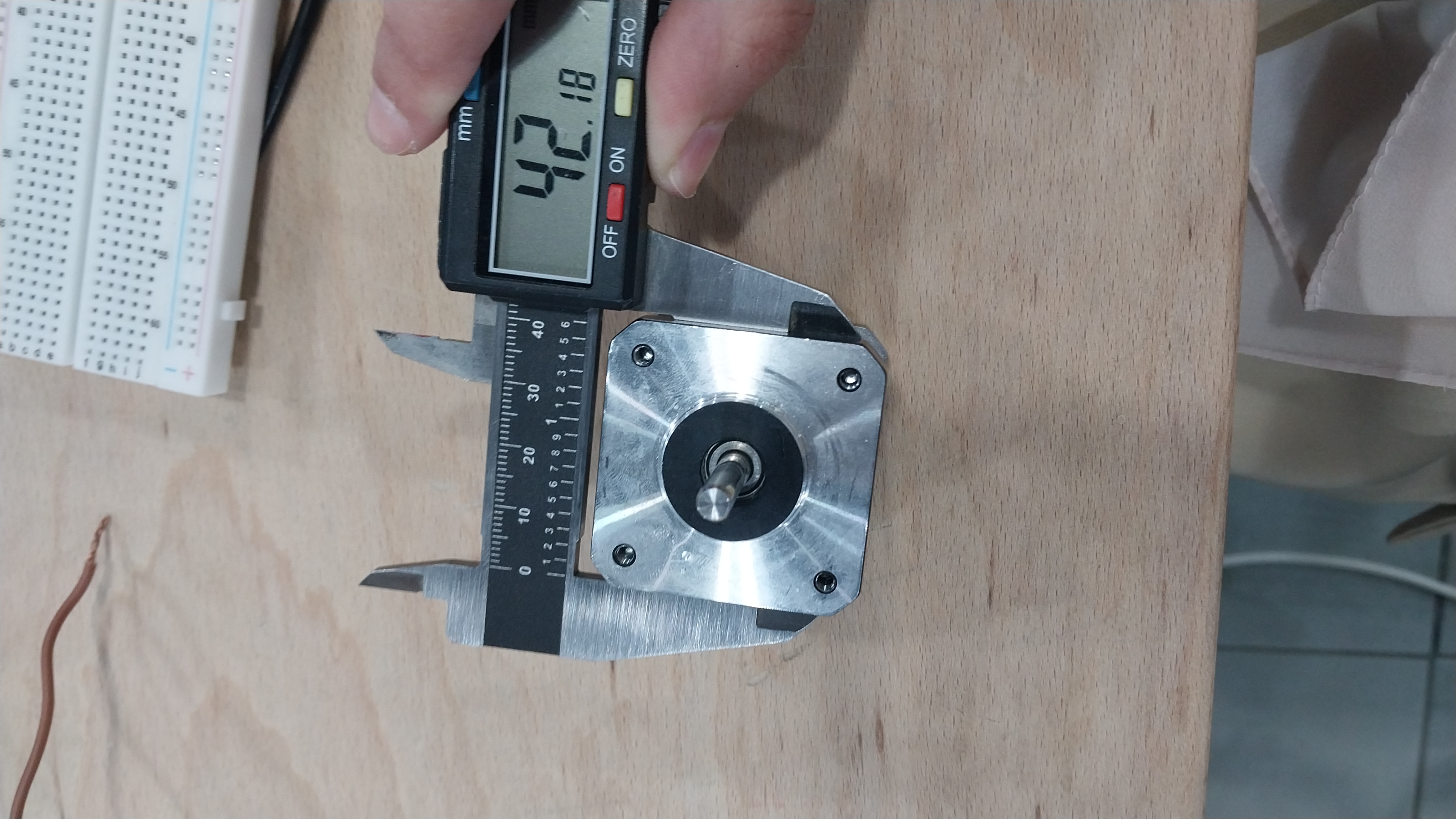
If you are not familiar with motor naming, "17" means the motor has a face width of about 1.7 inches (42 mm), as shown in the images below. To learn more, see this reference: Pololu NEMA 17 Stepper Motor
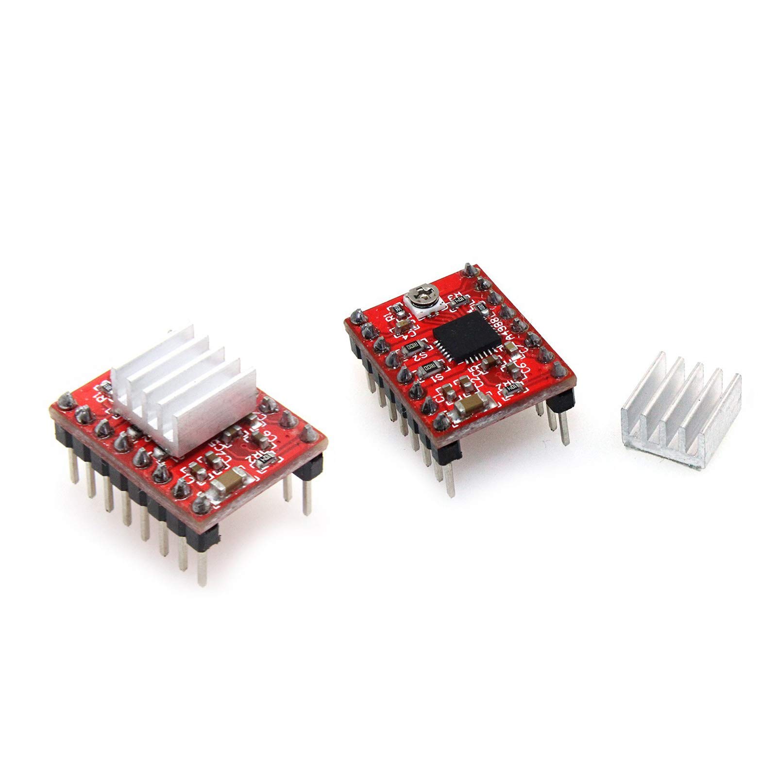
We used the A4988 motor driver.
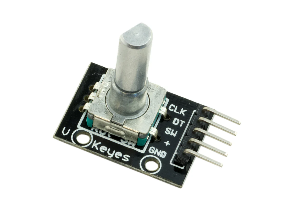
I chose this encoder because when I tried using a potentiometer, the signal was analog and harder to control. For our digital system, the rotary encoder was a better option.
If you want to learn more about rotary encoders and how they work, here is a useful reference: Rotary Encoder: A Comprehensive Guide to Understanding and Using Them
Testing & Understanding Components
At this stage, I focused on testing and understanding how motors and drivers work together, since this was my first time working with them.
First, I connected the motor driver to a breadboard and made the connections myself without the CNC shield so I could better understand how it works.
I followed this reference to learn how to connect the motor driver and control the motor: How to control a stepper motor with DRV8825 driver and Arduino
Here are some useful images from the reference:
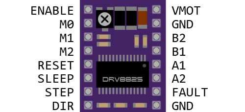
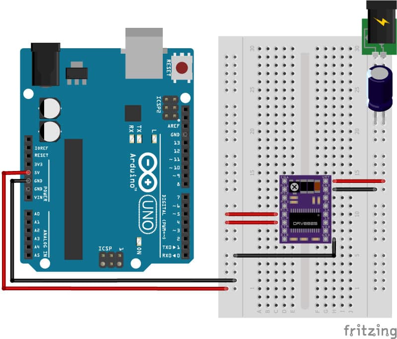
💡 Note: In this test, I used the DRV8825 motor driver instead of the A4988 because I did not have an A4988 at the time. They are very similar, and the concept is the same.
As mentioned in the reference, it is important to adjust the motor driver's current setting for optimal performance; otherwise, the motor may overheat or not function properly.
You can use this reference to find the suitable current setting for your motor.
To adjust the current setting, you can use the potentiometer on the motor driver and turn it until you achieve the desired current.
Each driver has a different method for calculating the desired current by measuring voltage with a multimeter, as shown in the figure below:
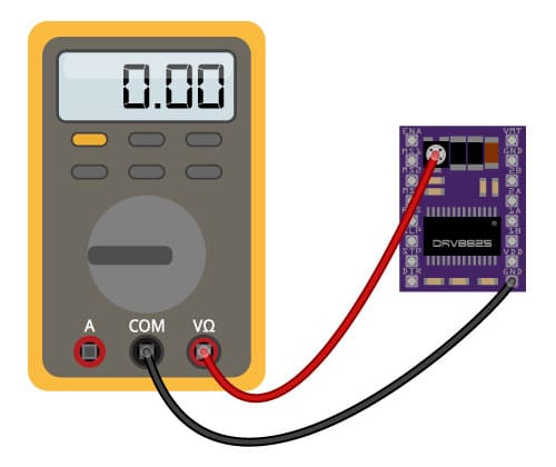
💡 Note: Here is a reference for the A4988 motor driver, which is the one we used in our project: How to control a stepper motor with A4988 driver and Arduino
Building Circuit
Free Mode
I started by implementing one mode: the free mode, using the CNC shield with push buttons and a rotary encoder.
In the video, you can see that I am controlling the motor using the push buttons, and I have set up the limit switches to stop the motor when it reaches its limits. This allows for safe operation and prevents damage to the machine.
You can download the code from here.
In the next step, I will add the OLED display to enhance the user interface.
In this video, you can see the OLED display showing the selected axis, which provides real-time feedback to the user and enhances the interactivity of the machine.
You can download the code from here.
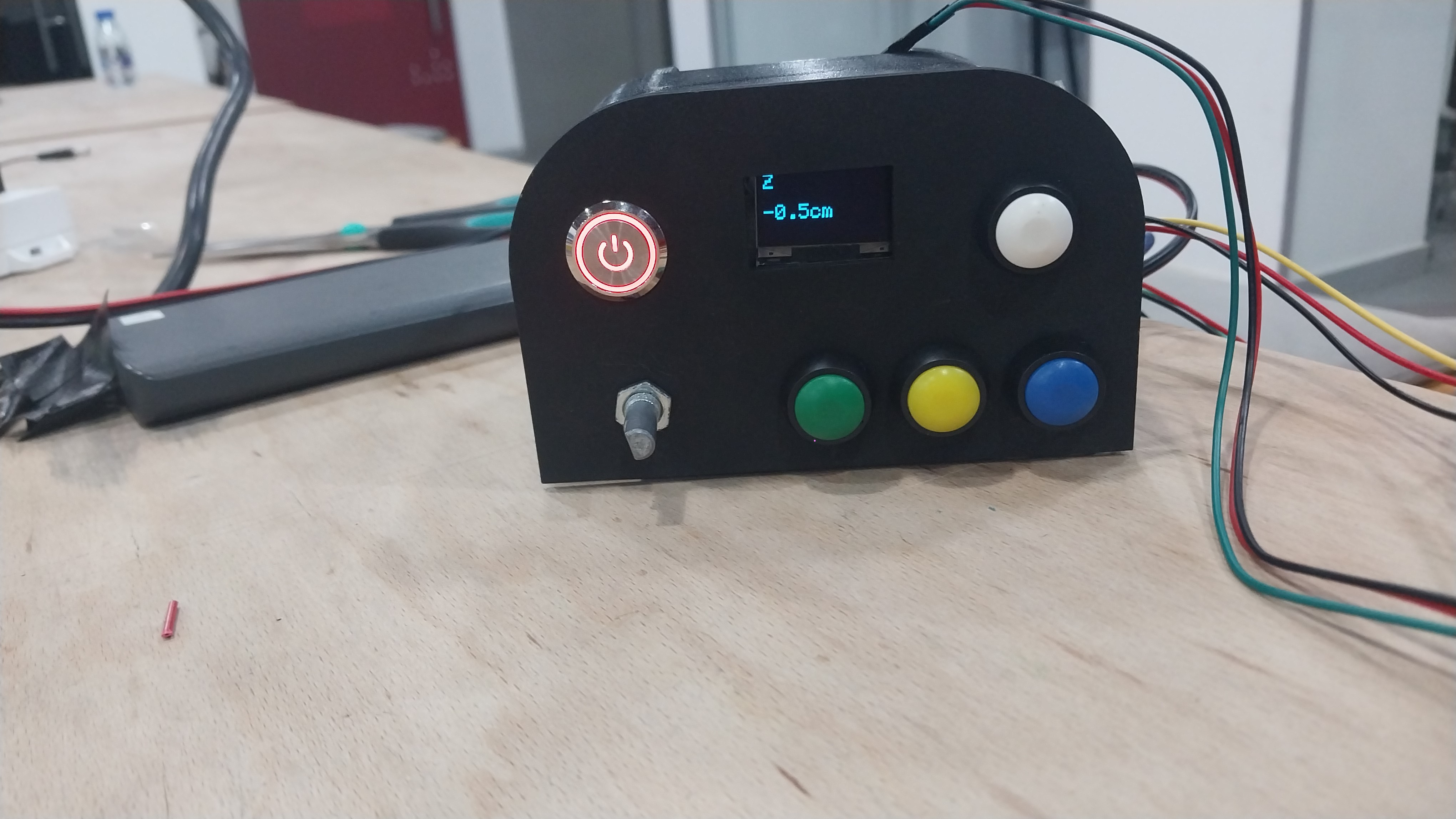
Control Panel
I designed a control panel to make user interaction easier. It includes buttons for selecting the mode and axis, a rotary encoder for adjusting dimensions, and an OLED display for feedback.
The control panel is user-friendly and intuitive, allowing users to navigate the machine's modes and settings easily.
Components
The control panel consists of the following components:
- Push Buttons: used for selecting the mode (free or preset) and for selecting the axis (X, Y, Z).
- Power Button: used to turn the machine on and off.
- Rotary Encoder & OLED Display: used for adjusting dimensions and providing real-time feedback; these are the same components shown in the videos above.
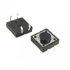
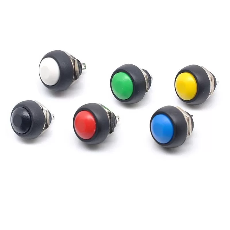
I used a 2-pin mini switch (1A, 12V): a waterproof PBS33B momentary, non-locking push button, as shown in the image below.
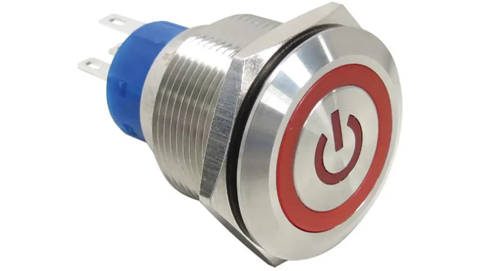
I used a 12V 16mm metal push-button switch with LED momentary reset.
Design:
I designed the control panel using Fusion 360, laser-cut the front part from wood, and 3D-printed the back part to hold the components in place. The design allows easy access to the buttons and display while keeping the wiring organized and secure.
You can download the design file from here.
Soldering:
After assembling the control panel, I soldered the components to ensure secure and reliable connections. Soldering is an essential step in building electronic circuits because it creates strong bonds between components and helps prevent loose connections that can cause malfunctions.
I made sure to solder all connections properly to ensure a reliable circuit and reduce wire clutter.
Testing the First Mode
After completing the control panel, I tested the first mode to ensure everything was working correctly. This involved connecting the panel to the Arduino and verifying that the buttons and rotary encoder functioned as intended.
Add Second Mode & Integrate
After successfully testing the first mode, I added the second mode (Preset Mode) and integrated it with the control panel. This involved programming the Arduino to recognize different modes and respond to user input from the buttons and rotary encoder.
The second mode provides a preset option for users to quickly select from predefined sizes S, M and L.
You can download the code from here.
Final Testing
Finally, I conducted a comprehensive test of the machine to ensure all components worked together seamlessly. This included testing both modes (Free and Preset) to verify correct responses to user input and smooth motor operation.