Week 9: Input Devices
Group Assignment
This week our group assignment focuses on understanding input sensors, interpreting digital vs. analog signals, and utilizing test equipment to observe real-time sensor waveforms communicating with an MCU.
You can find the full documentation: Group Assignment Documentation
Individual Assignment
For this week, I tested different input devices and compared them to the final project requirements.
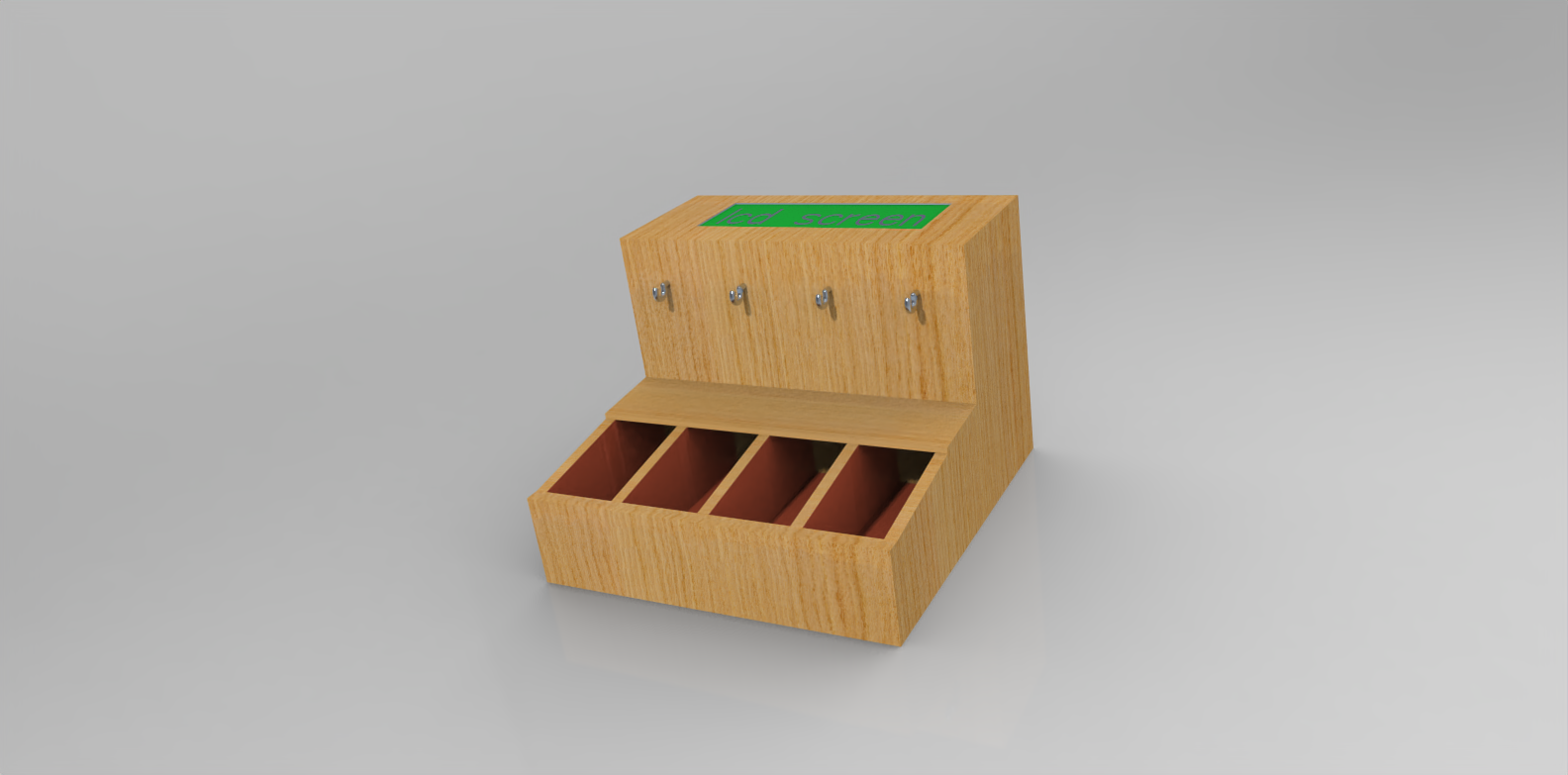
The input devices I tested are focused on detecting if there is an object in the slots.
Initially, I considered three sensors to achieve that:
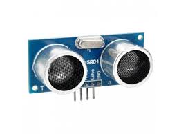
- Ultrasonic sensor
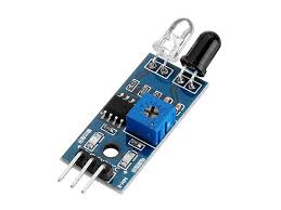
- Infrared sensor
- Strain gauge
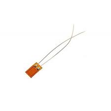
However, before testing, I eliminated the strain gauge because experts and potential buyers advised me that I must ensure the item is perfectly positioned on the strain gauge. Additionally, I need specific types that can detect light objects, since the items in the slots could have varying weights.
PCB
I used the PCB from the previous week's assignment.
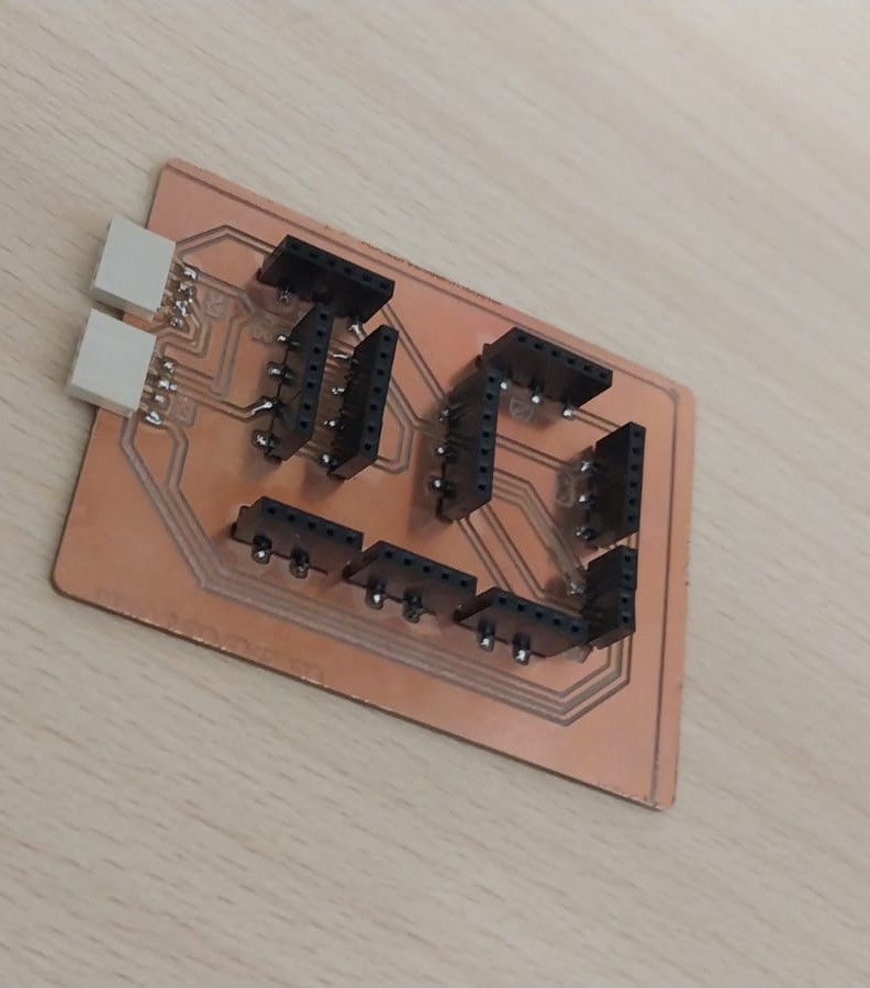
You can see the full production documentation here.
Slot Sample
Design Process:
To make sure that I pick the correct sensor for my final project, I designed a sample slot in the specific dimensions that I want so I could test the sensors on it.
Here is the design process using Fusion 360:
Here is the Fusion 360 file to download.
And here is the 3D design:
which you can download from here.
Cutting Process:
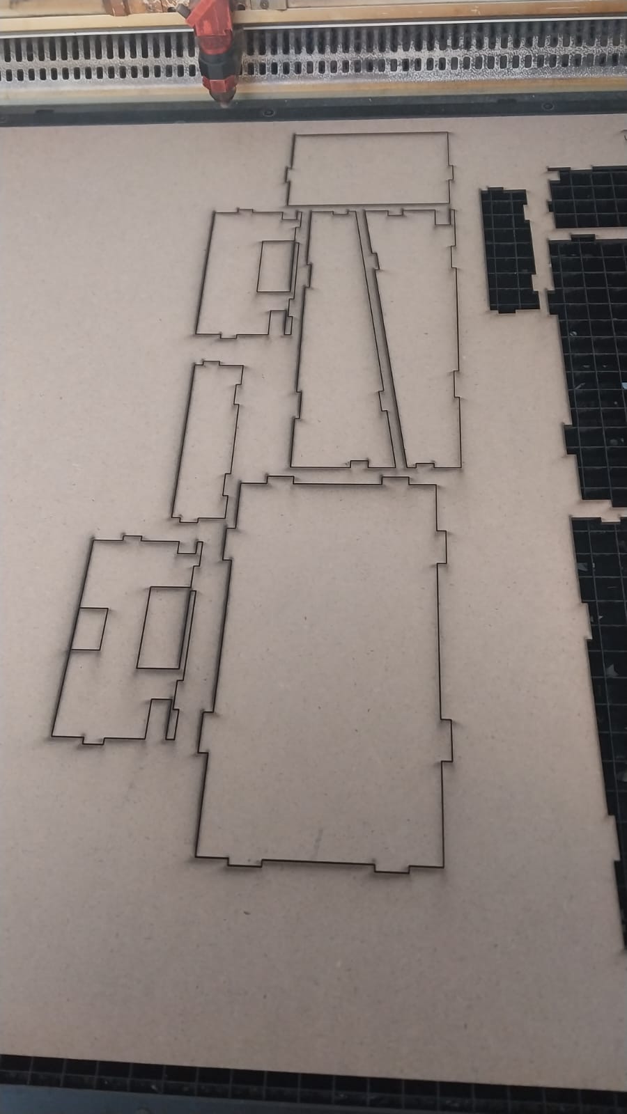
I cut the slot sample using the laser cutter, and here is the cutting process:
And here is the part after cutting:
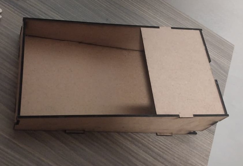
And here is the final result:
- Interfacing IR Sensor Module with Arduino
- Interfacing Ultrasonic Sensor with Arduino Uno
- How to Interface Arduino with an Ultrasonic Sensor?
- Ultrasonic vs IR sensors for proximity detection with Arduino servo motor robotics
- IR Sensor
- Strengths: Small size, easy to integrate into the project, and suitable for short-range detection.
- Weaknesses: Less accurate, affected by ambient light, and struggles to detect dark or black objects. It also has a limited and less reliable detection range. Additionally, its detection range cannot be controlled through code and can only be adjusted using a potentiometer. It does not provide exact distance measurements, only simple detection (object detected or not).
- Ultrasonic Sensor
- Strengths: More accurate, not affected by light, and capable of detecting a wider range of distances. It provides actual distance measurements and allows flexible control through code, where specific actions can be triggered at certain distance thresholds, making it more suitable for the project.
- Weaknesses: Larger in size, has a slower response time compared to the IR sensor, and can be affected by soft materials that absorb sound waves.
Testing the sensors:
Before testing the sensors, I looked into some theory about sensors. Here are two good resources:
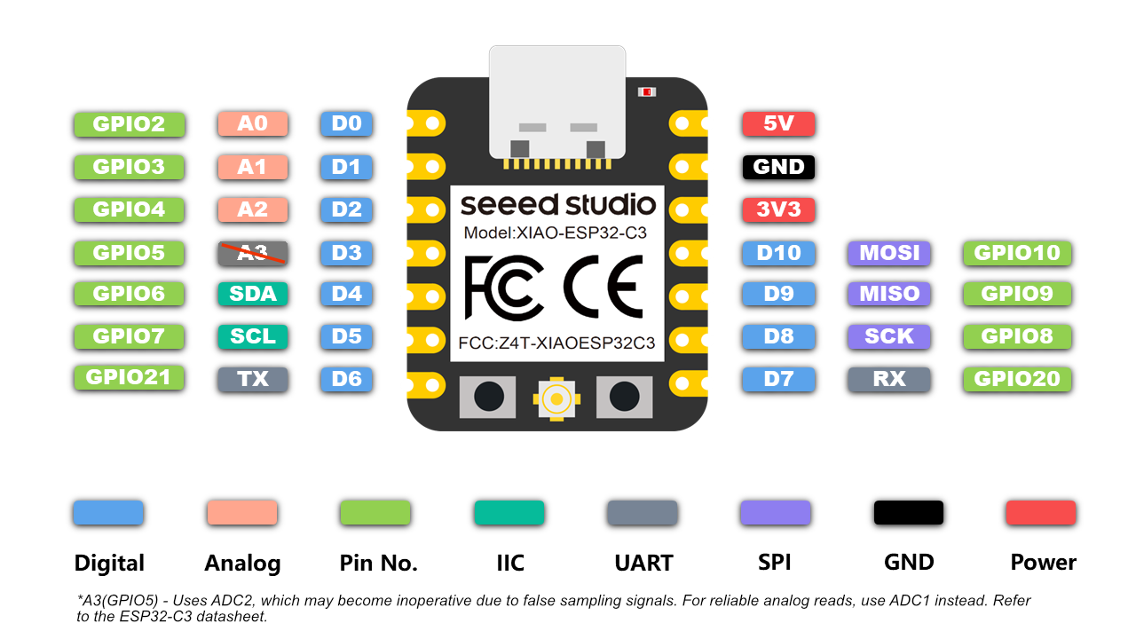
All the tests in this document are conducted using Xiao Seeed ESP32-C3 board. So Don't forget to use GPIO .
All the codes compiled using Arduino IDE.
Testing the IR sensor:
First, I tested the IR sensor using Arduino to make sure I understood the concept and learned how to use it. I referenced Interfacing IR Sensor Module with Arduino, which I mentioned earlier.
Here is the PCB connection:
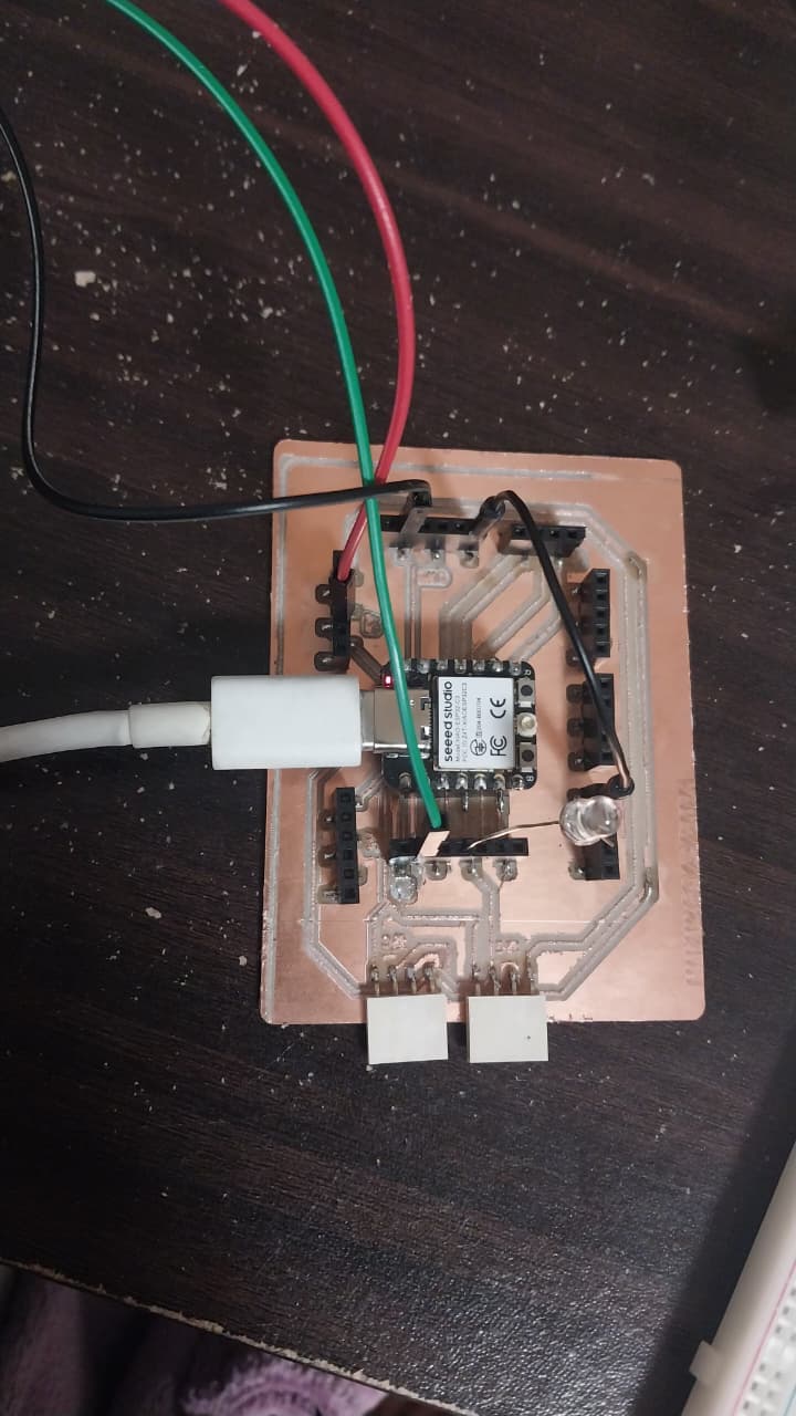
You can see the full code using this link: IR Sensor Arduino Code and download it from here.
Then, I tested the IR sensor with a Xiao Seeed ESP32-C3 board using my PCB.
IR Sensor Code:
Here is the code I used to test the IR sensor with xiao seeed ESP32-C3:
// IR Sensor Code for Xiao Seeed
    // IR Sensor Testing Code
int IRSensor = 9;
int LED = 3;
void setup(){
  Serial.begin(115200);
  Serial.println("Serial Working");
  pinMode(IRSensor, INPUT);
  pinMode(LED, OUTPUT);
}
void loop(){
  int sensorStatus = digitalRead(IRSensor);
  if (sensorStatus == 1)
  {
    digitalWrite(LED, LOW);
    Serial.println("Motion Detected!");
  }
  else  {
    digitalWrite(LED, HIGH);
    Serial.println("Motion Ended!");
  }
}
IR Sensor Code Explanation:the code reads the status of the IR sensor and controls an LED based on whether motion is detected, so if the sensor detects motion, the LED will turn off, and if no motion is detected, the LED will turn on.
Testing the Ultrasonic sensor:
First, I tested the Ultrasonic sensor using Arduino to make sure I understood the concept and learned how to use it. I referenced Interfacing Ultrasonic Sensor with Arduino, which I mentioned earlier.
Here is the physical testing connection:
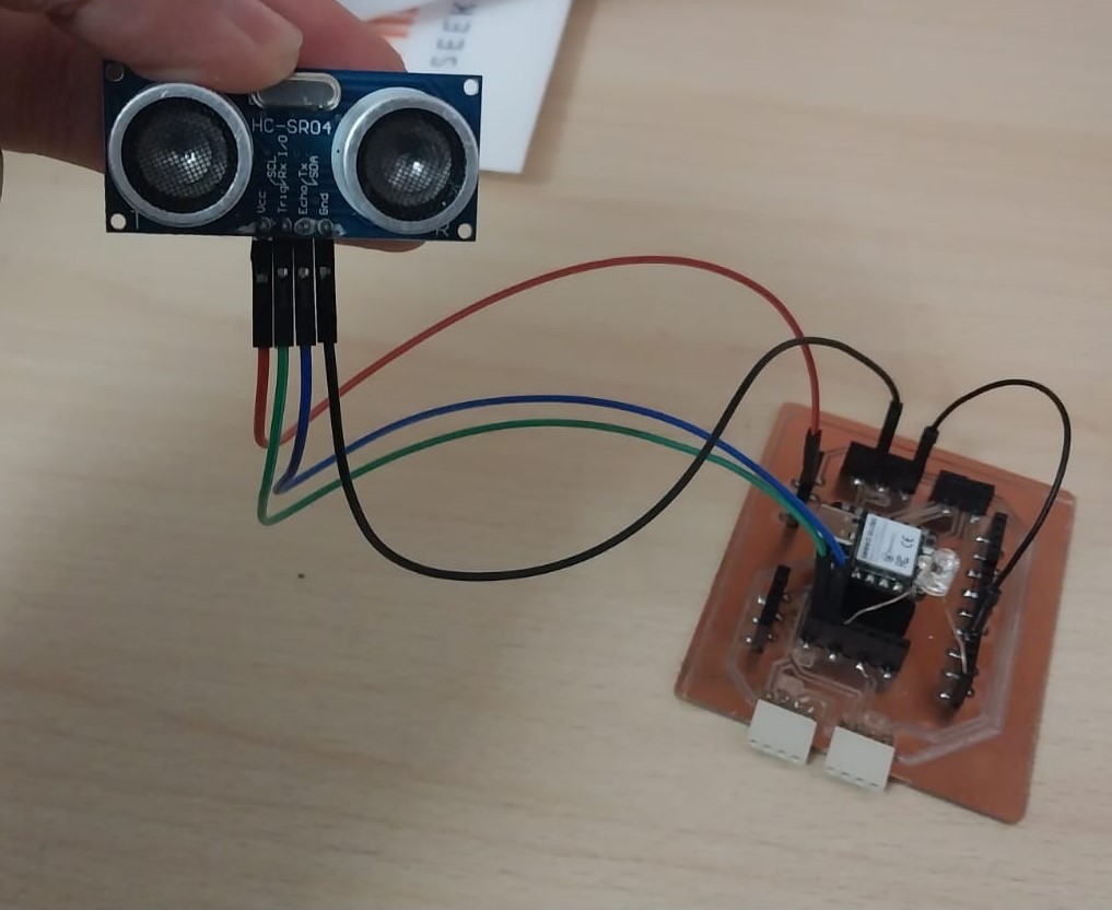
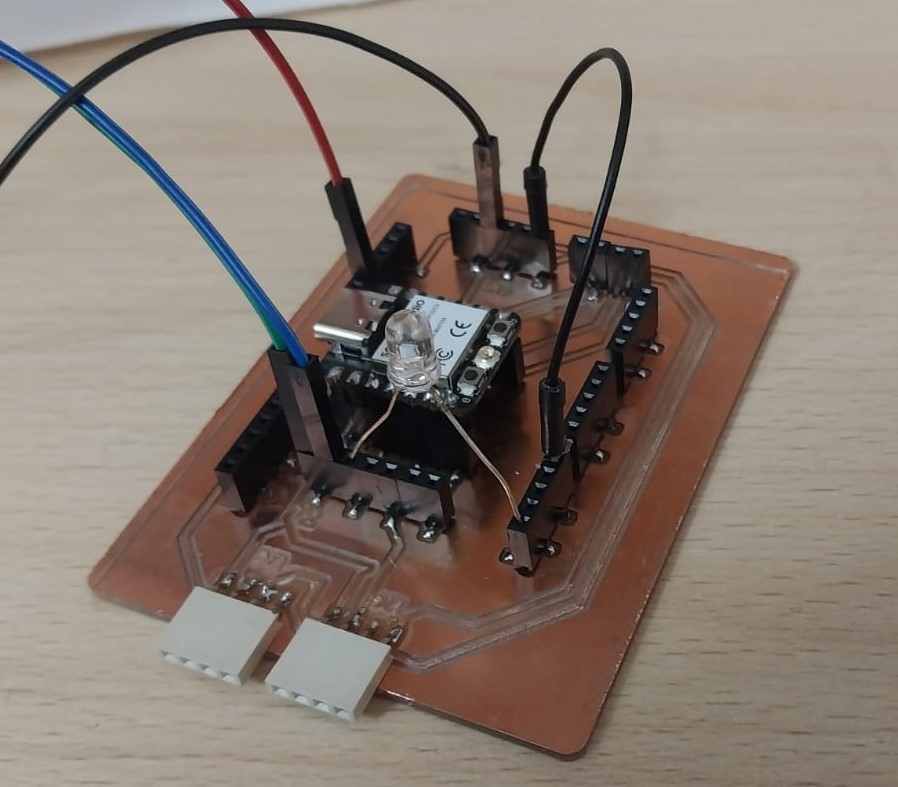
Here is the connection diagram using Wokwi:
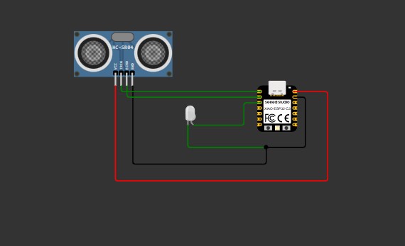
Ultrasonic Sensor Code:
Here is the code I used to test the Ultrasonic sensor with xiao seeed ESP32-C3:
// Ultrasonic Sensor Code for Xiao Seeed ESP32-C3
#define TRIG_PIN 2
#define ECHO_PIN 3
#define LED_PIN 4

long duration;
float cm, inches;

void setup() {
  Serial.begin(115200); // ESP32 usually uses higher baud

  pinMode(TRIG_PIN, OUTPUT);
  pinMode(ECHO_PIN, INPUT);
  pinMode(LED_PIN, OUTPUT);
}

void loop() {
  // Clean trigger
  digitalWrite(TRIG_PIN, LOW);
  delayMicroseconds(5);

  // Send pulse
  digitalWrite(TRIG_PIN, HIGH);
  delayMicroseconds(10);
  digitalWrite(TRIG_PIN, LOW);

  // Read echo
  duration = pulseIn(ECHO_PIN, HIGH);

  // Convert to distance
  cm = (duration / 2.0) / 29.1;
  inches = (duration / 2.0) / 74.0;

  // LED control
  if (cm < 18) {
    digitalWrite(LED_PIN, HIGH);
  } else {
    digitalWrite(LED_PIN, LOW);
  }

  // Print
  Serial.print(inches);
  Serial.print(" in, ");
  Serial.print(cm);
  Serial.print(" cm");
  Serial.println();

  delay(250);
}
Ultrasonic Sensor Code Explanation:the code measures the distance to an object using an ultrasonic sensor and controls an LED based on that distance. If the object is closer than 18 cm, the LED turns on; otherwise, it remains off. The measured distance is printed to the serial monitor in both inches and centimeters.
Simulation:
Before I upload the code to the board, I simulated the behavior using Wokwi.
You could see the simulation from here.
Testing on the board:
After simulating the code, I uploaded it to the board and tested the sensor.
Comparison:
After testing both sensors, each has its own strengths and weaknesses:
Conclusion:
Based on testing and analysis, the Ultrasonic Sensor is more suitable for my final project due to its higher accuracy, wider detection range, and ability to measure exact distances. It also provides better control through code, allowing me to trigger actions at specific distances. Although it has a slower response time compared to the IR sensor, this does not significantly affect the performance of my application. Additionally, while it may not perform well with sound-absorbing materials, this limitation does not impact my use case.