Week 10: Output Devices
In this week, we will be working on output devices, from their power consumption to testing. This week's assignment will focus on the output device testing for the final project, which you can see details about in the final project page.
Group Assignment
For the group assignment, we were asked to measure the power consumption of an output device. Our group decided to measure the power consumption of LCD and OLED screens and compare them.
Here is the full documentation: Group Assignment Documentation
Individual Assignment
For the individual assignment, I focused on output device testing for the final project. I will be using an Ultrasonic sensor to detect the distance between the user and the device and then display it on a screen with light indication using neopixel.
PCB
I used the PCB from the previous week's assignment.
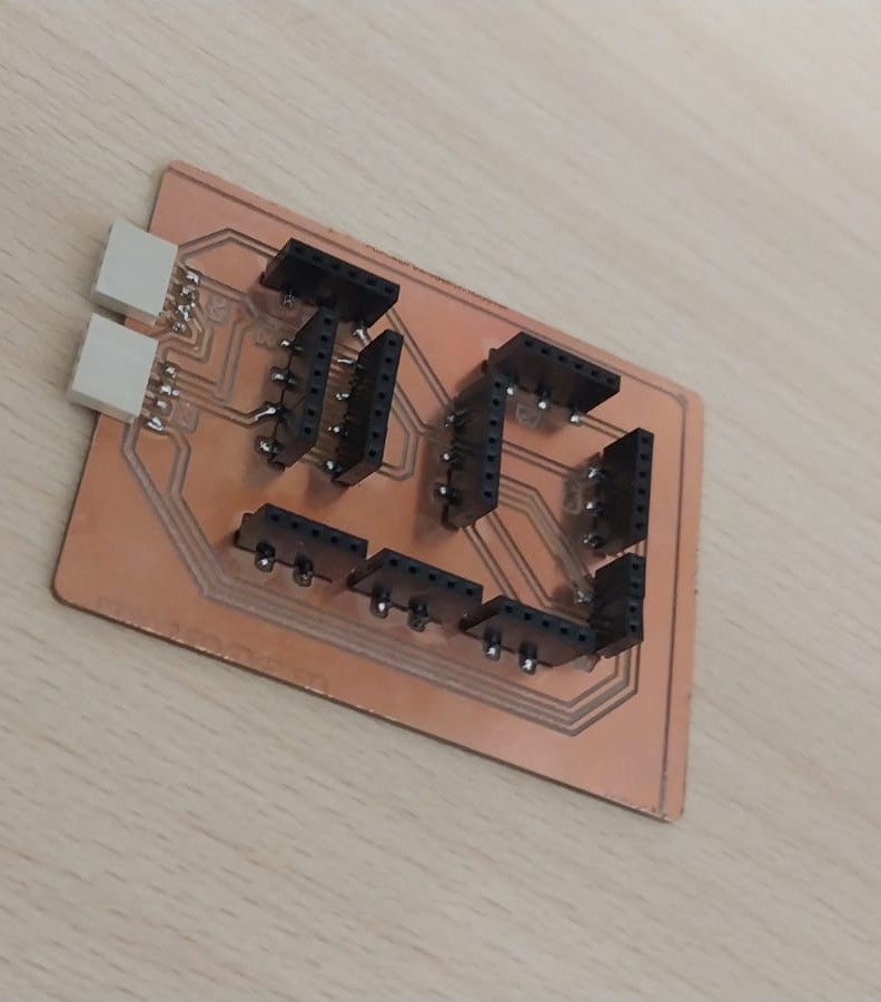
You can see the full production documentation here.
Slot Sample
Design Process:
To ensure I pick the correct sensor for my final project, I designed a sample slot with the specific dimensions I want so I could test the sensors on it.
Here is the design process using Fusion 360:
Here is the Fusion 360 file to download.
And here is the 3D design:
which you can download from here.
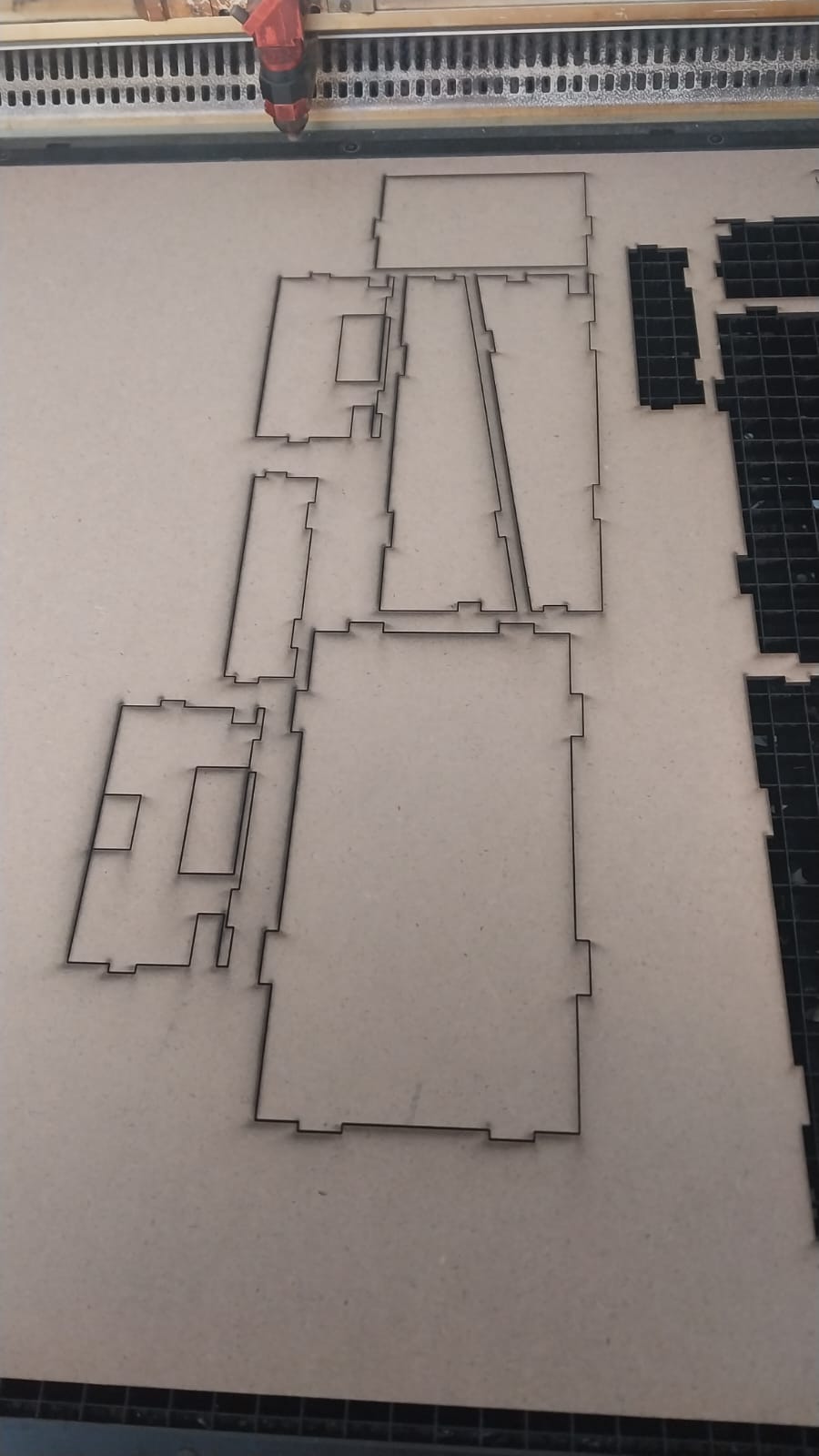
Cutting Process:
I cut the slot sample using the laser cutter, and here is the cutting process:
And here is the part after cutting:
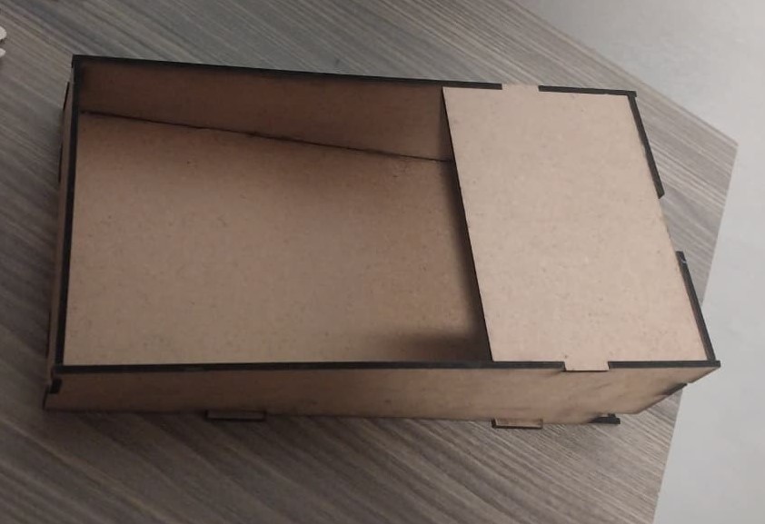
And here is the final result:
Output Devices
- Neopixel LEDs.
- LCD Display.
- OLED Display.
Before proceeding to connection and testing, here are useful resources that helped me understand the concepts:
- Neopixels, How Do They Work?
- How to Use I2C LCD with ESP32 on Arduino IDE
- Guide for I2C OLED Display with Arduino
- OLED vs LCD: Which Is Easier to Interface with Arduino?
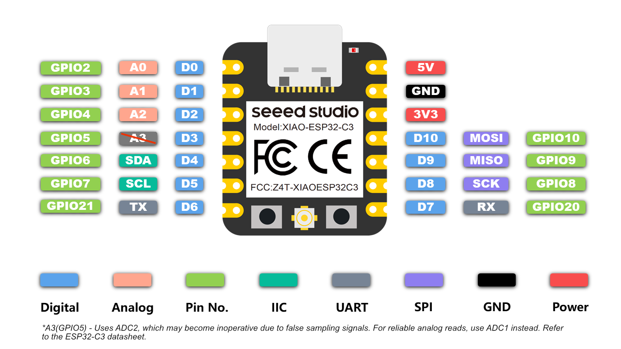
All the tests in this document are conducted using the Xiao Seeed ESP32-C3 board. Don't forget to use GPIO.
And here is the connection and testing process:
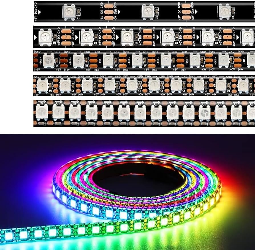
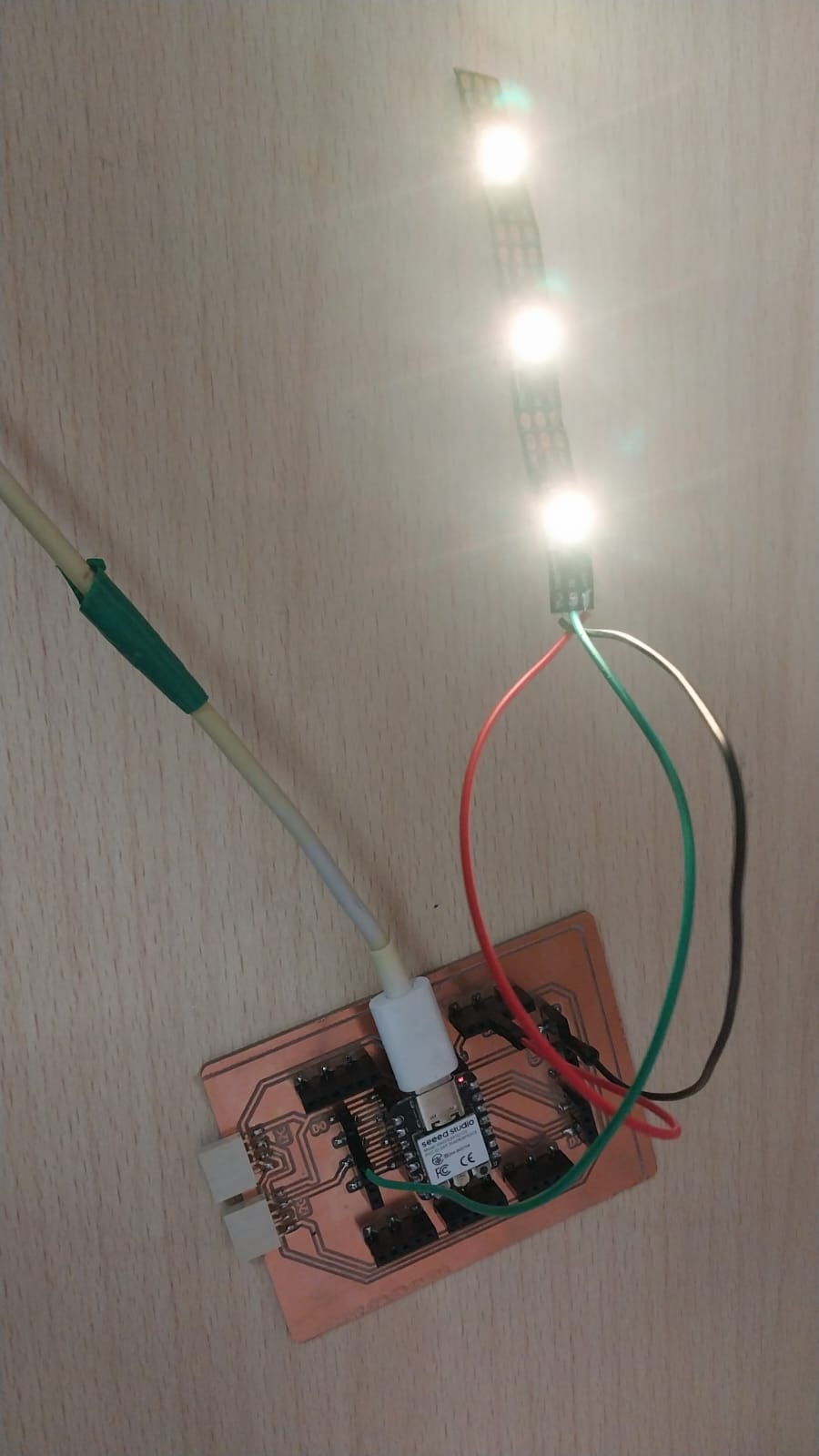
Neopixel LEDs:
Neopixel LEDs are a type of programmable LED that can display a wide range of colors and effects, allowing you to connect multiple LEDs in series and control them using one pin.
To connect and test neopixel LEDs, I first had to read the documentation Neopixels, How Do They Work?.
Connection:
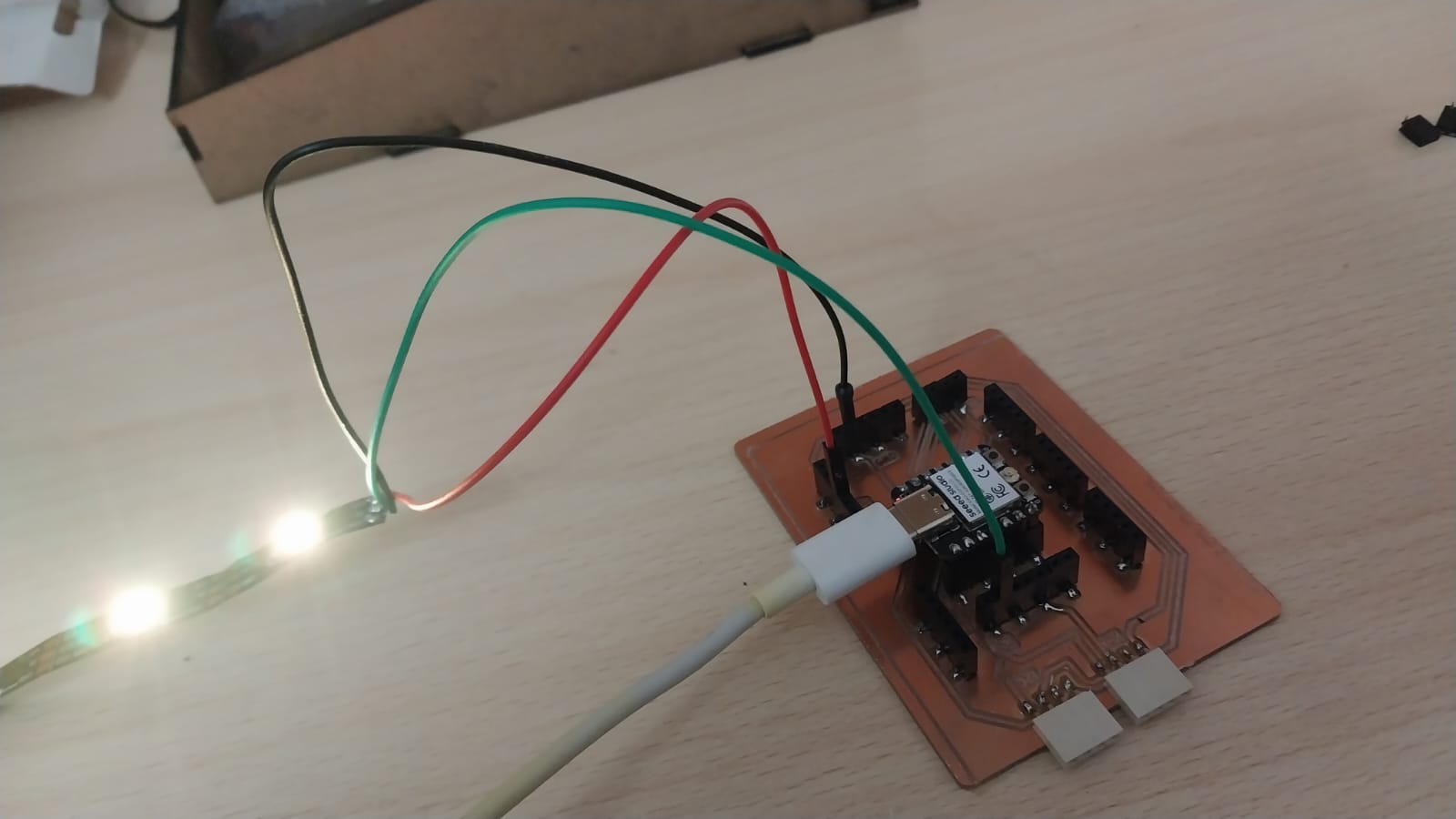
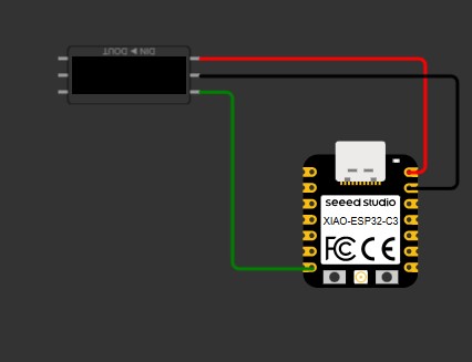
To connect the neopixel LEDs, I used the following connections:
- Connect the data input pin of the first LED to a digital pin on the microcontroller (e.g., pin 1).
- Connect the power (VCC) and ground (GND) pins of the LEDs to the appropriate power source (e.g., 5V and GND).
Here is the connection diagram using Wokwi.
Code:
To test the neopixel LEDs, I used the following code:
              #include  <Adafruit_NeoPixel.h>

#define PIN        2
#define NUMPIXELS  3

Adafruit_NeoPixel pixels(NUMPIXELS, PIN, NEO_GRB + NEO_KHZ800);

void setup() {
  pixels.begin();
  pixels.setBrightness(50); // Lower brightness helps see the individual LEDs better
}

void loop() {
    pixels.setPixelColor(0, pixels.Color(0, 250, 0));

  // LED 1: Bright Red
  pixels.setPixelColor(1, pixels.Color(255, 0, 0));

  // LED 2: Bright Green
  pixels.setPixelColor(2, pixels.Color(0, 0, 255));

  pixels.show();
  delay(1000);
}
This code initializes the neopixel strip, sets the brightness, and then in the loop, it sets the colors of three LEDs (green, red, and blue) and updates the strip to show the changes.
You can download the code from here.
And here is the testing process:
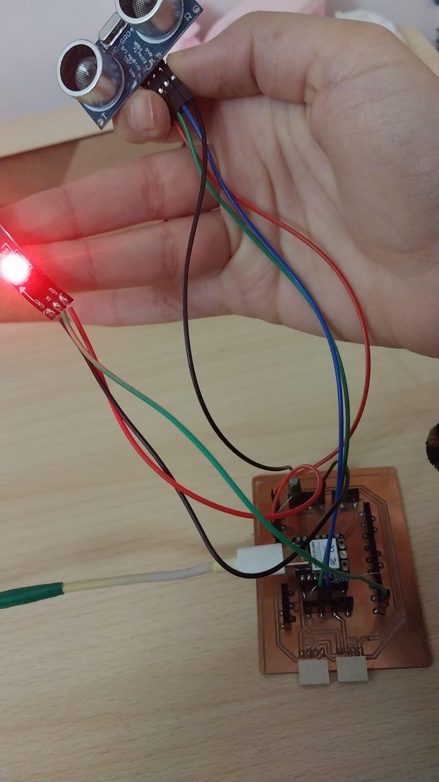
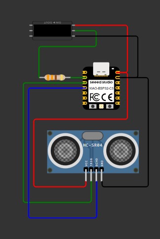
Integrate with Ultrasonic
- Connection:
- Code:
OLED:
LCD & OLED:
Here is the connection diagram:
                #define TRIG_PIN 4
#define ECHO_PIN

long duration;
float cm, inches;
#include  <Adafruit_NeoPixel.h>
#ifdef __AVR__
 #include  <avr/power.h> // Required for 16 MHz Adafruit Trinket
#endif

// Which pin on the Arduino is connected to the NeoPixels?
#define PIN        3 // On Trinket or Gemma, suggest changing this to 1

// How many NeoPixels are attached to the Arduino?
#define NUMPIXELS 3 // Popular NeoPixel ring size

// When setting up the NeoPixel library, we tell it how many pixels,
// and which pin to use to send signals. Note that for older NeoPixel
// strips you might need to change the third parameter -- see the
// strandtest example for more information on possible values.
Adafruit_NeoPixel pixels(NUMPIXELS, PIN, NEO_GRB + NEO_KHZ800);

#define DELAYVAL 500 // Time (in milliseconds) to pause between pixels

void setup() {
  Serial.begin(115200); // ESP32 usually uses higher baud

  pinMode(TRIG_PIN, OUTPUT);
  pinMode(ECHO_PIN, INPUT);
#if defined(__AVR_ATtiny85__) && (F_CPU == 16000000)
  clock_prescale_set(clock_div_1);
#endif


  pixels.begin(); // INITIALIZE NeoPixel strip object (REQUIRED)
}

void loop() {
  // Clean trigger
  digitalWrite(TRIG_PIN, LOW);
  delayMicroseconds(5);

  // Send pulse
  digitalWrite(TRIG_PIN, HIGH);
  delayMicroseconds(10);
  digitalWrite(TRIG_PIN, LOW);

  // Read echo
  duration = pulseIn(ECHO_PIN, HIGH);

  // Convert to distance
  cm = (duration / 2.0) / 29.1;
  inches = (duration / 2.0) / 74.0;
pixels.clear();
  // LED control
  if (cm < 18) {
     pixels.setPixelColor(0, pixels.Color(0,255, 0));

    pixels.show();   // Send the updated pixel colors to the hardware.
  } else {
         pixels.setPixelColor(0, pixels.Color(255,0, 0));

    pixels.show();
  }

  // Print
  Serial.print(inches);
  Serial.print(" in, ");
  Serial.print(cm);
  Serial.print(" cm");
  Serial.println();

  delay(50);
}
This code initializes the ultrasonic sensor and the neopixel strip. It continuously measures the distance using the ultrasonic sensor and updates the color of the first LED on the neopixel strip based on the distance (green if less than 18 cm, red otherwise).
You can download the code from here.
And here is the testing process:
Next, I will test the LCD and OLED displays to compare them and select one for my final project.
Before proceeding to the testing step, I recommend reading more about the differences between OLED and LCD. Here is a good reference: OLED vs LCD: Which Is Easier to Interface with Arduino?
Before testing OLED, read this guide, which really helped me during the testing process: Guide for I2C OLED Display with Arduino
For this test I am using an SSD1306-based OLED display with 0.96 inches.
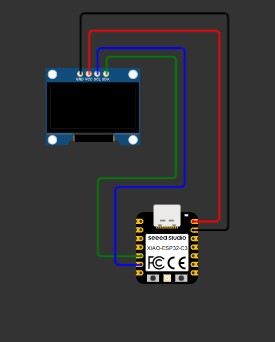
Connection:
To connect the OLED display, I used the following connections:
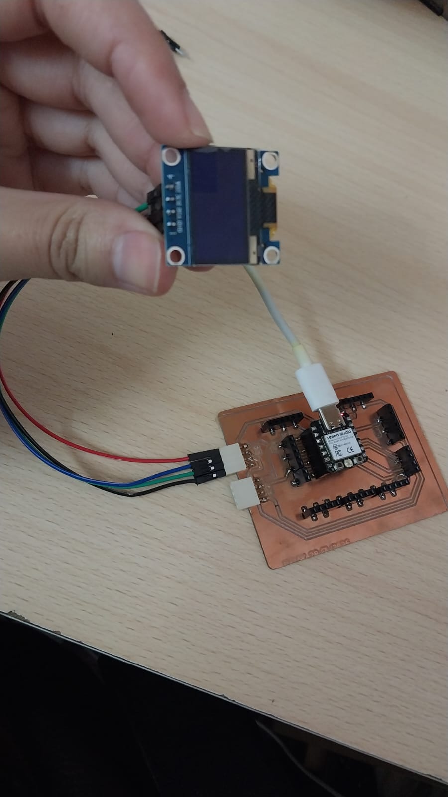
Here is the connection diagram using Wokwi.
Code:
#include#include <Adafruit_GFX.h> #include <Adafruit_SSD1306.h> #define SCREEN_WIDTH 128 #define SCREEN_HEIGHT 64 Adafruit_SSD1306 display(SCREEN_WIDTH, SCREEN_HEIGHT, &Wire, -1); int x = 0; // position of text void setup() { Wire.begin(6, 7); display.begin(SSD1306_SWITCHCAPVCC, 0x3C); } void loop() { display.clearDisplay(); display.setTextSize(2); display.setTextColor(SSD1306_WHITE); display.setCursor(x, 20); // 👈 move here display.println("Hello"); display.display(); x += 2; // move right if (x > 128) { // reset when off screen x = -50; } delay(50); // speed control } This code initializes the OLED display and continuously moves the text "Hello" across the screen from left to right. The text resets to the left side once it goes off the right edge of the display.
You can download the code from here.
And here is the testing process:
Since I had worked with LCD previously, I decided to test the same display type in both LCD and OLED to see the differences between them and choose the best one.
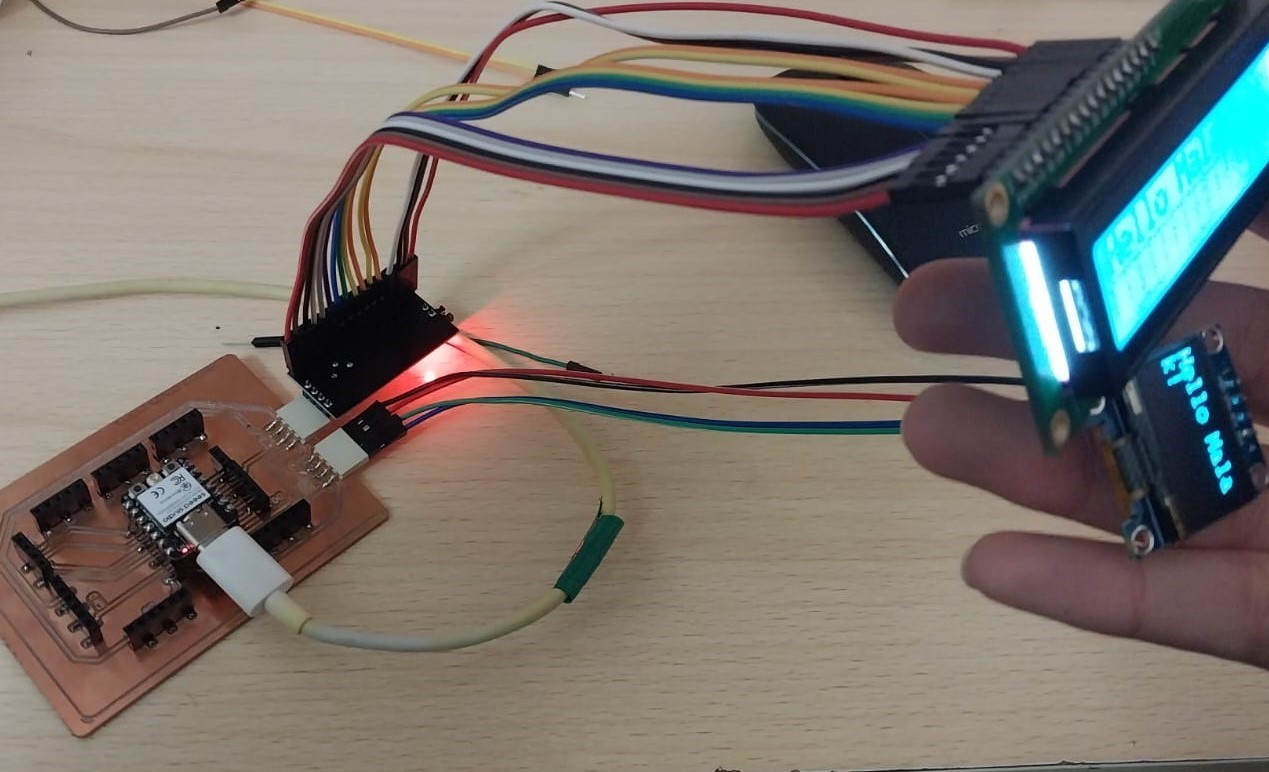
For this test I am using a 16x2 LCD display and the same OLED display that I used in the previous test.
Connection:
To connect the LCD and OLED displays, I used the following connections:
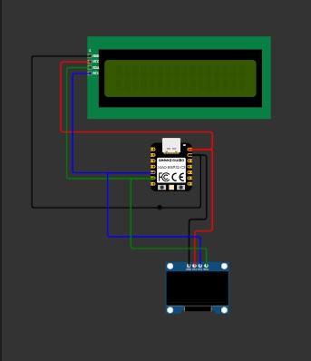
 Note: I had to connect my LCD to an I2C interface module to be able to connect it using the I2C communication protocol. Here is a good guide for connecting an LCD using an I2C interface module: How to Use I2C LCD with ESP32 on Arduino IDE.Note: Since both displays use the I2C communication protocol, I connected the SDA and SCL pins of both displays to the same pins on the microcontroller (SDA to GPIO 6 and SCL to GPIO 7). This allows me to control both displays using the same I2C bus.
Here is the connection diagram using Wokwi.
Code:
                        #include <Wire.h>
#include  <Adafruit_GFX.h>
#include  <Adafruit_SSD1306.h>
#include  <LiquidCrystal_I2C.h>

// OLED settings
#define SCREEN_WIDTH 128
#define SCREEN_HEIGHT 64
Adafruit_SSD1306 oled(SCREEN_WIDTH, SCREEN_HEIGHT, &Wire, -1);

// LCD settings (change 0x27 if needed)
LiquidCrystal_I2C lcd(0x27, 16, 2);

void setup() {
  Wire.begin(6, 7); // SDA, SCL for ESP32-C3

  Serial.begin(115200);

  // OLED start
  if (!oled.begin(SSD1306_SWITCHCAPVCC, 0x3C)) {
    Serial.println("OLED not found");
    while (1);
  }

  oled.clearDisplay();
  oled.setTextSize(2);
  oled.setTextColor(SSD1306_WHITE);

  // LCD start
  lcd.init();
  lcd.backlight();

  // Print on OLED
  oled.setCursor(0, 10);
  oled.println("Hello Malak!");
  oled.display();

  // Print on LCD
  lcd.setCursor(0, 0);
  lcd.print("Hello Malak!");
}

void loop() {
  // nothing for now
}
This code initializes both the OLED and LCD displays, prints "Hello Malak!" on both screens, and then does nothing in the loop. This allows you to compare the display quality and readability of both types of screens.
You can download the code from here.
And here is the testing process:
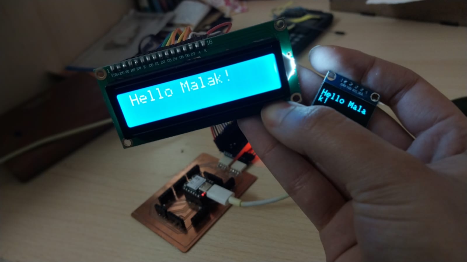
After testing both displays, I found that the OLED display has better contrast and is easier to read from different angles compared to the LCD display. Therefore, I decided to use the OLED display for my final project.
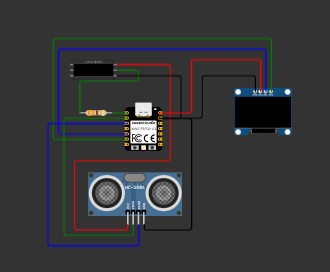
Integrating the Circuit
After deciding to use the OLED display for my final project, I integrated it with the ultrasonic sensor and neopixel LEDs to create a simple distance measurement display. The OLED displays the distance measured by the ultrasonic sensor, and the neopixel LEDs change color based on the distance.
Connection:
To connect the OLED display with the ultrasonic sensor and neopixel LEDs, I used the following connections:
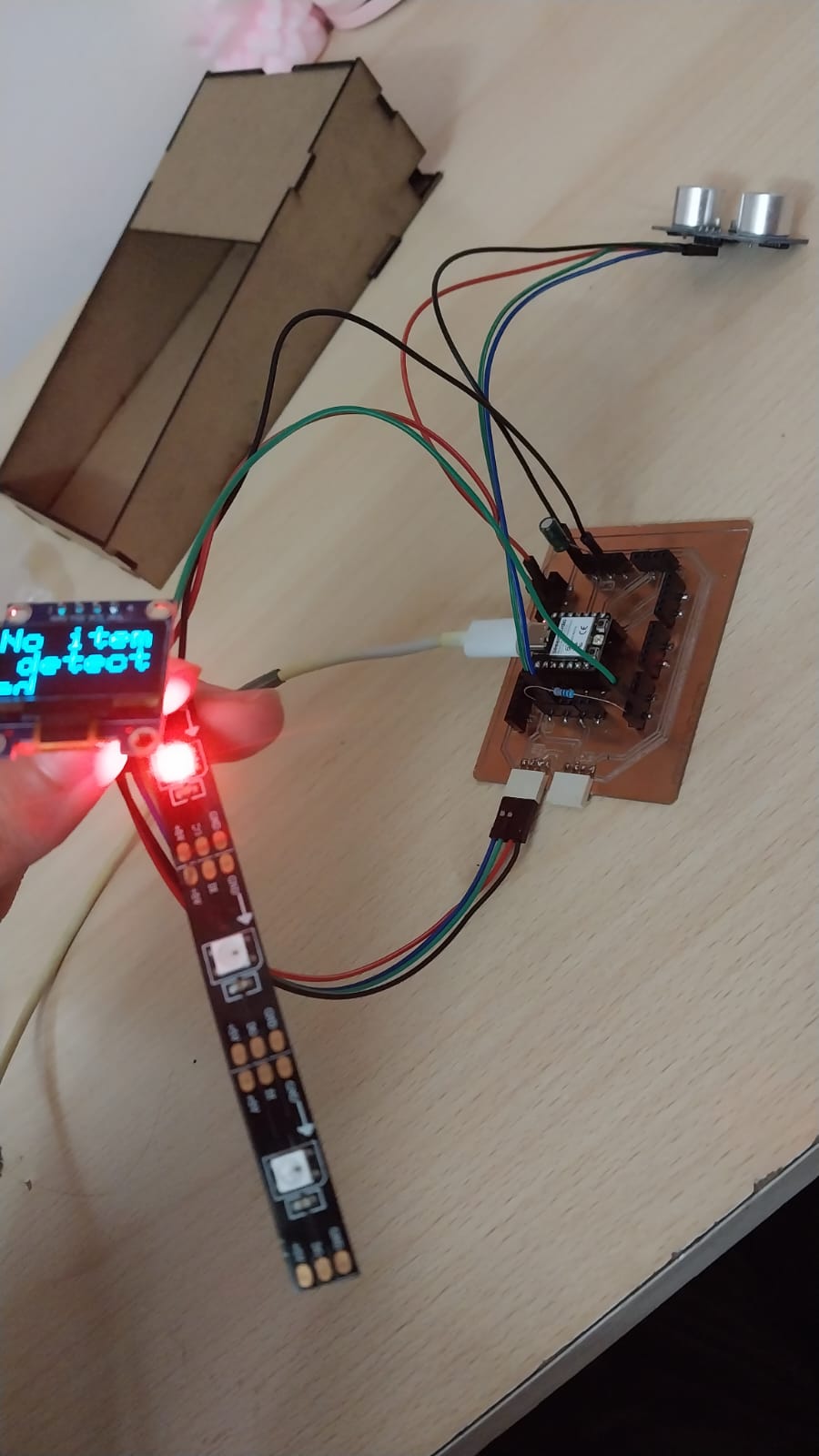
Here is the connection diagram using Wokwi.
Code:
#include  <Wire.h>
#include  <Adafruit_GFX.h>
#include  <Adafruit_SSD1306.h>

#define SCREEN_WIDTH 128
#define SCREEN_HEIGHT 64

Adafruit_SSD1306 display(SCREEN_WIDTH, SCREEN_HEIGHT, &Wire, -1);

#define TRIG_PIN 3
#define ECHO_PIN 4

long duration;
float cm, inches;
#include  <Adafruit_NeoPixel.h>
#ifdef __AVR__
 #include  <avr/power.h> // Required for 16 MHz Adafruit Trinket
#endif

// Which pin on the Arduino is connected to the NeoPixels?
#define PIN        2 // On Trinket or Gemma, suggest changing this to 1

// How many NeoPixels are attached to the Arduino?
#define NUMPIXELS 3 // Popular NeoPixel ring size

// When setting up the NeoPixel library, we tell it how many pixels,
// and which pin to use to send signals. Note that for older NeoPixel
// strips you might need to change the third parameter -- see the
// strandtest example for more information on possible values.
Adafruit_NeoPixel pixels(NUMPIXELS, PIN, NEO_GRB + NEO_KHZ800);

#define DELAYVAL 500 // Time (in milliseconds) to pause between pixels

void setup() {
  Serial.begin(115200); // ESP32 usually uses higher baud

  pinMode(TRIG_PIN, OUTPUT);
  pinMode(ECHO_PIN, INPUT);
#if defined(__AVR_ATtiny85__) && (F_CPU == 16000000)
  clock_prescale_set(clock_div_1);
#endif

    Wire.begin(6, 7);

  display.begin(SSD1306_SWITCHCAPVCC, 0x3C);
  pixels.begin(); // INITIALIZE NeoPixel strip object (REQUIRED)
}

void loop() {
  // Clean trigger
  digitalWrite(TRIG_PIN, LOW);
  delayMicroseconds(5);

  // Send pulse
  digitalWrite(TRIG_PIN, HIGH);
  delayMicroseconds(10);
  digitalWrite(TRIG_PIN, LOW);

  // Read echo
  duration = pulseIn(ECHO_PIN, HIGH);

  // Convert to distance
  cm = (duration / 2.0) / 29.1;
  inches = (duration / 2.0) / 74.0;
pixels.clear();
  display.clearDisplay();
  display.setTextColor(SSD1306_WHITE);

  display.setTextSize(3);
  display.setCursor(0, 0);

  // LED control
  if (cm < 18) {
     pixels.setPixelColor(0, pixels.Color(0,255, 0));
      display.println("Item detected");
  } else {
         pixels.setPixelColor(0, pixels.Color(255,0, 0));
          display.println("No item detected");
  }
    pixels.show();
  display.display();
  // Print
  Serial.print(inches);
  Serial.print(" in, ");
  Serial.print(cm);
  Serial.print(" cm");
  Serial.println();

  delay(50);
}
And here is the testing process: