Week 18: Invention, Intellectual Property, and Income
1. Invention, Intellectual Property, and Income
My final project is a robotic gripper that explores how mechanical design, electronics, and programming can work together to pick up and hold objects. I wanted to take the project beyond a 3D model and understand how the different components actually behave once they are built and assembled.
I started by developing the mechanical design and exploring the gear mechanism, linkages, and component placement. I then moved on to fabrication, using 3D printing, CNC machining, and lathe machining to make the physical components. Alongside this, I worked on the PCB design and the electronics needed to control the mechanism.
Right now, my main focus is getting the servo movement right. The mechanism needs to move smoothly while overcoming the resistance created by the gears. I am testing the MG90S servo with a Seeed Studio XIAO RP2040 on its own before moving on to the complete integration.
Intellectual Property
The intellectual property of this project lies in the mechanical design, the way the components are integrated, and the electronics and code developed for the system. I have not filed for a patent or registered any intellectual property at this stage. My immediate priority is to complete the prototype, test its functionality, and document the process properly.
Licence
I've chosen to share this project under the Creative Commons Attribution-NonCommercial-ShareAlike 4.0 International (CC BY-NC-SA 4.0) licence.
This means anyone can copy, adapt and build on my designs, files and code, as long as they:
- credit me as the original author,
- don't use it commercially, and
- share their version under the same licence.
I chose it because I want other students and makers to learn from and remix the gripper, while keeping the option to develop it commercially myself later. The licence notice also appears in the footer of every page on this site.
Future Possibilities
In the future, the project could be developed further for educational robotics, small-scale object handling, or customised automation. It could also become a learning kit or be shared as an open-source project. These are possibilities I would like to explore once the design and its performance have been validated.
2. Dissemination Plan
I plan to document the complete development process on my Fab Academy website, from the initial design to the final prototype. I want the documentation to show not only what worked, but also the problems I faced and the changes I made along the way.
The documentation will include:
- Concept and design: initial sketches, design explorations, 3D models, and the development of the gripping mechanism.
- Mechanical fabrication: 3D printing, CNC machining, lathe machining, and the process of fitting and assembling the components.
- PCB and electronics: circuit development, PCB layout, PCB milling, component assembly, and wiring.
- Programming: microcontroller setup, servo-control code, and testing the movement of the mechanism.
- Testing and improvements: problems with alignment, resistance, and movement, and the adjustments made to improve the design.
- Final outcome: photographs, a demonstration video, and a summary of what the prototype can do and what still needs improvement.
I will also include the project in my product design portfolio to show my experience with digital fabrication, mechanical prototyping, electronics, and iterative development. The CAD files, PCB files, and code I publish will be shared under the CC BY-NC-SA 4.0 licence above, with credit given to any third-party designs, libraries, or references I used.
3. Final Project Presentation
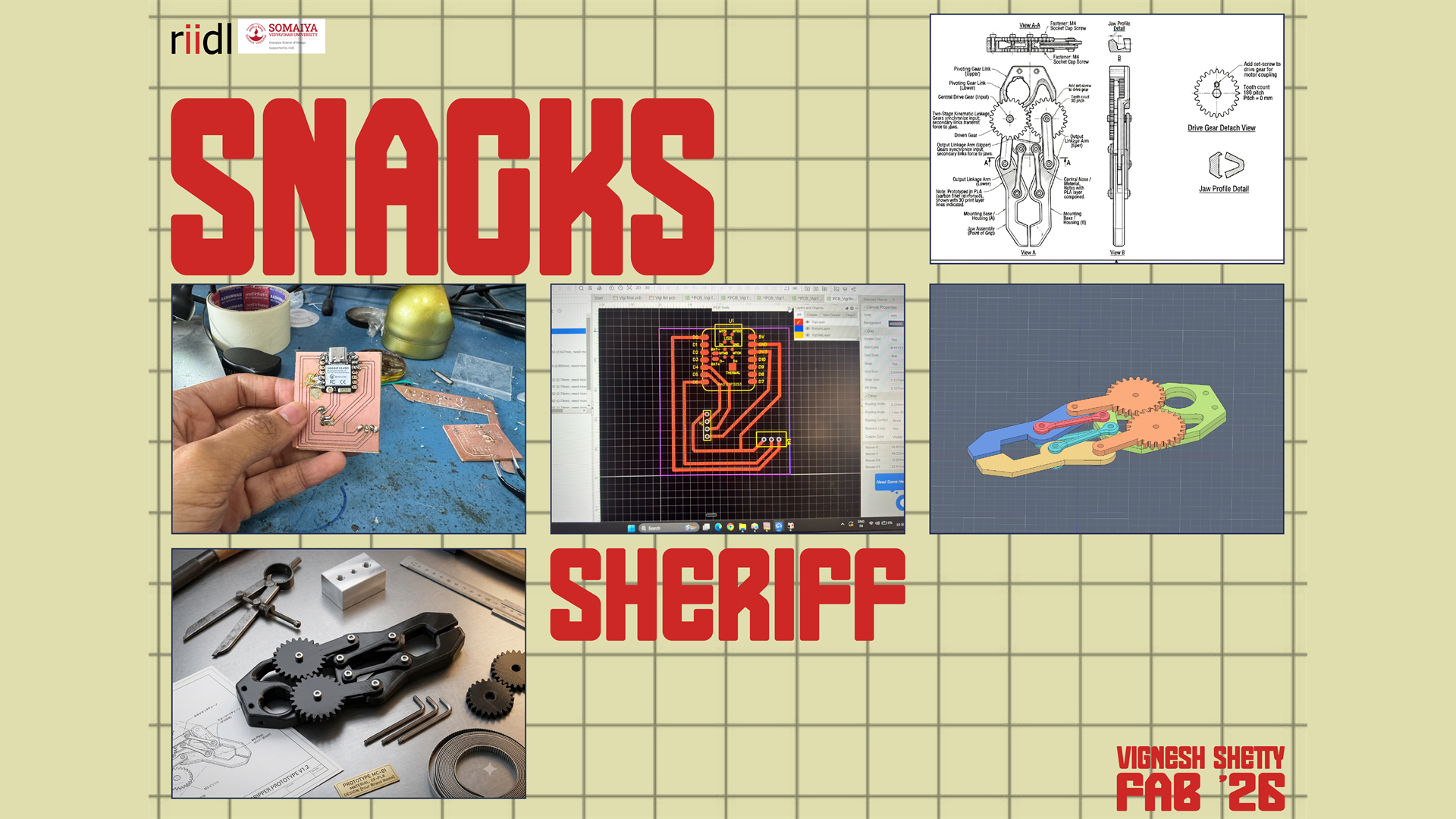
Summary slide
Summary video
Both files are stored at the root of this site as presentation.png (1920×1080) and presentation.mp4 (1920×1080, about 1 minute, under 25 MB), as Fab Academy requires.
4. Progress Tracker
What tasks have been completed, and what tasks remain?
Completed / explored
- Developed the concept and mechanical design of the robotic gripper.
- Created 3D models to understand the geometry and assembly of the mechanism.
- Explored the gear-based gripping mechanism and component placement.
- Worked on physical fabrication using 3D printing and machining.
- Attempted lathe machining for custom mechanical components.
- Worked on the electronics and PCB design.
- Started setting up the microcontroller and servo connections.
- Began testing servo movement through code.
Still to be completed
- Finalise the mechanical components and their fit.
- Resolve the movement and resistance issues in the gear mechanism.
- Get smooth, controlled servo movement under the intended load.
- Complete the electronics and verify the final connections.
- Integrate the electronics with the complete gripper.
- Test the gripper with suitable objects and check whether it holds them reliably.
- Record the final demonstration and complete the Fab Academy documentation.
What's working? What's not?
What's working
The initial mechanical design and 3D models have helped me understand how the gripping mechanism should come together. Making the physical components has shown me where the real fit and movement need more attention. I have also started testing the servo and microcontroller separately, which is helping me understand the control system before I integrate everything.
What's not working / needs improvement
The main challenge is getting smooth movement despite the resistance created by the gear mechanism. Component alignment, fit, and the amount of torque required still need to be checked. I am also working through the electronics setup to make sure the servo gets enough power and responds reliably to the code.
The complete gripper has not been fully validated yet, so I need to test the assembled mechanism before deciding whether further mechanical or electronic changes are needed.
What questions need to be resolved?
- Is the selected servo powerful enough to move the gear mechanism under load?
- How can I reduce friction and resistance to get smoother movement?
- Are the gears and linkages aligned correctly?
- Is the power supply sufficient for reliable servo operation?
- How should the electronics be arranged for a cleaner and more reliable integration?
- Can the gripper repeatedly pick up and hold objects without slipping?
- Which project files and instructions should be shared publicly?
What will happen when?
| Stage | Planned work |
|---|---|
| Current stage | Test the servo, check the wiring, and adjust the movement code. |
| Next stage | Refine the mechanical components and complete the gripper assembly. |
| Integration | Connect the electronics to the mechanism and test the complete system. |
| Final testing | Check gripping performance, movement consistency, and reliability. |
| Documentation | Record the final demonstration and publish the project documentation, design files, and relevant code. |
The timeline depends on how quickly the current movement and assembly issues are resolved. I will prioritise getting the mechanism working reliably before moving on to the final documentation.
What have I learned?
This project has taught me that getting a mechanism to work physically is very different from designing it digitally. Even when the 3D model looks right, alignment, friction, material, and fabrication tolerances can change how the mechanism performs.
I have also learned the value of testing each part separately before combining everything. Testing the servo and controller on their own is helping me pinpoint problems instead of trying to troubleshoot the whole system at once.
Working across mechanical fabrication, PCB design, electronics, and programming has shown me how closely these parts depend on each other. My next focus is to resolve the movement issues, complete the integration, and test the gripper with real objects so I can judge its performance on actual results.