Week 16: Wildcard Week
Assignment: design and produce something with a digital fabrication process (incorporating computer-aided design and manufacturing) not covered in another assignment, documenting the requirements that your assignment meets, and including everything necessary to reproduce it.
Custom coupler fabrication using the lathe machine
As part of Wildcard Week, I used the centre lathe machine to manufacture a custom mechanical coupler. I designed it around the MG90S servo motor, the same servo used in my gripper, as a coupler between the servo and a rotating shaft. It was a machining exercise and is not used in the final gripper.
The part was machined from a cylindrical stock by first turning it to the required outer diameter and then creating a precise central hollow bore. Each side of the coupler was designed with a different purpose:
- One side was machined with a recessed hole to accommodate a fastening screw. This allows the coupler to be securely mounted to the rotating shaft, preventing any unwanted movement during operation.
- The opposite side was machined to match the spline profile of the MG90S servo horn. This pocket allows the servo's output gear to fit tightly into the coupler, creating a positive mechanical lock that efficiently transfers the servo's rotational motion to the gripper mechanism.
Machining this component on the lathe provided significantly better dimensional accuracy and concentricity than would have been possible through 3D printing. Since the part transmits torque directly from the servo motor, maintaining precise tolerances was essential to eliminate backlash, improve alignment, and ensure reliable power transmission.
This exercise also strengthened my understanding of lathe operations, including facing, centre drilling, boring, internal diameter machining, and achieving accurate fits for mating mechanical components. Although the coupler is not part of the final project, making it showed me how a machined part can give a more precise and stronger servo connection than a printed one.
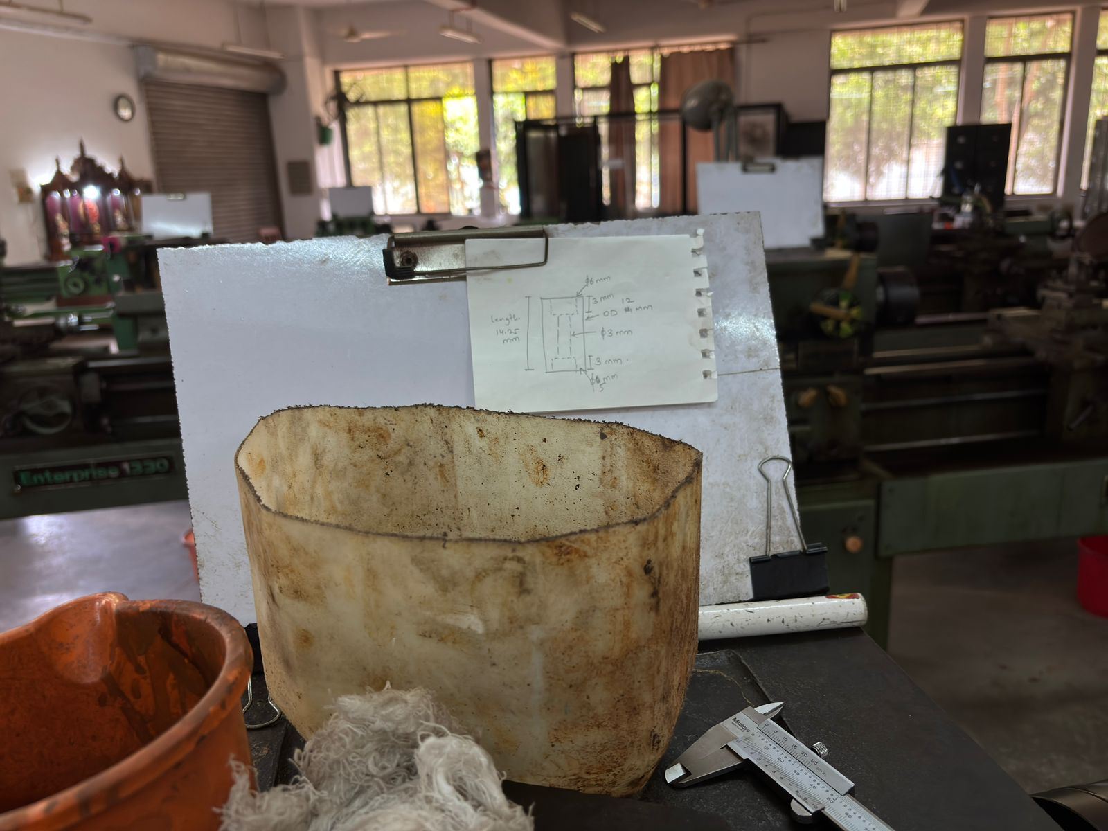
Before machining, I sketched the coupler with its key dimensions (overall length 14.25 mm, outer diameter 12 mm, and the bore sizes for each end) and kept the sketch next to the machine as a reference.
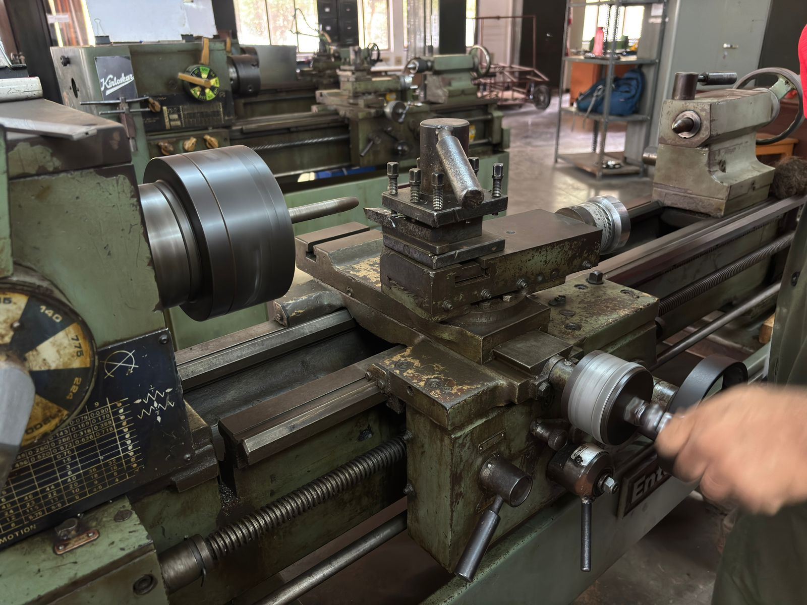
The coupler was turned on a conventional centre lathe in the workshop.
Turning on the lathe: the stock spins in the chuck while the cutting tool on the tool post removes material.
Grinding on the bench grinder.
Machining parameters
| Parameter | Value |
|---|---|
| Stock | Cylindrical metal rod (exact material grade and starting diameter not recorded) |
| Target dimensions | 12 mm outer diameter, 14.25 mm overall length, with the bore sizes from the hand sketch |
| Spindle speed | Set to suit the material and operation; exact rpm not recorded |
| Tools | HSS turning tool for the outer diameter and facing; drill bits for the central bore |
| Depth of cut | Several light passes down to the final diameter; exact depth per pass not recorded |
I didn't note down the exact rpm, depth of cut or stock size during machining. Next time I would record them so the part can be reproduced exactly.
Final outcome
The finished metal coupler, turned to show its outer diameter and the central bore.
Side experiment: modelling a threaded coupler in Zoo Design Studio
Separately from the lathe part, I tried modelling a coupler-style bush in Zoo Design Studio, a code-based CAD tool where the model is written as a KCL script (main.kcl). This was an experiment to try the tool; it is not the part I machined above and is not used in the final project.
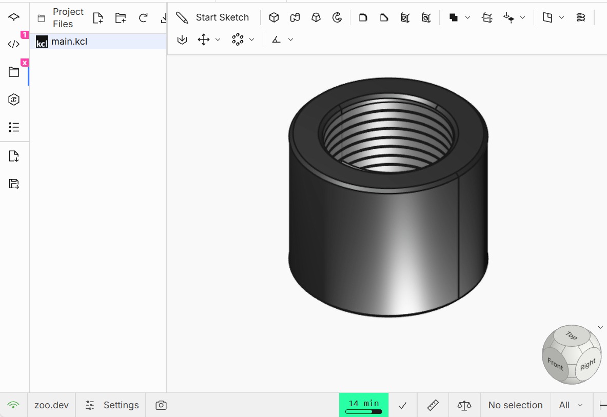
The first version has an internal thread through the bore.
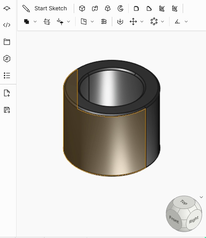
The second view shows a plain-bore version with its outer face selected.
The code that generates the model
Updated after feedback
The lathe part above was turned on a manual lathe, so on its own it has no digital fabrication component. I've now uploaded the KCL code that generates the threaded coupler in Zoo Design Studio, so the model can be regenerated and changed from code.
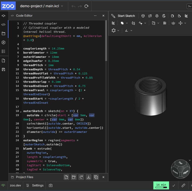
AI note
The KCL code was generated with Zookeeper, Zoo Design Studio's built-in AI assistant, from my prompts and the coupler dimensions (14.25 mm long, 18 mm outer diameter, 12 mm bore, internal thread). I reviewed the parameters, checked the generated model in Zoo, and exported the STEP file from it.
In Zoo the whole part is written as code. Nothing is drawn by hand, and changing a number at the top rebuilds the model. The script builds it in five steps:
- Parameters (lines 5–16): every dimension is a named variable, such as length, bore, outer diameter, chamfer and the thread values.
- Outer body (lines 18–33): an 18 mm circle on the XY plane, extruded 14.25 mm symmetrically and given a metal appearance.
- Bore (lines 35–44): a 12 mm circle extruded slightly longer than the part (+2 mm) and subtracted, which leaves a sleeve.
- Chamfers (lines 46–63): a 0.35 mm chamfer on the four circular edges, inside and outside, top and bottom.
- Internal thread (lines 65–103): a small thread profile is sketched on the XZ plane, swept along a helix of the bore's radius with 1 mm pitch, and subtracted from the coupler. This cuts the helical thread into the bore wall.
| Parameter | Value | What it controls |
|---|---|---|
couplerLength |
14.25 mm | overall length (same as the hand sketch) |
outerDiameter |
18 mm | outside of the coupler |
boreDiameter |
12 mm | hole through the middle |
edgeChamfer |
0.35 mm | chamfer on all four edges |
threadPitch |
1 mm | distance between threads |
threadDepth |
pitch × 0.54 = 0.54 mm | how deep the thread cuts into the wall |
threadEndInset |
pitch × 0.75 = 0.75 mm | thread stops short of each end |
Full KCL code (coupler-threaded.kcl)
// Threaded coupler
// Cylindrical coupler with a modeled internal helical thread.
@settings(defaultLengthUnit = mm, kclVersion = 3.0)

couplerLength = 14.25mm
boreDiameter = 12mm
outerDiameter = 18mm
edgeChamfer = 0.35mm
threadPitch = 1mm
threadDepth = threadPitch * 0.54
threadRootFlat = threadPitch * 0.125
threadProfileWidth = threadPitch * 0.85
threadOverlap = 0.1mm
threadEndInset = threadPitch * 0.75
threadTravel = couplerLength - (2 * threadEndInset)
threadStart = -couplerLength / 2 + threadEndInset

outerSketch = sketch(on = XY) {
  outside = circle(start = [var 9mm, var 0mm], center = [var 0mm, var 0mm])
  coincident([outside.center, ORIGIN])
  horizontal([outside.start, outside.center])
  diameter(outside) == outerDiameter
}
outerRegion = region(segments = [outerSketch.outside])
blank = extrude(
  outerRegion,
  length = couplerLength,
  symmetric = true,
  tagStart = $sleeveBottom,
  tagEnd = $sleeveTop,
)
  |> appearance(color = "#aeb3b4", metalness = 80, roughness = 34)
hide(outerSketch)

boreSketch = sketch(on = XY) {
  bore = circle(start = [var 6mm, var 0mm], center = [var 0mm, var 0mm])
  coincident([bore.center, ORIGIN])
  horizontal([bore.start, bore.center])
  diameter(bore) == boreDiameter
}
boreRegion = region(segments = [boreSketch.bore])
boreTool = extrude(boreRegion, length = couplerLength + 2mm, symmetric = true)
boredSleeve = subtract([blank], tools = [boreTool])
hide(boreSketch)

coupler = chamfer(
  boredSleeve,
  length = edgeChamfer,
  edges = [
    {
      sideFaces = [outerRegion.tags.outside, sleeveTop]
    },
    {
      sideFaces = [outerRegion.tags.outside, sleeveBottom]
    },
    {
      sideFaces = [boreRegion.tags.bore, sleeveTop]
    },
    {
      sideFaces = [boreRegion.tags.bore, sleeveBottom]
    }
  ],
)

threadProfile = sketch(on = XZ) {
  lowerFlank = line(start = [var 5.9mm, var -0.425mm], end = [var 6.54mm, var -0.0625mm])
  root = line(start = [var 6.54mm, var -0.0625mm], end = [var 6.54mm, var 0.0625mm])
  upperFlank = line(start = [var 6.54mm, var 0.0625mm], end = [var 5.9mm, var 0.425mm])
  innerEdge = line(start = [var 5.9mm, var 0.425mm], end = [var 5.9mm, var -0.425mm])
  coincident([lowerFlank.end, root.start])
  coincident([root.end, upperFlank.start])
  coincident([upperFlank.end, innerEdge.start])
  coincident([innerEdge.end, lowerFlank.start])
  vertical(root)
  vertical(innerEdge)
  horizontalDistance([ORIGIN, lowerFlank.start]) == boreDiameter / 2 - threadOverlap
  verticalDistance([ORIGIN, lowerFlank.start]) == -threadProfileWidth / 2
  horizontalDistance([lowerFlank.start, lowerFlank.end]) == threadDepth + threadOverlap
  verticalDistance([lowerFlank.start, lowerFlank.end]) == (threadProfileWidth - threadRootFlat) / 2
  verticalDistance([root.start, root.end]) == threadRootFlat
  verticalDistance([innerEdge.end, innerEdge.start]) == threadProfileWidth
}
threadRegion = region(
  segments = [
    threadProfile.lowerFlank,
    threadProfile.root
  ],
  intersectionIndex = -1,
  direction = CCW,
)
threadHelix = helix(
  axis = Z,
  radius = boreDiameter / 2,
  length = threadTravel,
  revolutions = threadTravel / threadPitch,
  angleStart = 0deg,
  ccw = true,
)
threadTool = sweep(threadRegion, path = threadHelix)
  |> translate(xyz = [0mm, 0mm, threadStart], global = true)
hide(threadProfile)
hide(threadHelix)
threadedCoupler = subtract([coupler], tools = [threadTool])
Design files:
- coupler-threaded.kcl: the KCL code that generates the threaded coupler (open it in Zoo Design Studio).
- coupler-zoo.step: the threaded version exported from Zoo as STEP. It is 18 mm in outer diameter and 14.25 mm long (the same length as the hand sketch); the exact bore and thread are set in the .kcl code above.
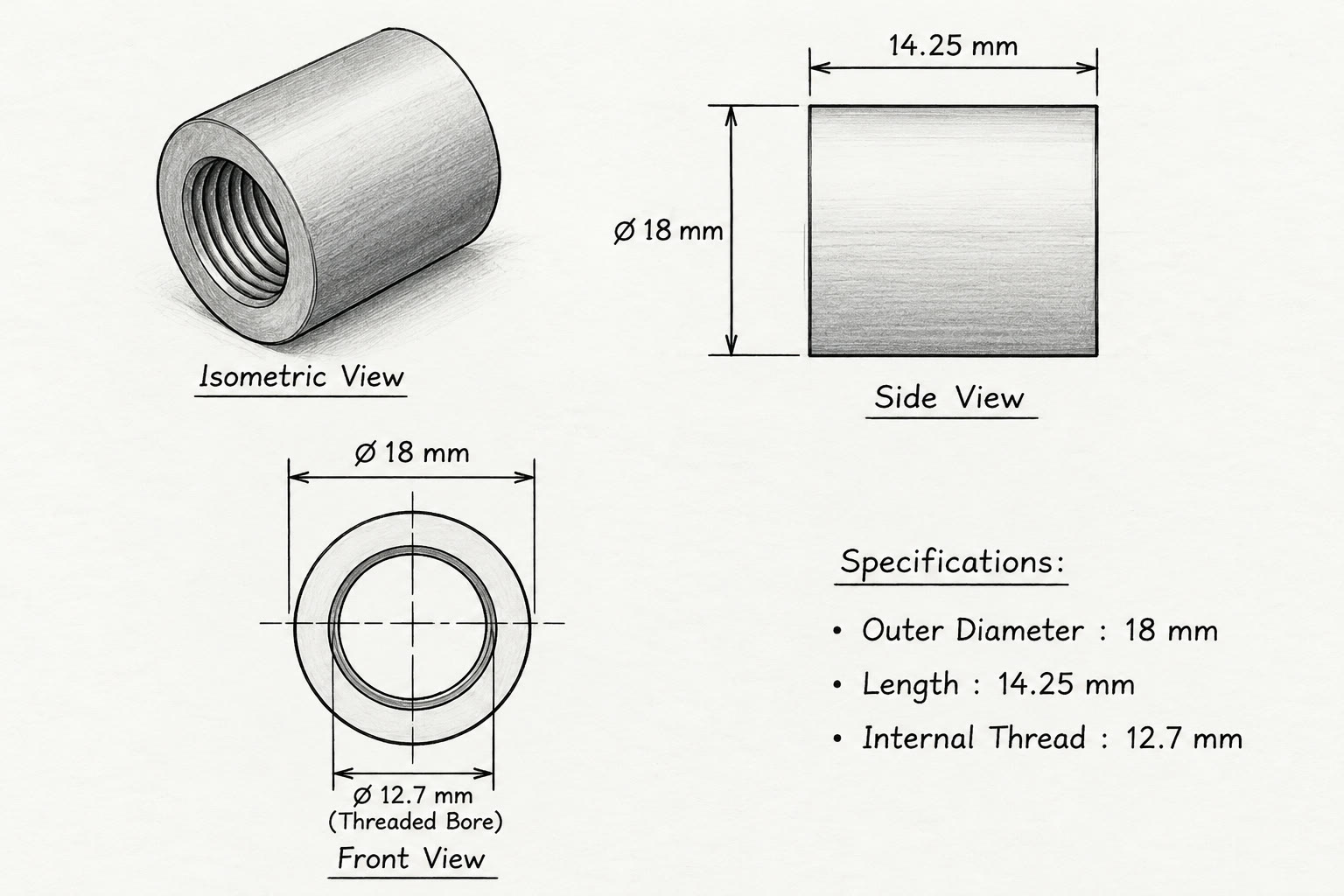
AI-generated illustration (not my own drawing) of the Zoo model's outer dimensions: 18 mm outer diameter and 14.25 mm length. Its "12.7 mm threaded bore" label is not accurate: the code sets a 12 mm bore with a 1 mm-pitch thread cut about 0.54 mm deep (roughly 13.1 mm across the thread roots).