Wildcard Week
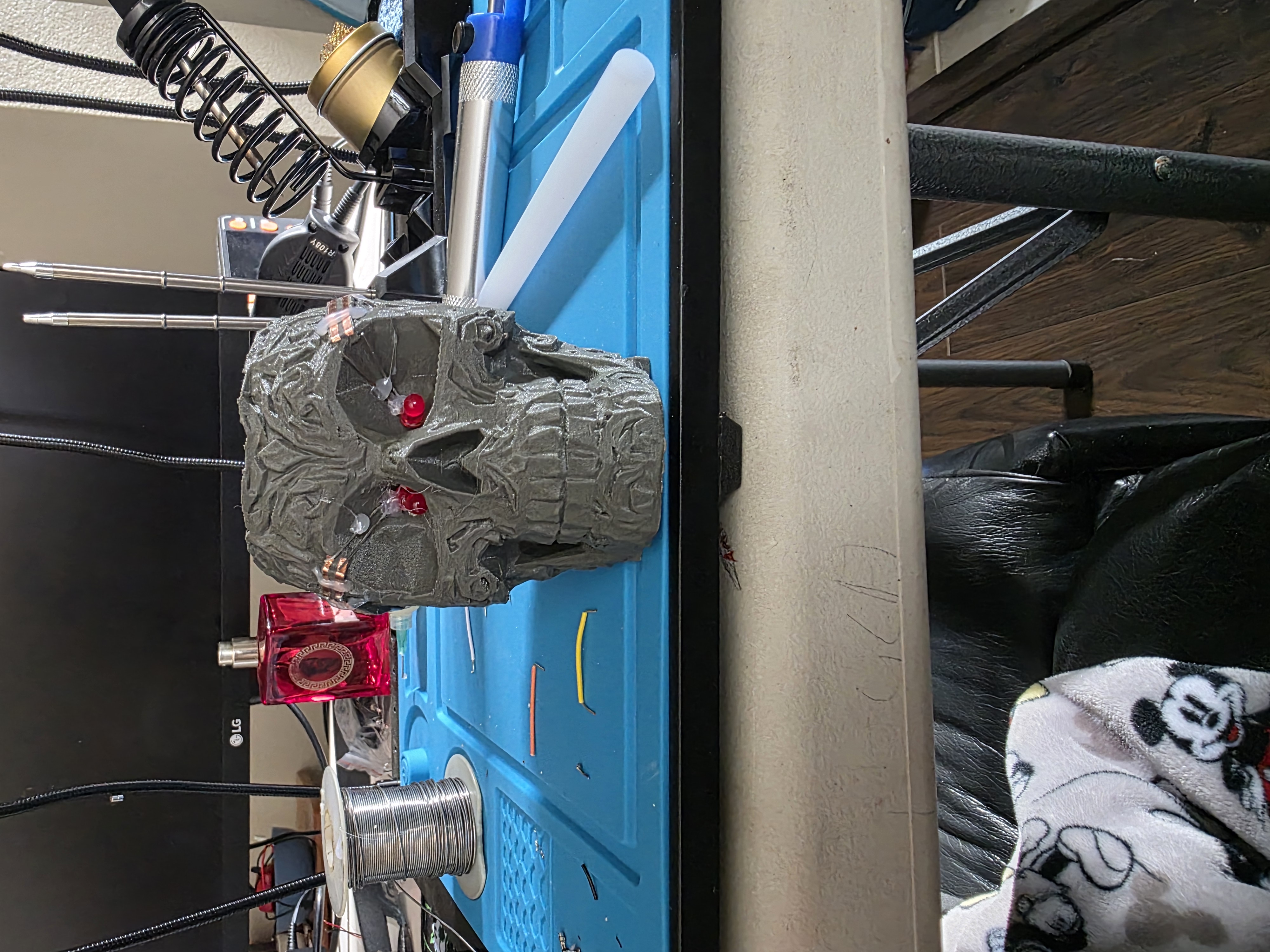
3D printed skull with raised copper traces and blinking LED eyes.
Project Idea
For my Wildcard Week project, I wanted to try something different that I had never done before. I had seen people experimenting with raised traces and custom electronics on 3D printed objects, so I wanted to attempt something similar myself.
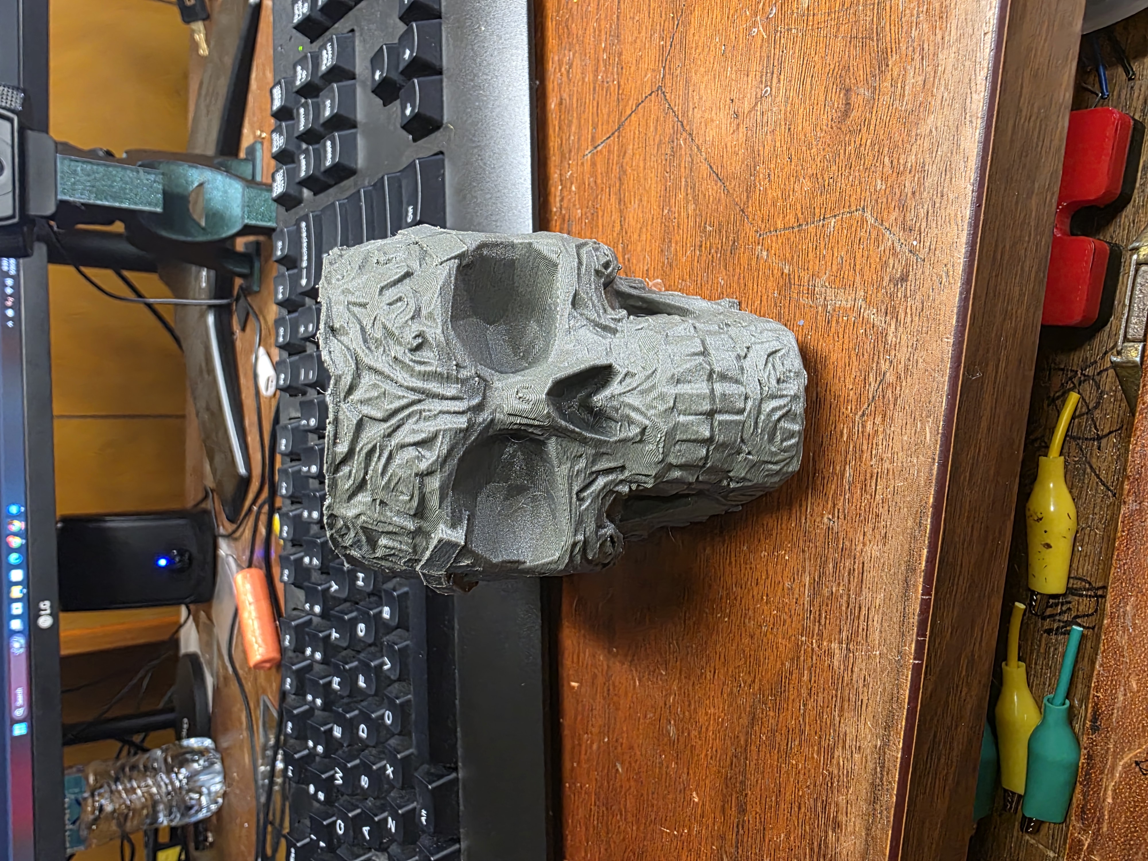
My idea was to create a 3D printed skull with LEDs inside the eyes, nose, and cheek holes. The twist was that I did not want to hide wires inside the skull. Instead, I wanted to create raised traces on the outside of the skull almost like a 3D printed PCB wrapped around the model.
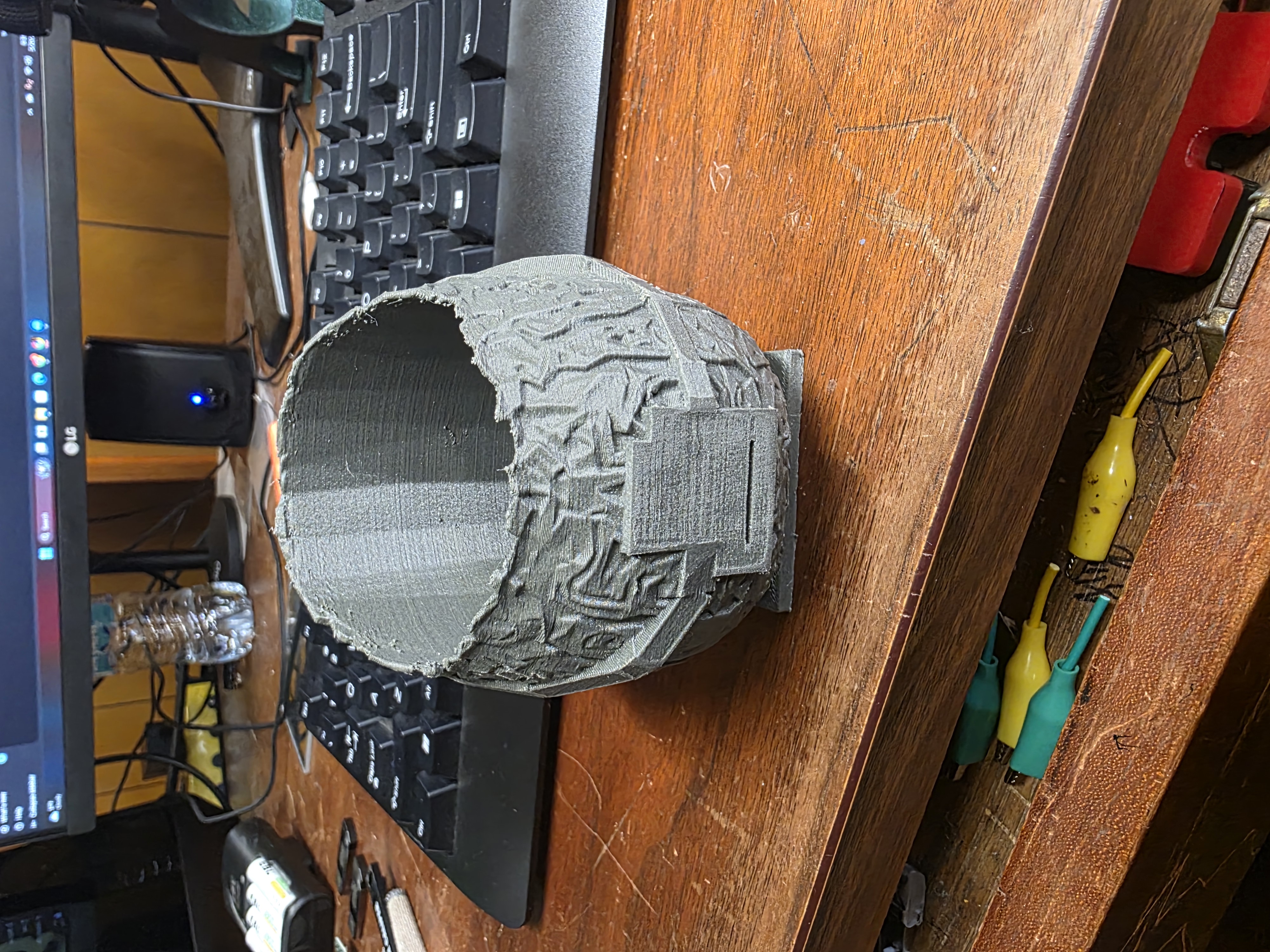
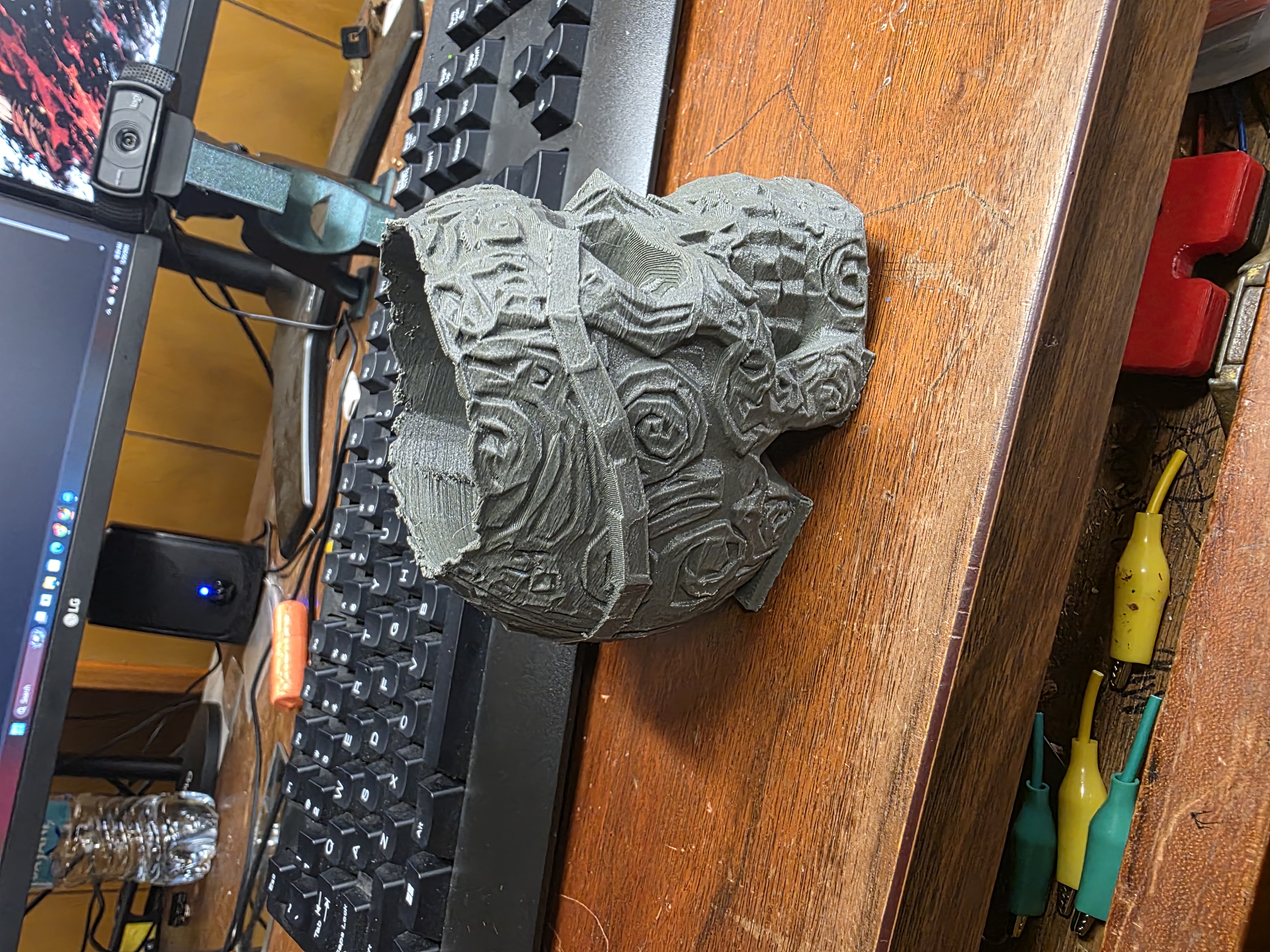
The skull model I started with was originally called Skull Shaper Plot-Planter cover.3mf. It was meant to be a small planter cover, but I really liked the shape and style of the skull, so I used it as the base for this project.
Using the RP2350
For the electronics, I used a Seeed RP2350 board that I had from another project. I wanted the RP2350 to control blinking LEDs and eventually be expandable into more effects later.
I used the Arduino IDE to upload the code and test the LEDs. The first goal was simply getting the left and right eye LEDs blinking at different times.
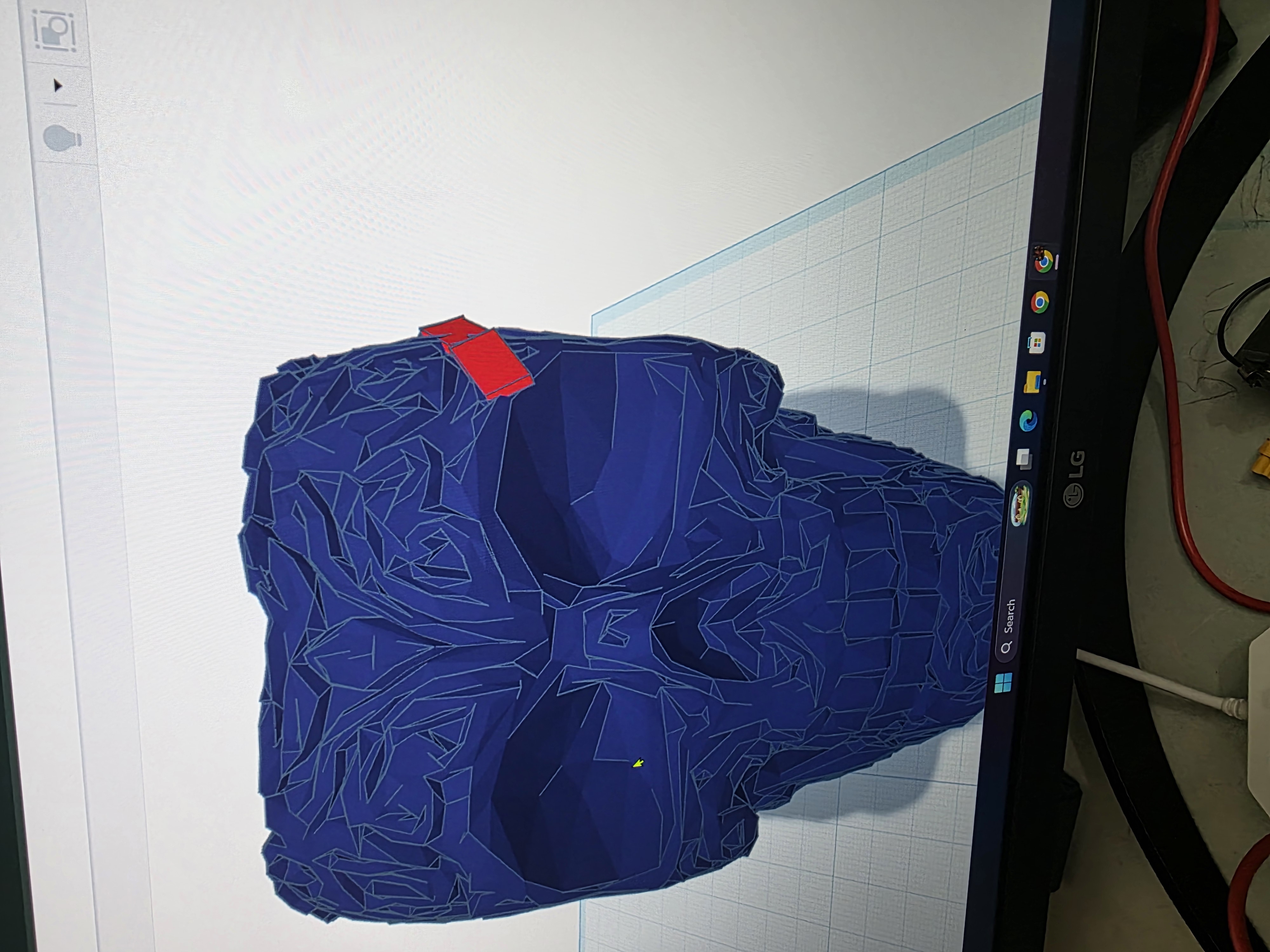
Tinkercad Problems and Blender Cleanup
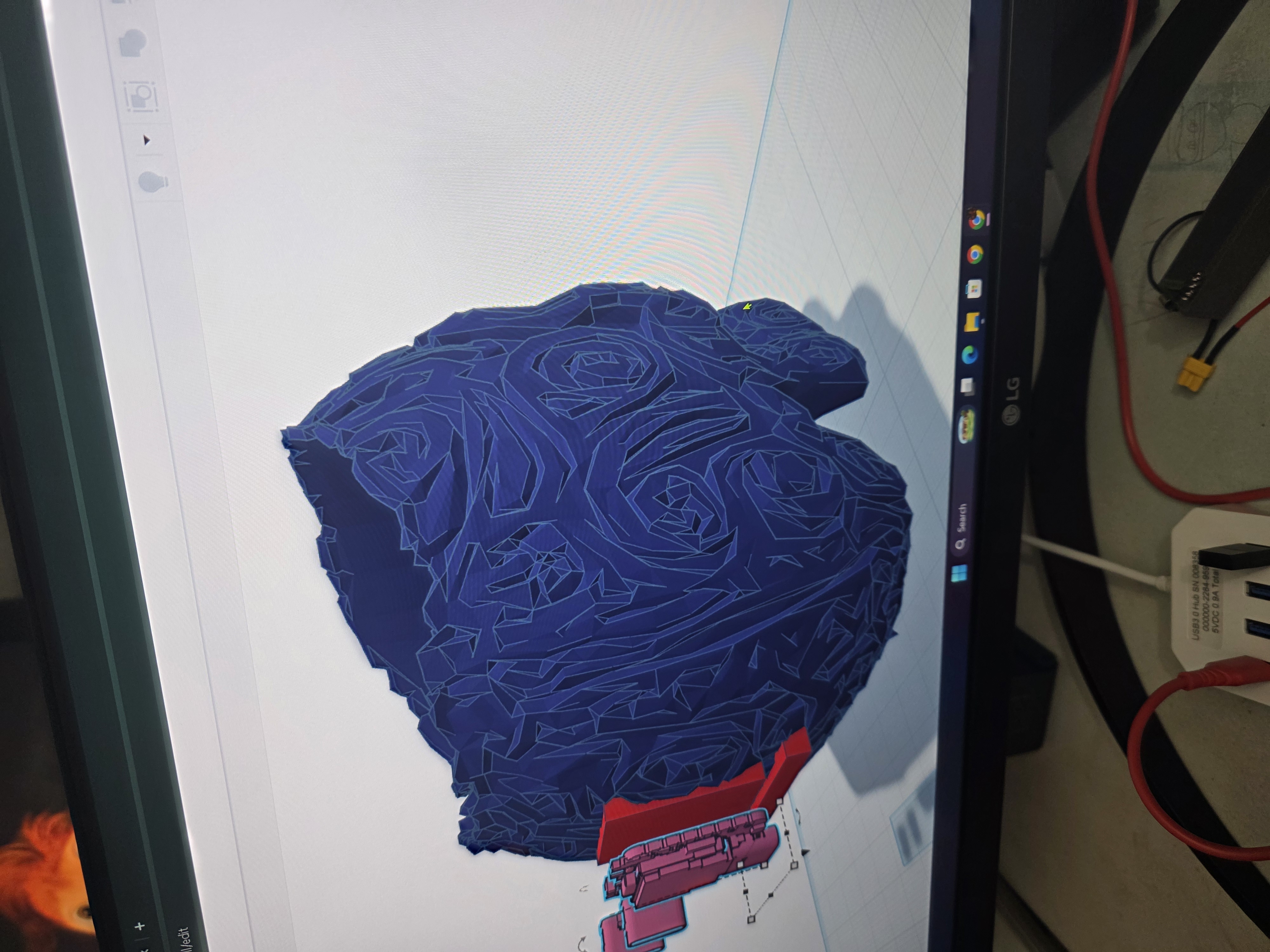
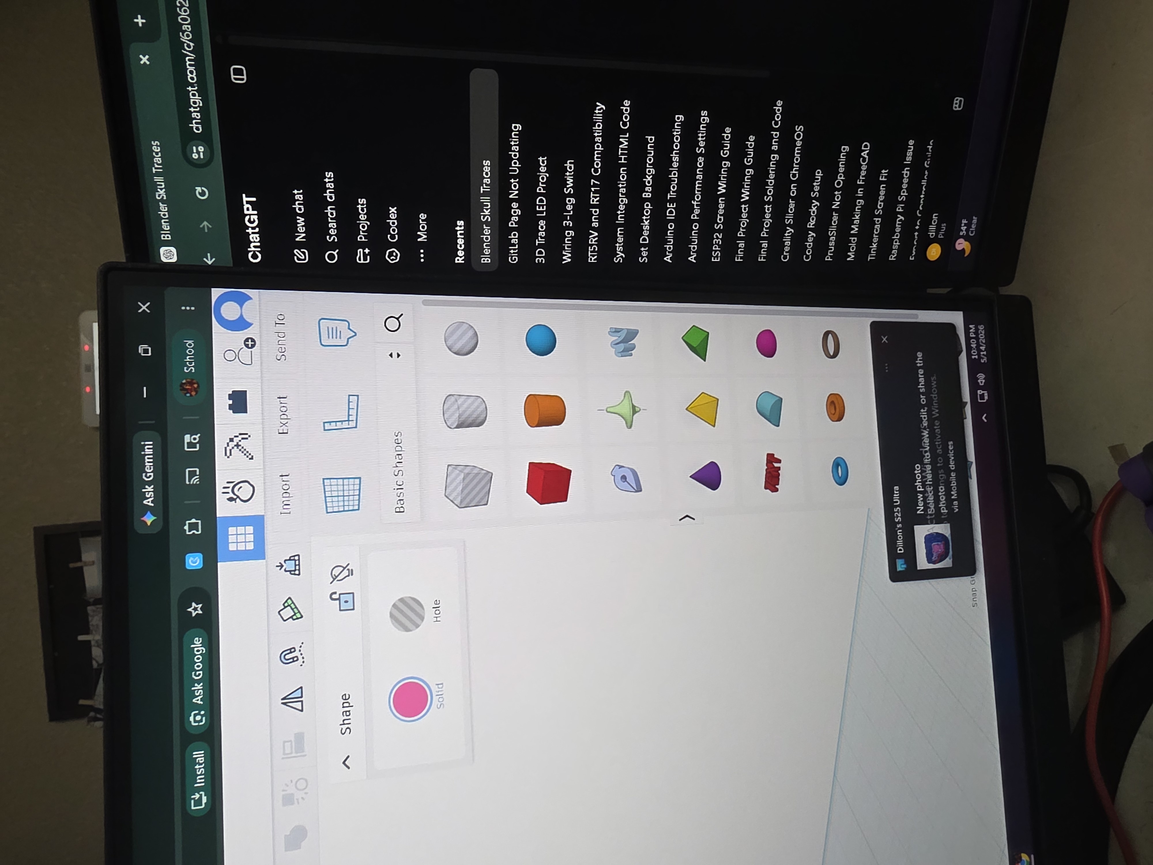
I downloaded a STEP file for the RP2350 board and imported it into Tinkercad along with the skull model. That is when I discovered that Tinkercad absolutely hated the skull model because it had too many tiny triangles and details.
I ended up asking Astra, my ChatGPT assistant, how to fix the issue. The solution was to import the skull into Blender and simplify/remesh the model so Tinkercad could handle it better.
Once the skull was cleaned up in Blender, I imported it back into Tinkercad and finally started building the raised traces around the skull.
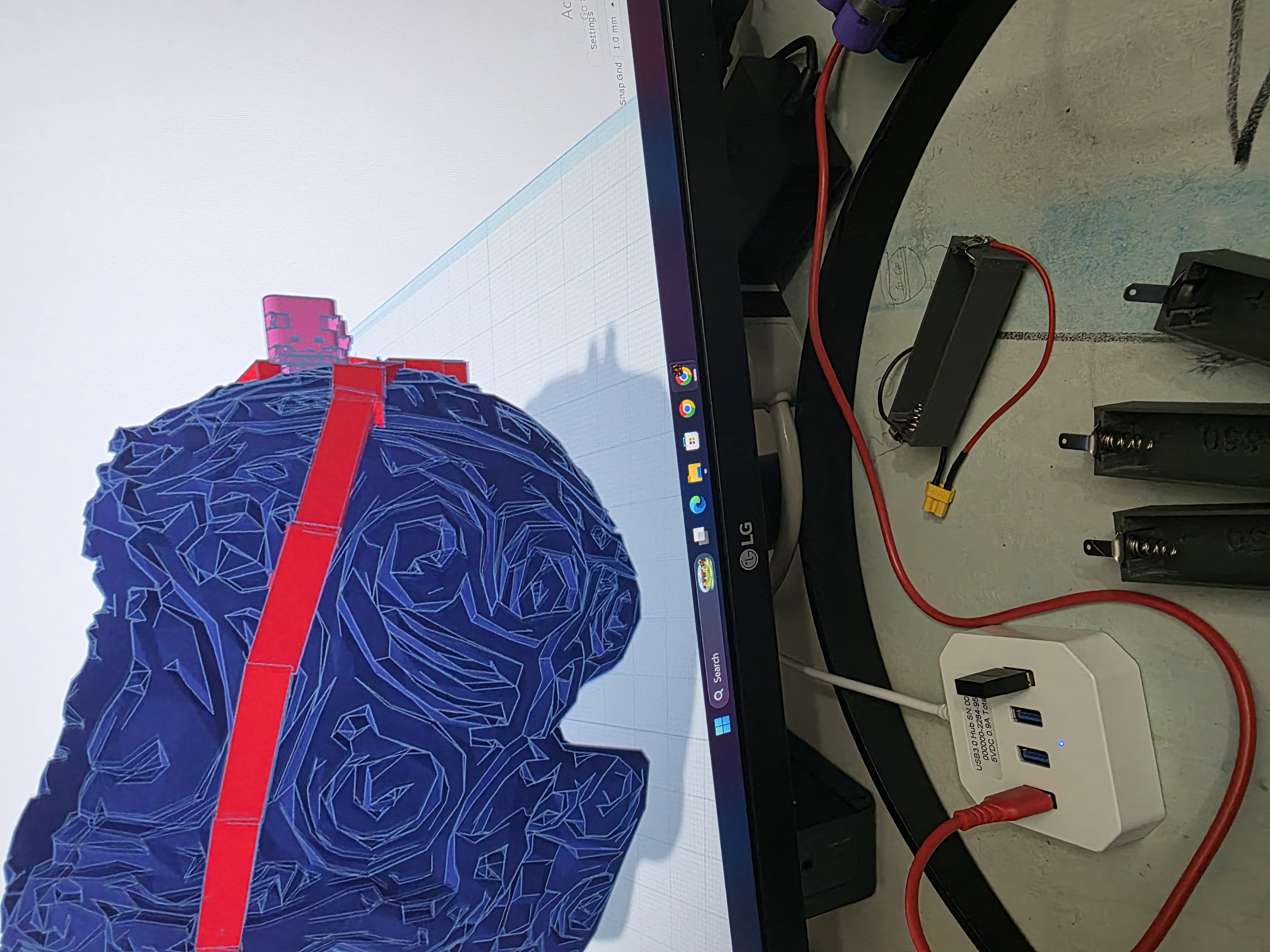

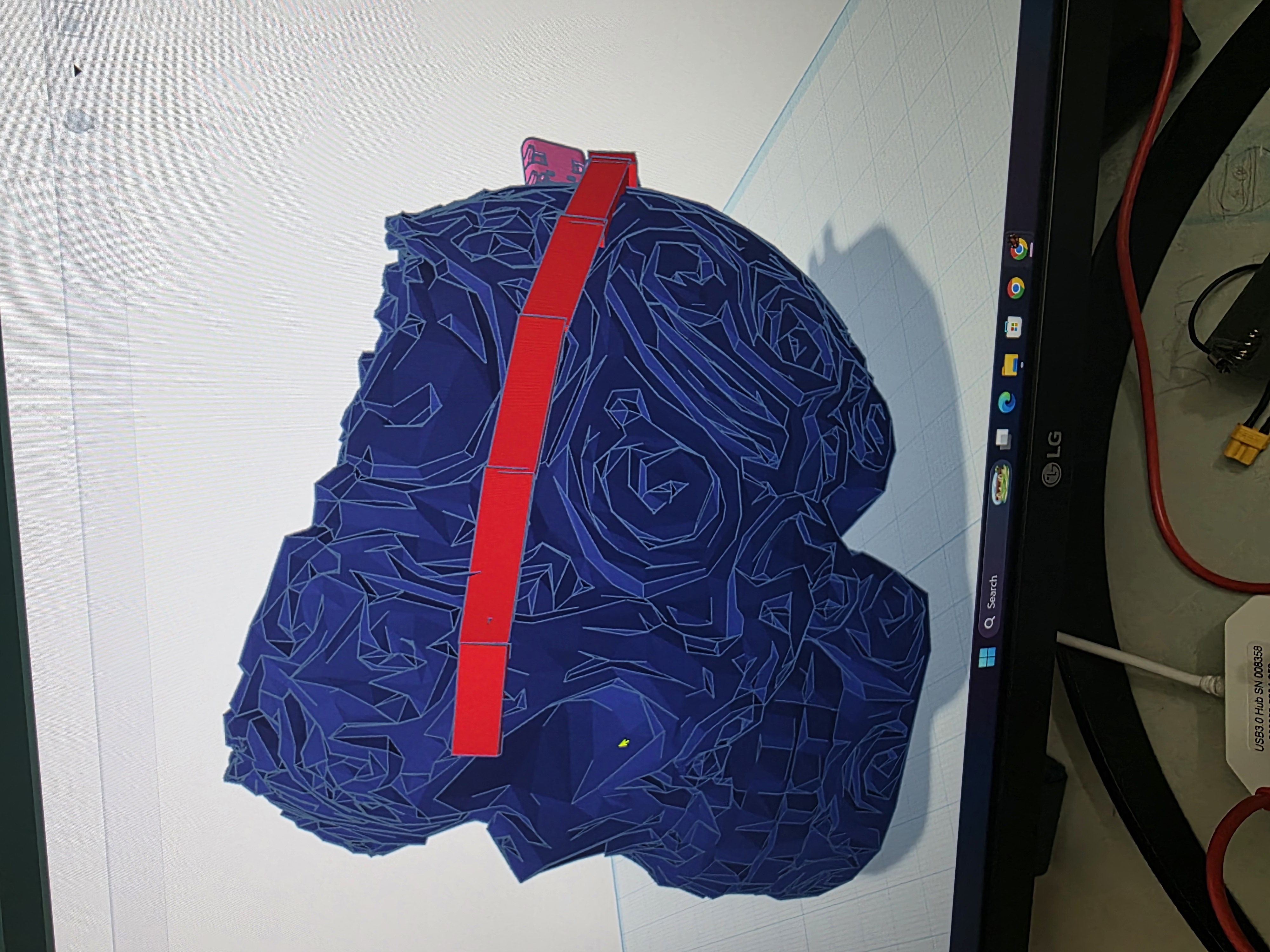

Making the Raised Traces
I originally thought about trying to make the traces directly in Blender, but Blender was much more complicated than I wanted to deal with for this assignment.
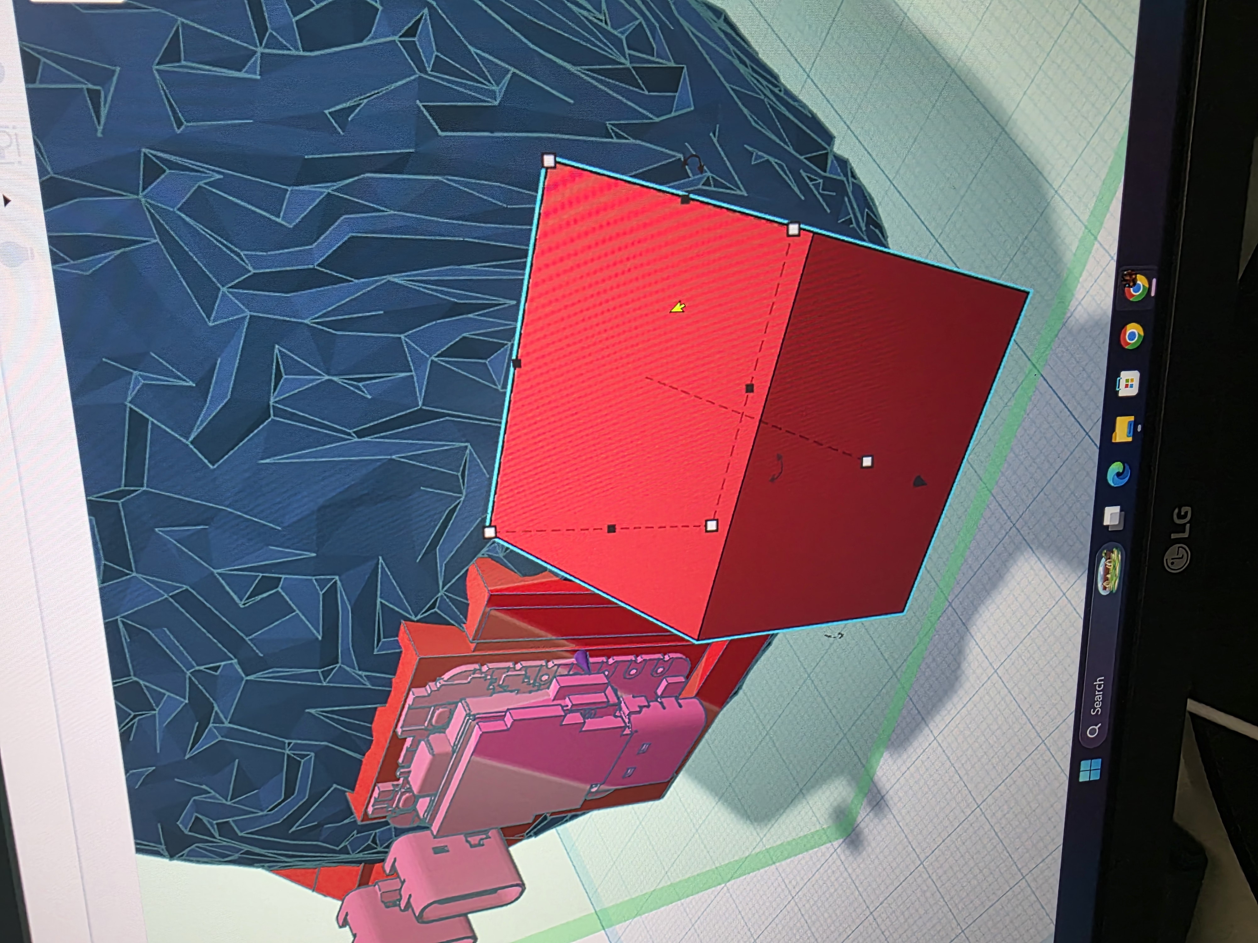
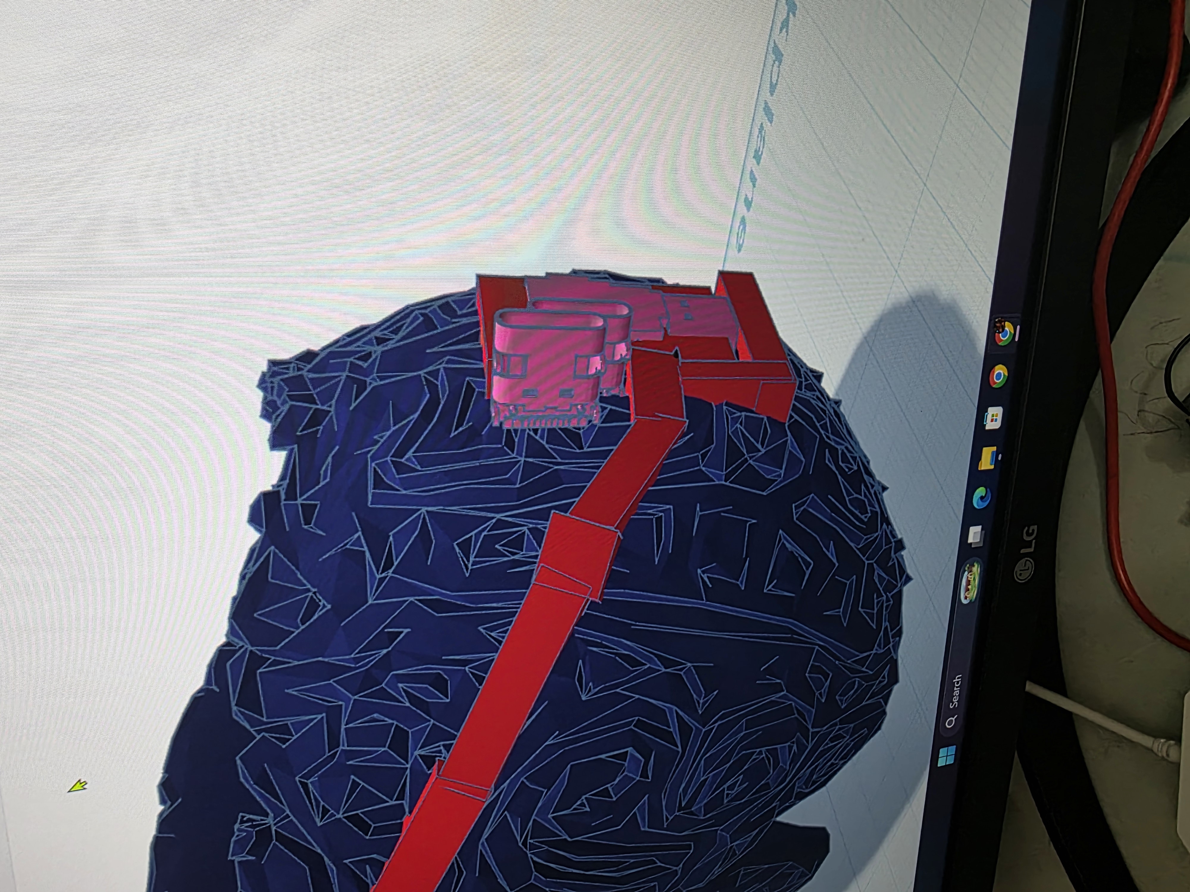
Instead, I made the raised traces block by block directly in Tinkercad. I manually moved and shaped each piece around the skull from the back to the front. It was definitely a slow process and looked a little rough, but honestly the rough style matched the skull pretty well.
The raised traces were designed so copper tape could later sit directly on top of them.
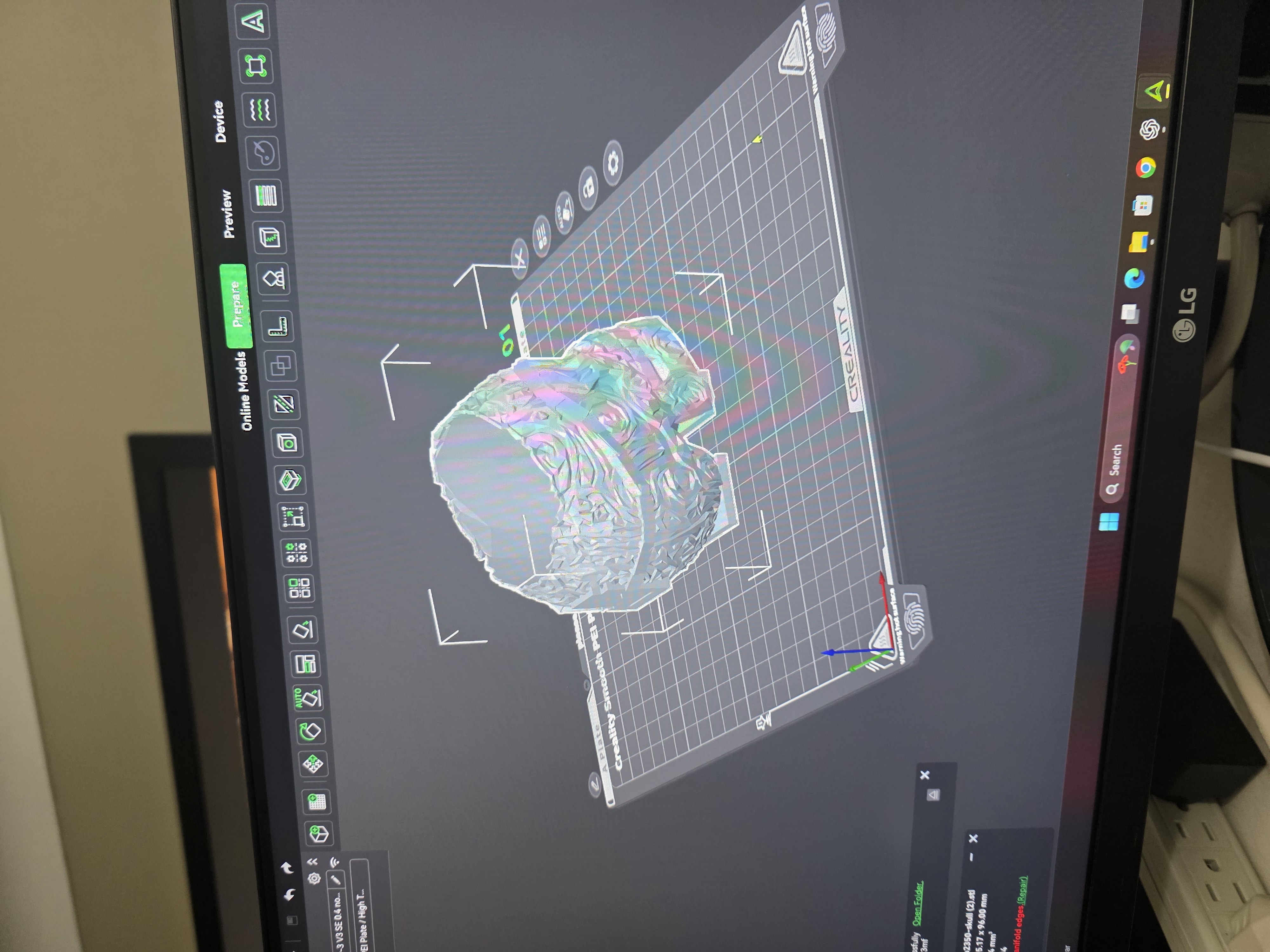
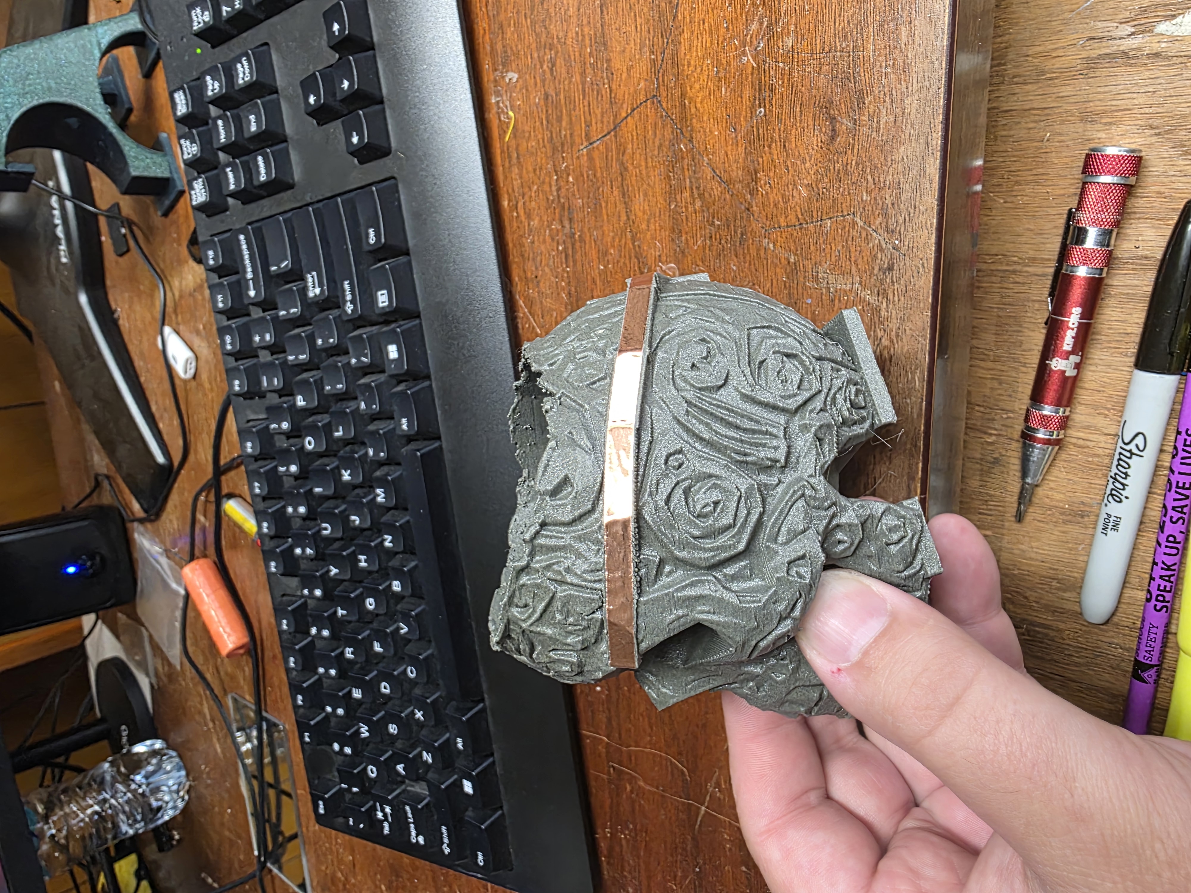
3D Printing the Skull
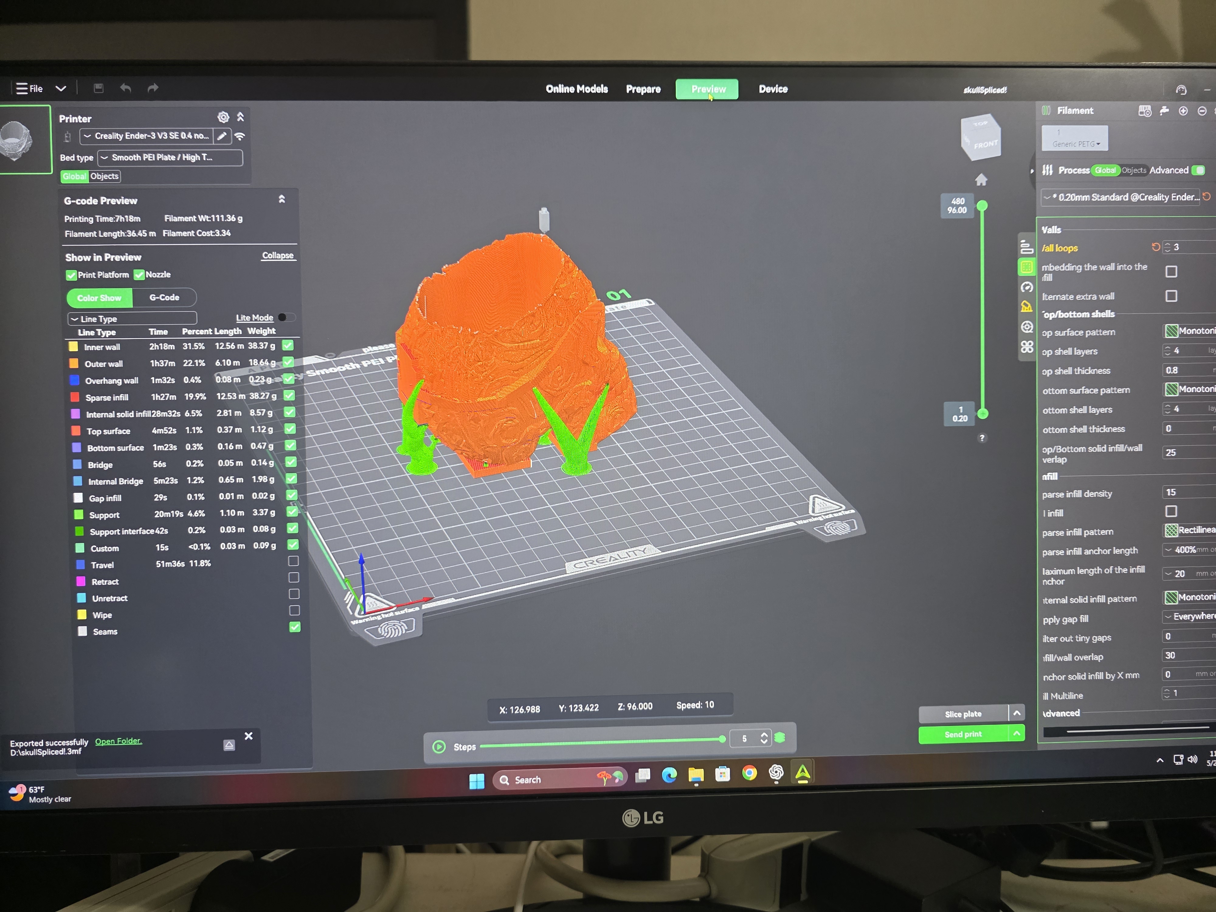
Once the design was finished, I exported it into Creality Slicer and prepared it for printing. I used gray PETG-CF filament because I liked the strong feel and darker appearance of the material.
I quickly discovered that the skull did not want to stick correctly to the printer bed because of the shape. To solve that, I added two flat support plates under the jaw and back of the skull. After adding those plates, the print completed successfully.
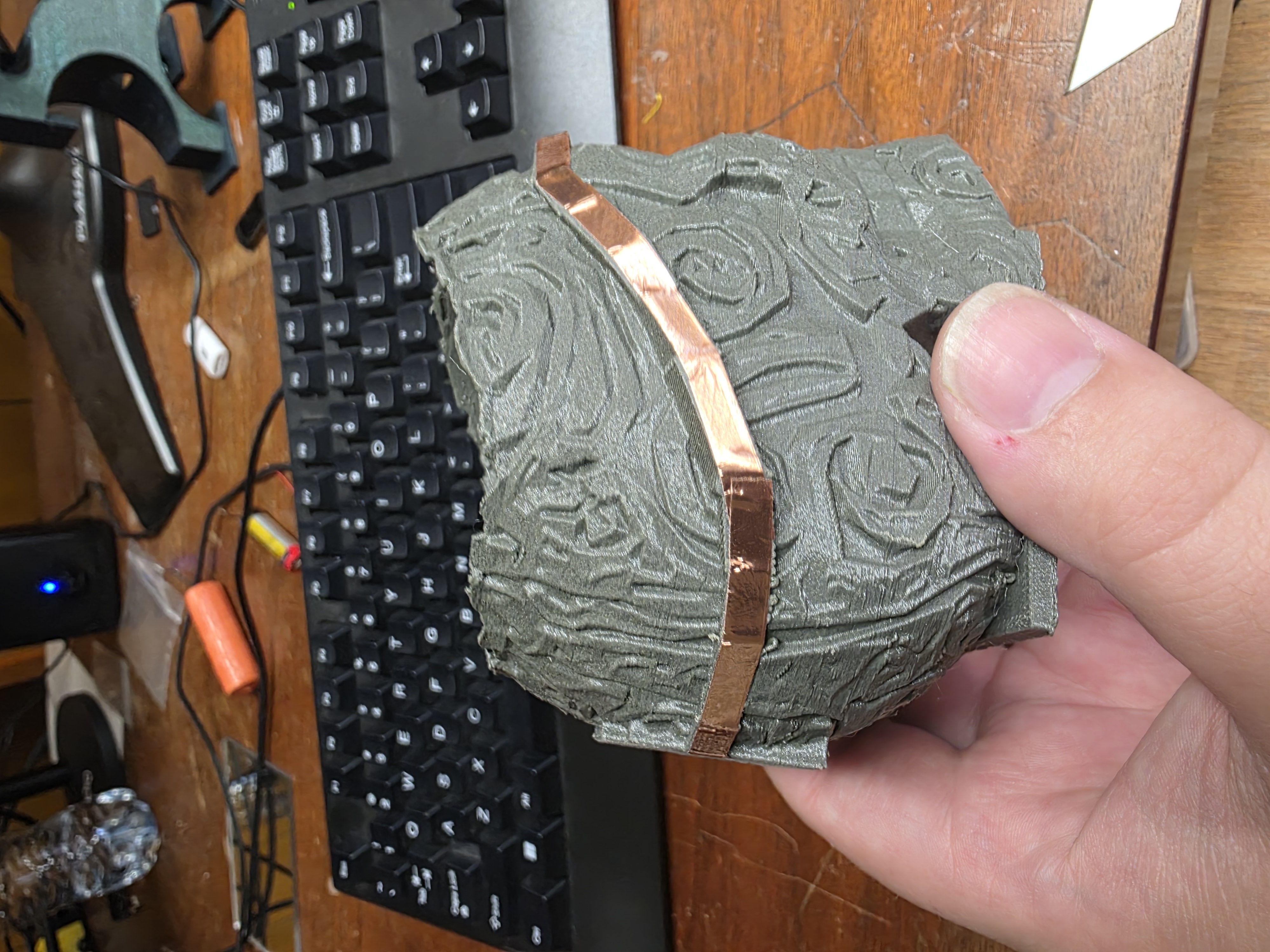
Adding Copper Tape
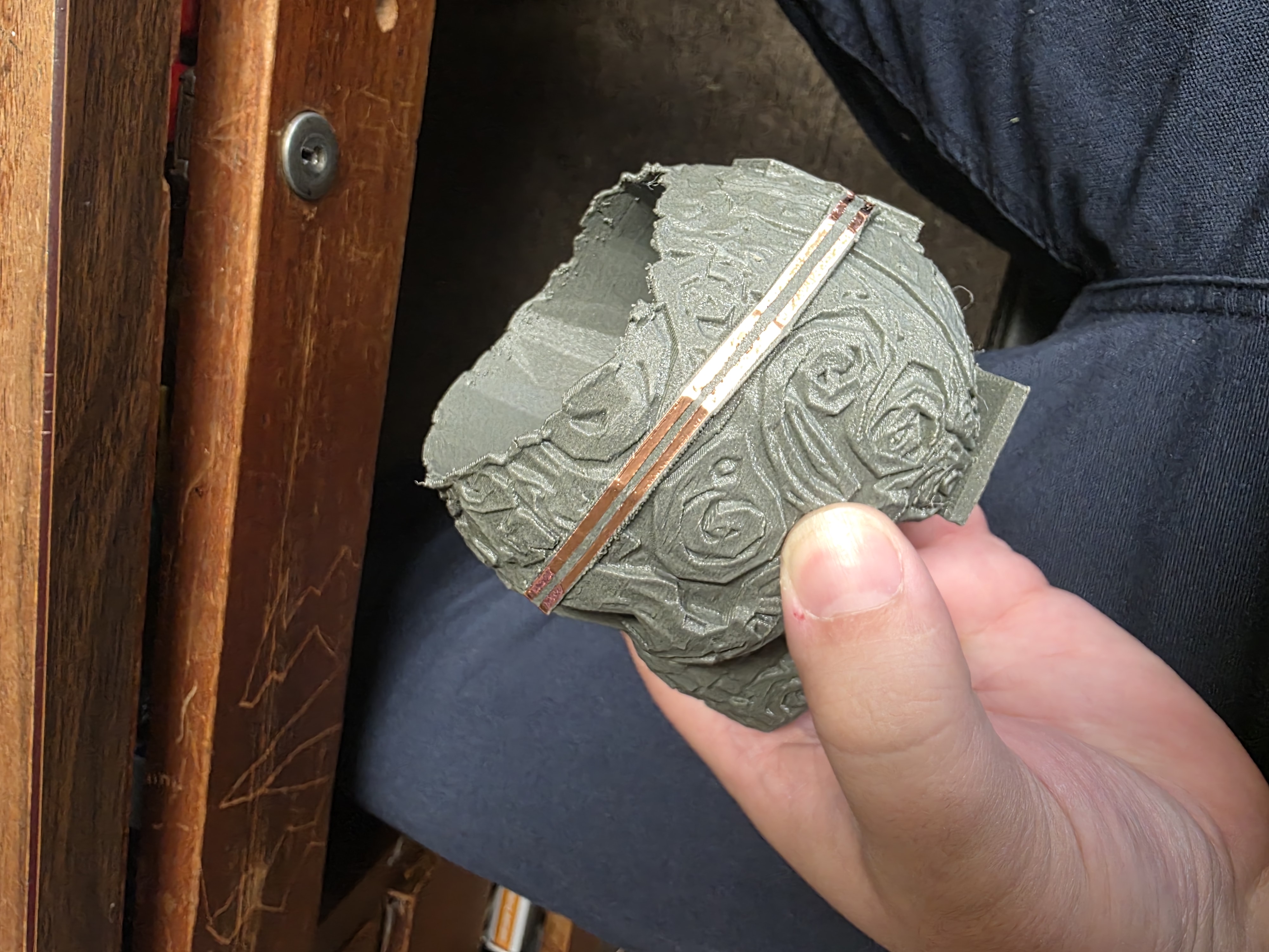
After printing, I sanded the raised traces to smooth them out and help the copper tape stick better. Then I added copper tape over all of the raised paths.
I needed separate power and ground lines, so I used a razor blade to carefully split sections of the copper tape. This created separate conductive paths around the skull.

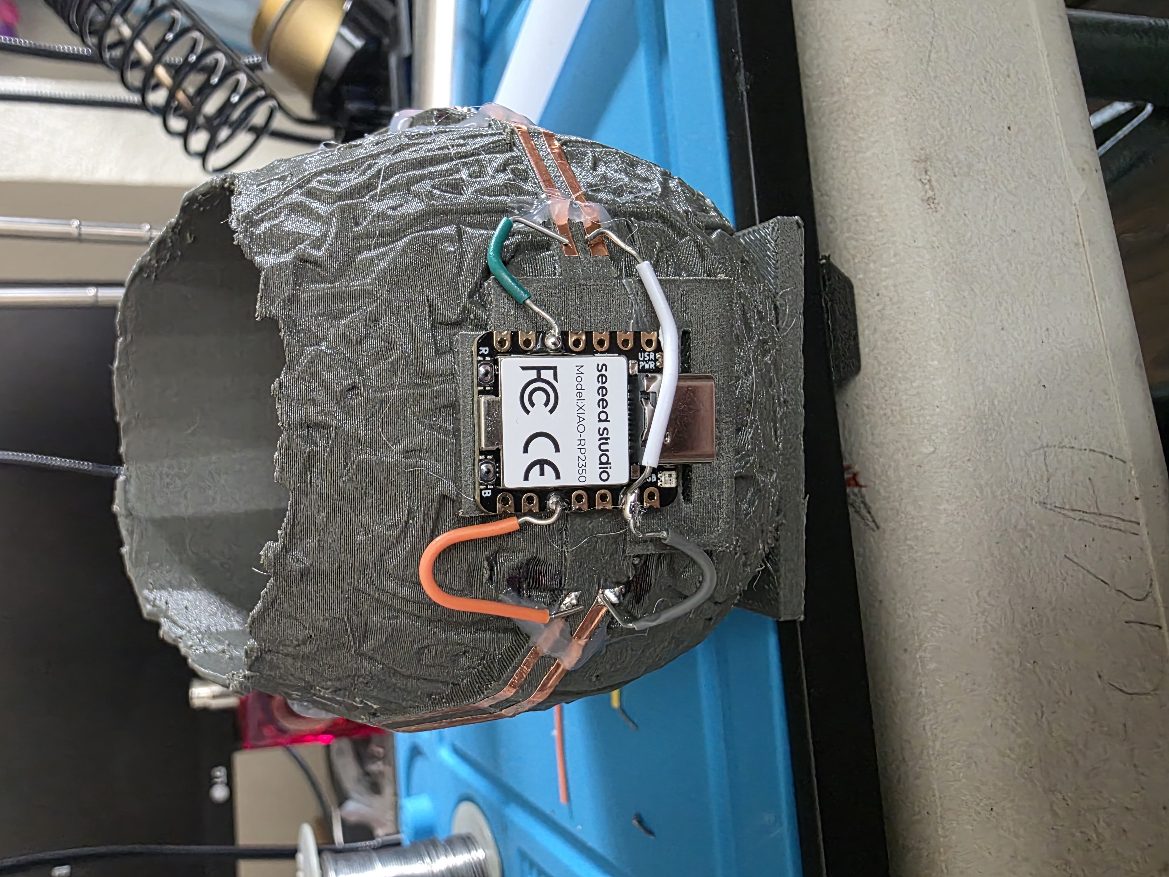
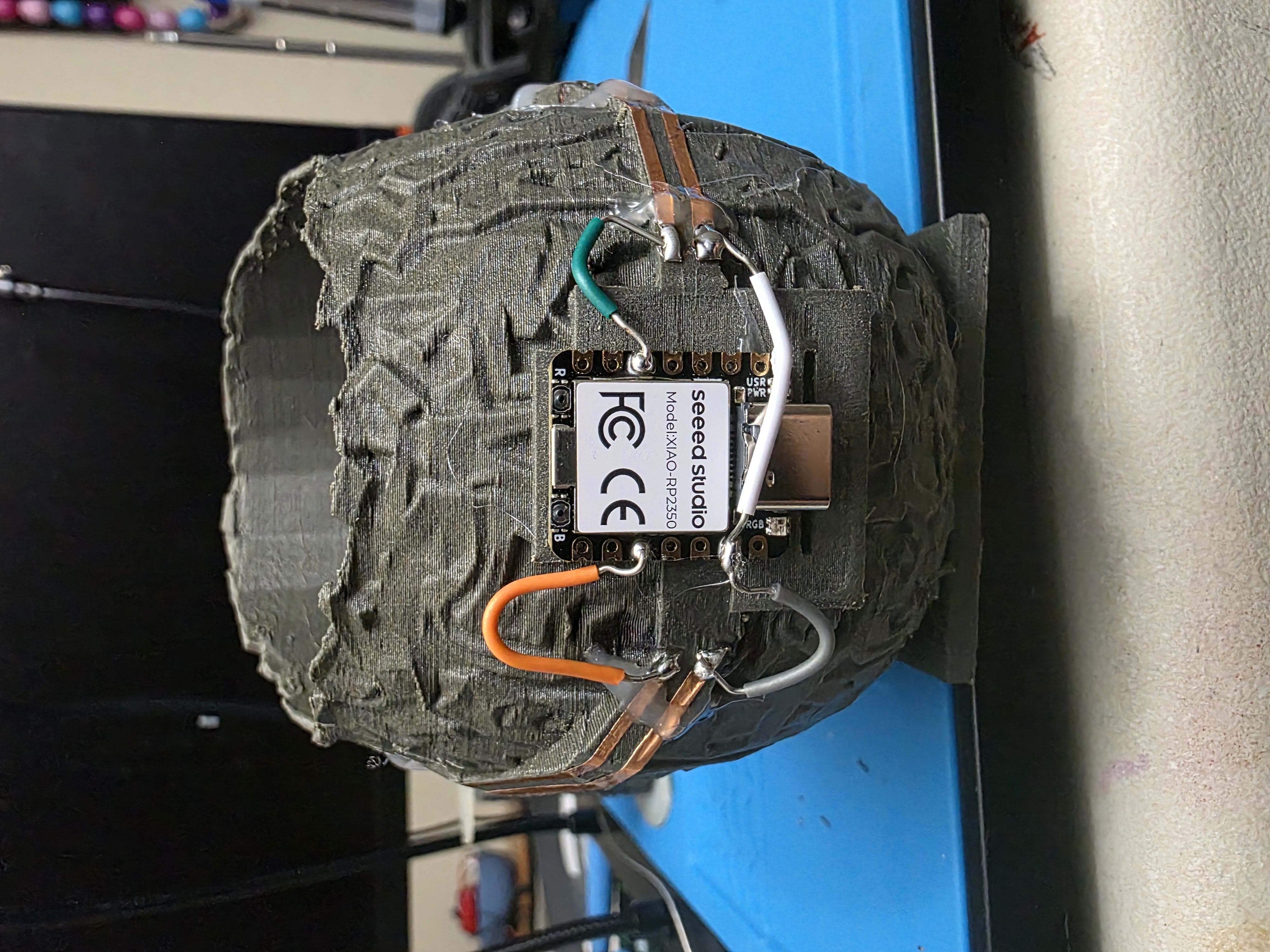
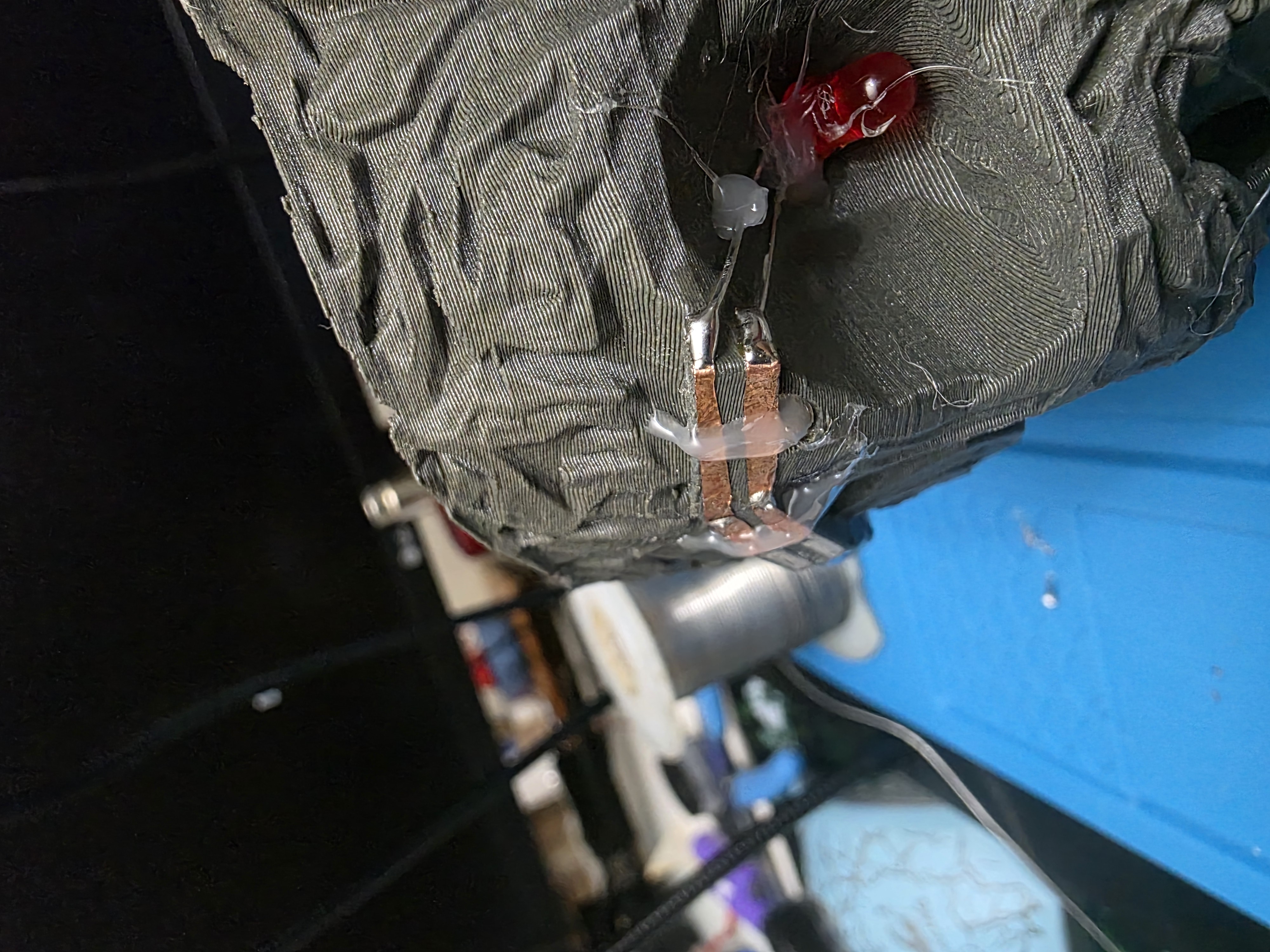
Soldering Problems
Soldering onto copper tape turned out to be harder than I expected. I learned very quickly that holding the soldering iron on the tape too long causes the adhesive to loosen.
Some of the tape lifted while I was soldering corners and overlaps together. To help hold everything in place, I added small straps of hot glue over sections of the copper tape.
The hot glue did not look perfect, but it worked well enough to keep the traces connected.
Arduino IDE Code
I used Arduino IDE to program the RP2350 board. At first I accidentally used regular pin numbers instead of the RP2350 board pin labels, which caused problems.
Once I switched the code to use D4 and D9,
the LEDs started blinking correctly.
int leftLED = D9;
int rightLED = D4;

void setup() {
  pinMode(leftLED, OUTPUT);
  pinMode(rightLED, OUTPUT);
}

void loop() {
  digitalWrite(leftLED, HIGH);
  digitalWrite(rightLED, LOW);
  delay(500);

  digitalWrite(leftLED, LOW);
  digitalWrite(rightLED, HIGH);
  delay(500);
}
Project Files
I originally tried adding all of the STL, 3MF, and Arduino code files directly into my GitLab Pages website. However, GitLab Pages deployment kept failing because the files were too large for the public deployment folder.
To solve that problem, I moved all of the project files into a shared Google Drive folder instead. This folder contains the STL files, 3MF files, sliced files, and Arduino code used for this project.
View and Download Wildcard Week Project Files
Project Video
This video shows the completed skull blinking using the RP2350 and copper tape traces.
What I Learned
- How to simplify heavy 3D models using Blender
- How to create raised traces using Tinkercad
- How copper tape can act as external wiring paths
- How PETG-CF prints behave differently than normal PLA
- How important soldering speed is with adhesive copper tape
- How to use Arduino IDE with the RP2350 board
Final Thoughts
This project ended up being one of the most fun assignments because it mixed electronics, 3D printing, soldering, and experimentation all together into one weird build.
The final skull was not perfect, but it worked exactly how I hoped: blinking LEDs controlled by the RP2350 using raised copper traces on the outside of the skull.