Computer Aided Design
Sketching and modeling the first version of my final project enclosure.
Project Files and Downloads
Here is my file for the STL of the box I made in Tinkercad. I added it as a ZIP file so GitLab would handle it better and so anyone looking at my page can download it and print the enclosure.
I also added the Tinkercad design link. I was trying to add the original editable Tinkercad file before it was exported into an STL, so if someone wanted to edit it they could. I was not fully sure the best way to do that directly, but the Tinkercad link and the STL download are good enough for someone to view the design, copy the link, and print the model.
Original Tinkercad Design:
https://www.tinkercad.com/things/kgz0x2QUuvx-fantabulous-duup
Assignment Goal
For Week 2, the assignment was about computer aided design. I used this week to start planning the physical shape of my final project, which is a smart battery checker and charger. Before jumping into the final build, I needed to think about the enclosure, the screen, the charger boards, the battery connections, and how everything might fit together in one box.
This was still an early idea, so the goal was not to make the perfect final case right away. The goal was to get something modeled, look at the size, and start figuring out what would need to change later. I already knew this design would probably change as the project got farther along, but I needed a real starting point instead of just guessing.
Rough Draft Sketch
I started with a rough paper sketch. This helped me think through the basic layout before I opened any CAD software. I wanted the screen on the front/top where it would be easy to see, and I wanted room for the battery connections, charging modules, wiring, and PCB inside the enclosure.
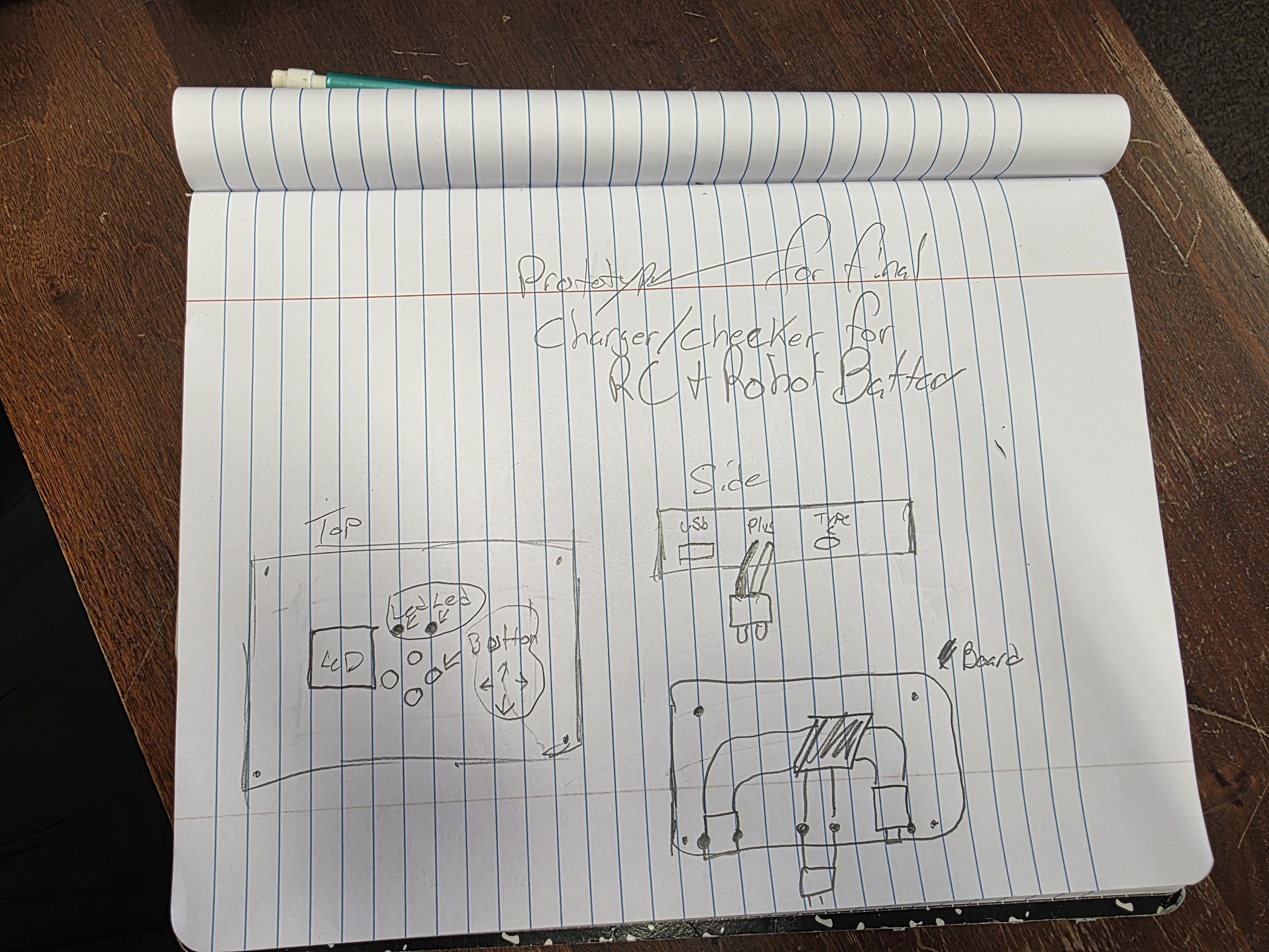
The sketch was not fancy, but it gave me a starting point. It helped me see that the enclosure needed to be more than just a simple box. I had to think about access to ports, screw holes, wire space, and how the project could be opened again if I needed to repair or change something.
Comparing CAD Software
For this week I needed to explain more than just one software, so I compared Tinkercad with FreeCAD and Onshape. All of them can be used for CAD, but they feel pretty different when you actually use them.
Tinkercad is more basic and beginner friendly. It is mostly drag and drop, resize, align, group, and cut holes out of shapes. That made it really good for this assignment because my first design was a simple enclosure box. I did not need a super technical model yet. I just needed to get the shape made, make some cutouts, and see if the idea made sense.
FreeCAD and Onshape are more advanced. They use sketches, constraints, dimensions, and parametric modeling. That means they are better for technical parts where measurements need to be exact and where you may want to go back later and change one dimension without rebuilding the whole model. They are more powerful, but they also take more time to set up and learn.
Since I was making a simple box-style enclosure, I went with Tinkercad for this first version. If I was making a more complicated mechanical part with tighter measurements, then FreeCAD or Onshape would make more sense. For this stage of my final project, Tinkercad was fast, simple, and got the job done.
Why I Used Tinkercad
I used Tinkercad for this first design because it is simple and fast for basic shapes. Since the first enclosure was mostly a box with cutouts, Tinkercad made sense. I could use solid boxes, hole boxes, cylinders, and simple alignment tools without getting slowed down by a more advanced CAD program.
For a first version, I cared more about testing the size and layout than making a perfect production model. Tinkercad let me move quickly and get a model ready to print.
Tinkercad Modeling Process
I started by making the outside box shape. Then I used a smaller box set as a hole to hollow out the inside. This gave me space for the ESP32 screen, charger modules, battery connections, PCB, and wiring.
After the shell was made, I started planning the lid and the mounting holes. I wanted to use brass heat-set threaded inserts so the lid could be screwed down and removed later. That matters because electronics projects usually need opened back up for testing, fixing wires, or changing parts.
I also planned side openings for USB-C charging ports and wiring connections. The first model was not perfect, but it helped me understand the real size of the enclosure and how much space the electronics might need.
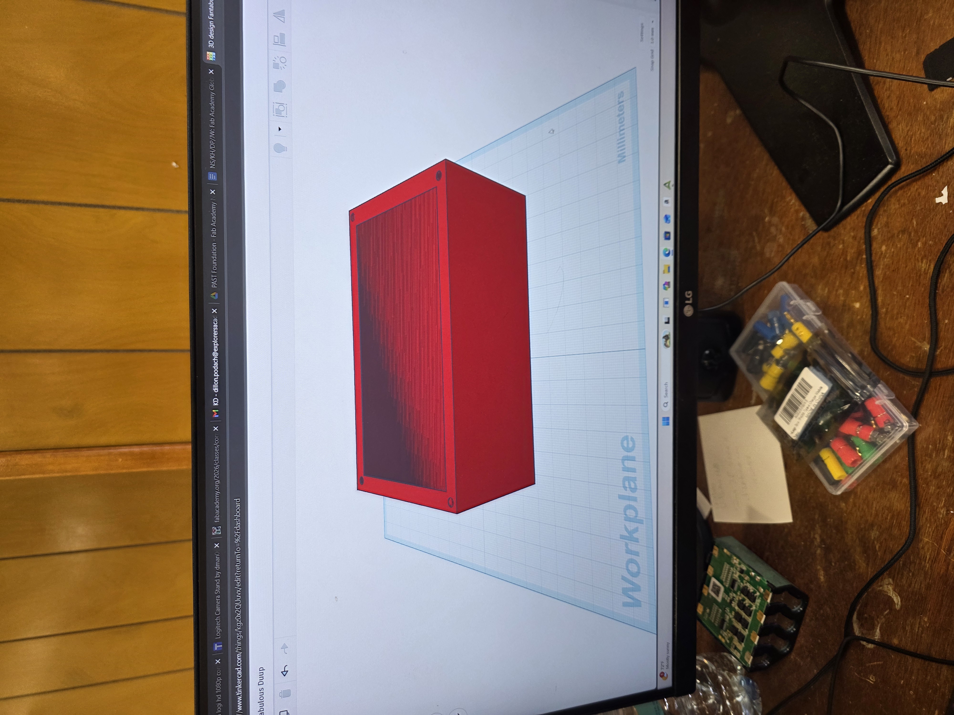
Original Design Files
After modeling the enclosure, I exported it from Tinkercad as an STL file so I could slice it and 3D print it. I also kept the original Tinkercad design link so I could go back and edit it later as the final project changed.
- Original CAD design: Tinkercad enclosure model
- Exported file type: STL
- Download file: week2.zip
- Purpose: early enclosure prototype for my smart battery checker and charger
- Main design idea: box-style enclosure with room for screen, charger boards, PCB, and wiring
3D Printing the Enclosure
After the model was ready, I prepared it for 3D printing. I chose PETG carbon fiber because it is stronger than basic PLA, has a clean dark look, and seemed like a better material for a project enclosure.
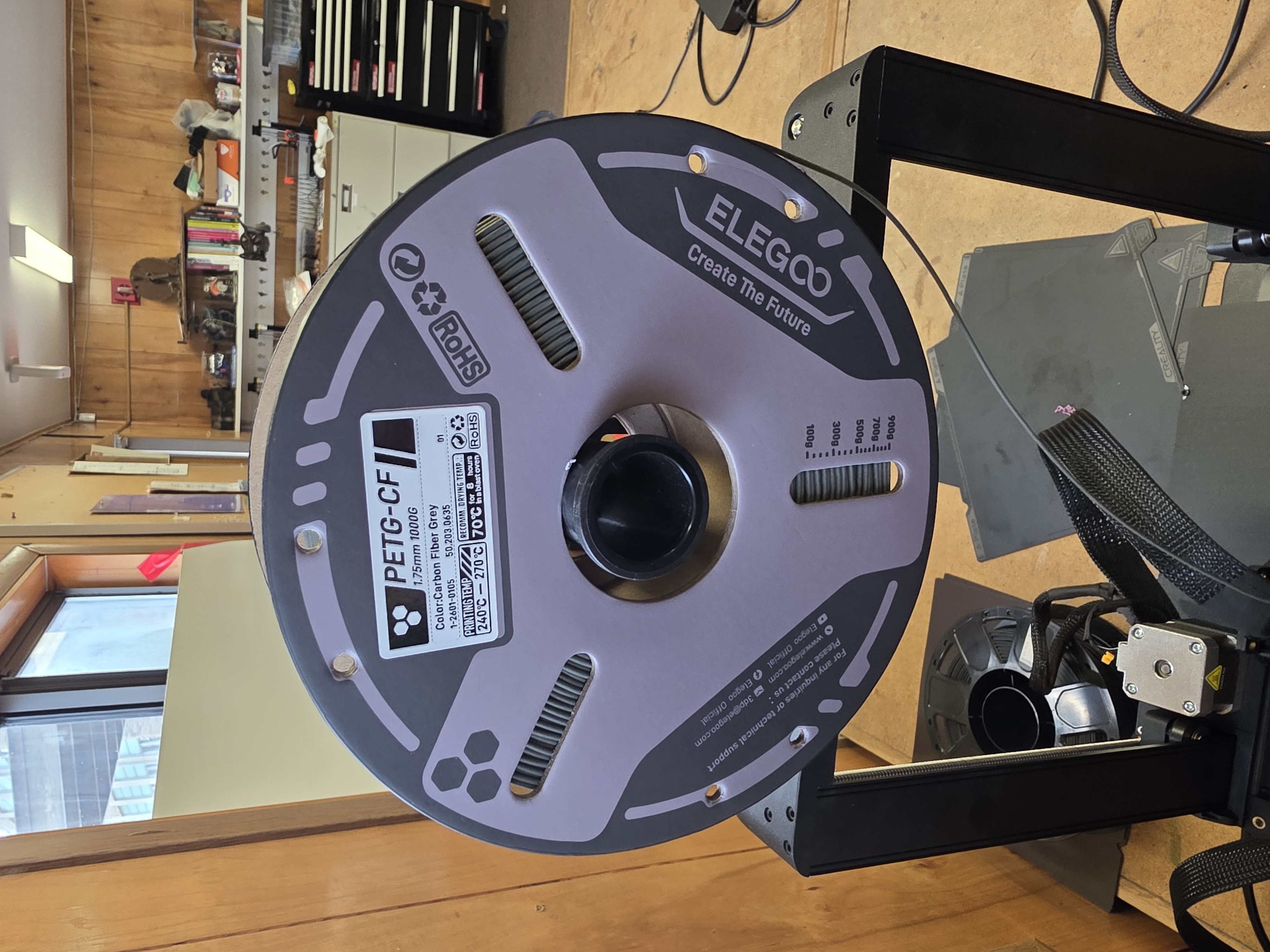
This print was the first physical version of the enclosure. Printing it helped me see the real size of the box and showed me what would need to change. Things like the screen opening, side ports, wire clearance, and insert holes are easier to judge once the part is actually in my hands.
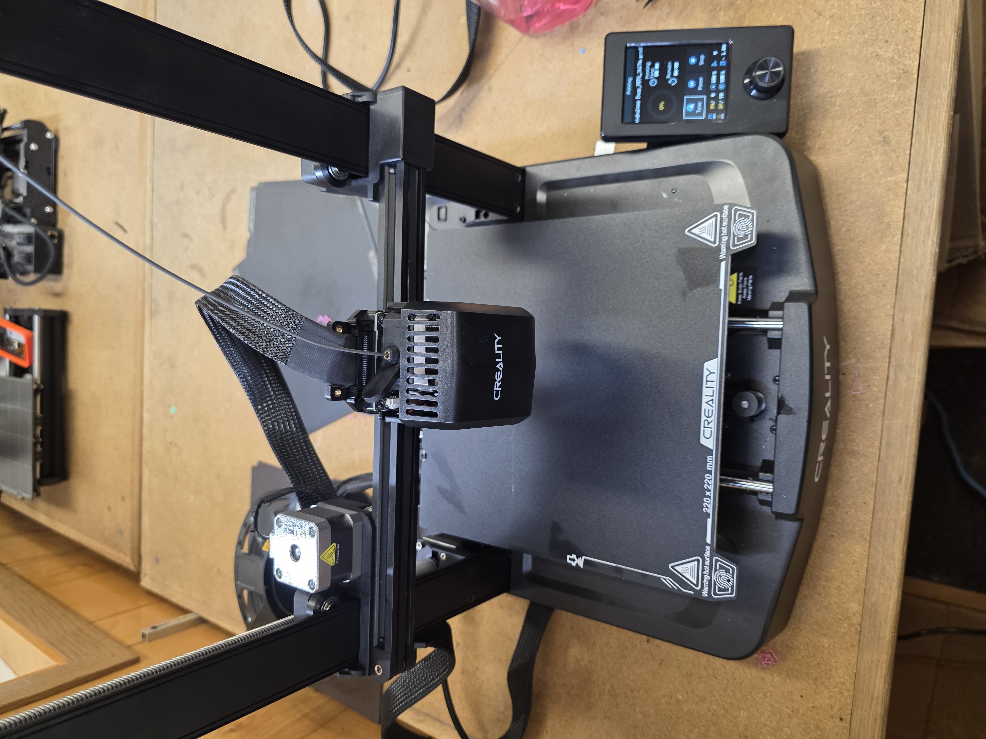
Image Resizing Before GitLab
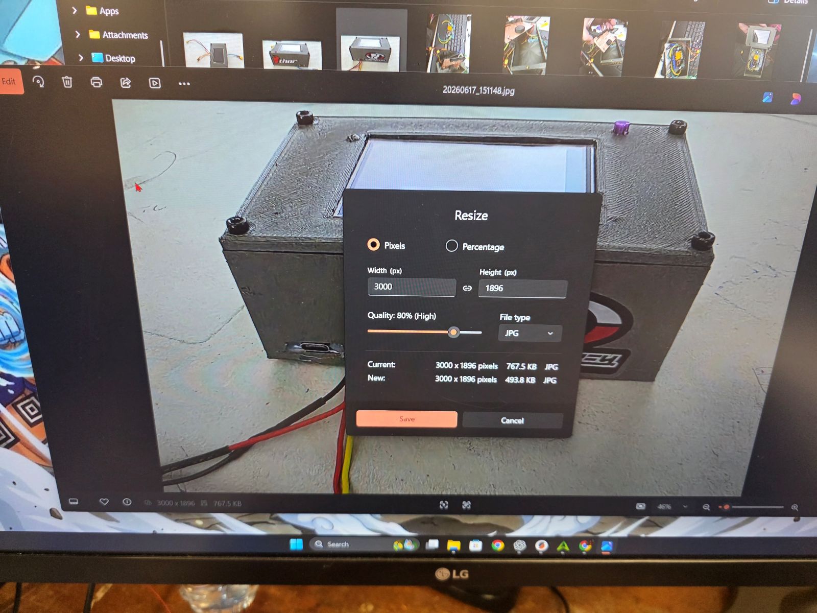
Another thing I worked on for this week was resizing my pictures before putting them on GitLab. Phone pictures are usually huge, and if I upload them straight from my phone, the website can load slow and the files can take up way too much space. So before uploading, I resized the images first.
The size I used was around 1600 pixels wide for the actual image file. That keeps the picture clear, but makes the file smaller and easier for GitLab to handle. Then inside my HTML, I displayed most pictures at about 500 pixels wide so the page looked clean.
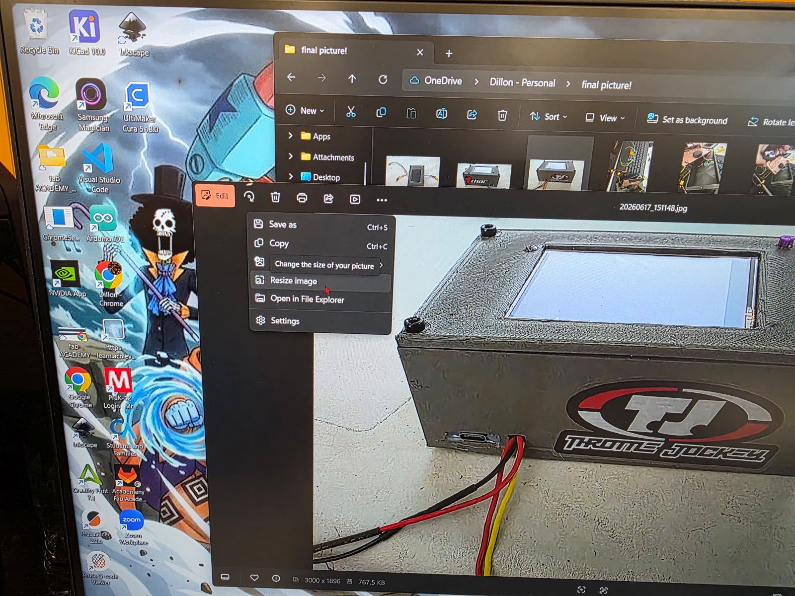
Step 1: Open the Image Resize Tool
First, I opened the picture in the image resize tool. This let me change the image size before uploading it to GitLab.
Step 2: Change the Width
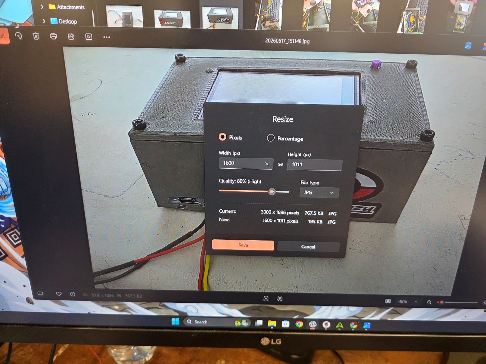
Next, I changed the width to around 1600 pixels. I made sure the picture kept the same shape so it did not get stretched or smashed.
Step 3: Save the Resized Image
After the image was resized, I saved the new version and used that file on my Fab Academy page. This made the image easier to upload and helped keep my website from being too slow.
In my HTML, I still control how big the image looks on the page by using the width number in the image tag. For example, the image file can be 1600 pixels wide, but I can show it on the page at 500 pixels wide.
<img src="../images/example.jpg" width="500" alt="Example resized image">What I Learned
This week helped me understand that CAD is not just about making something look cool on the screen. It is about thinking through the real object before building it. Even a simple box needs planning because electronics need space, wires need room, and the case needs to be opened later if something needs fixed.
I also learned that different CAD programs are better for different jobs. Tinkercad was the right choice for this simple early enclosure because it was fast and easy. FreeCAD and Onshape are better for more advanced technical designs, but for this first version I did not need all of that yet.
I also learned that documentation matters. Resizing images before GitLab keeps the website cleaner, faster, and easier to manage. That is something I will keep doing for the rest of my Fab Academy pages.