Week 4 - Embedded Programming
Temperature controlled cooling system using an Arduino.
Assignments
Group Assignment
- Demonstrate and compare the toolchains and development workflows for available embedded architectures.
Individual Assignment
- Read a microcontroller data sheet.
- Program a microcontroller development board to interact and communicate.
Group Assignment - Comparing Embedded Toolchains
For the group assignment, we compared different embedded programming toolchains and workflows. The main idea was to see that not every microcontroller is programmed the same way, even if the final goal is still uploading code to a board and making hardware do something.
We looked at different embedded architectures and boards that were available in the lab, including Arduino-style boards and newer microcontroller boards like the Seeed XIAO boards. We talked about how each board has its own chip, pinout, upload method, libraries, drivers, and sometimes even different USB behavior.
One workflow we compared was using the Arduino IDE. This was the easiest one for me to understand at first because I could select the board, select the COM port, write code, and upload it. Arduino IDE also makes libraries easier to install, which helped when working with sensors, LCDs, OLEDs, and other modules.
We also compared that to other development workflows like using board packages, different cores, and more advanced coding tools. Some boards need extra board manager URLs, some need drivers, and some need to be put into bootloader mode before they show up correctly. That was one of the biggest differences I noticed.
The big comparison points were:
- How the board connects to the computer.
- How the correct board package or core gets installed.
- How libraries are added.
- How code is compiled and uploaded.
- How serial monitor is used for testing and debugging.
- How pin names can change between boards.
- How some boards are 5V logic and some are 3.3V logic.
This helped me understand that embedded programming is not just code. The toolchain matters a lot. If the wrong board is selected, the wrong port is selected, or the wrong pin names are used, the code can be fine but the board still will not work.
For my own work this week, I used the Arduino Uno R3 because it was part of the starter kit and was a good board to learn on. Later on, I also worked with the Seeed RP2350 and ESP32-C3 boards, and those made this group assignment make even more sense because the workflow changed depending on the architecture.
Individual Assignment - Arduino Cooling System
For Week 4, I worked on embedded programming using an Arduino Uno R3 starter kit. I built a small automatic cooling system. The idea was simple: when the temperature sensor gets warm, the red LED turns on and the fan motor turns on. When the sensor cools down, the fan turns off and the green LED turns on.
This project helped me see how software and hardware work together. The Arduino reads an input from the TMP36 temperature sensor, makes a decision in the code, and then controls output devices like LEDs, a motor, and an LCD screen.
Components Used
- Arduino Uno R3
- TMP36 temperature sensor
- Red LED
- Green LED
- Current limiting resistors
- Small DC motor/fan
- 9V battery connector
- IRF520 MOSFET motor driver module
- 16x2 LCD display
- Potentiometer for LCD contrast
- Breadboard and jumper wires
Microcontroller and Sensor Information
The Arduino Uno R3 is based on the ATmega328P microcontroller. It operates at 5V, has 14 digital input/output pins, 6 analog input pins, and runs at 16 MHz. This made it a good board for this project because I needed analog input for the TMP36 sensor and digital output pins for the LEDs, LCD, and motor control.
The TMP36 is an analog temperature sensor. It outputs a voltage that changes with temperature. The Arduino reads that voltage on an analog pin and the code converts the reading into degrees Celsius. The important part I had to understand was that the sensor reading is not just a temperature number right away. It has to be converted from analog value, to voltage, and then to temperature.
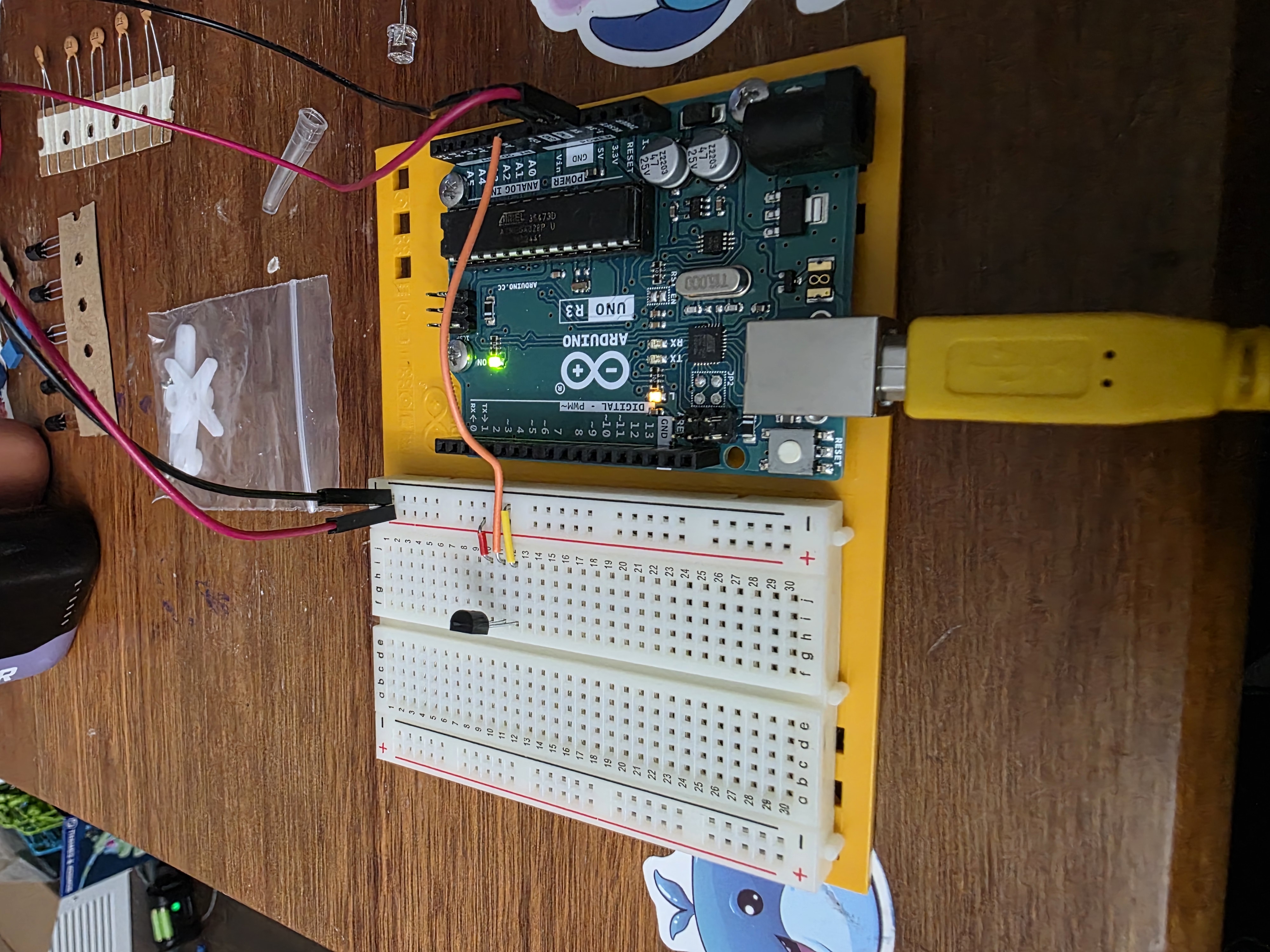
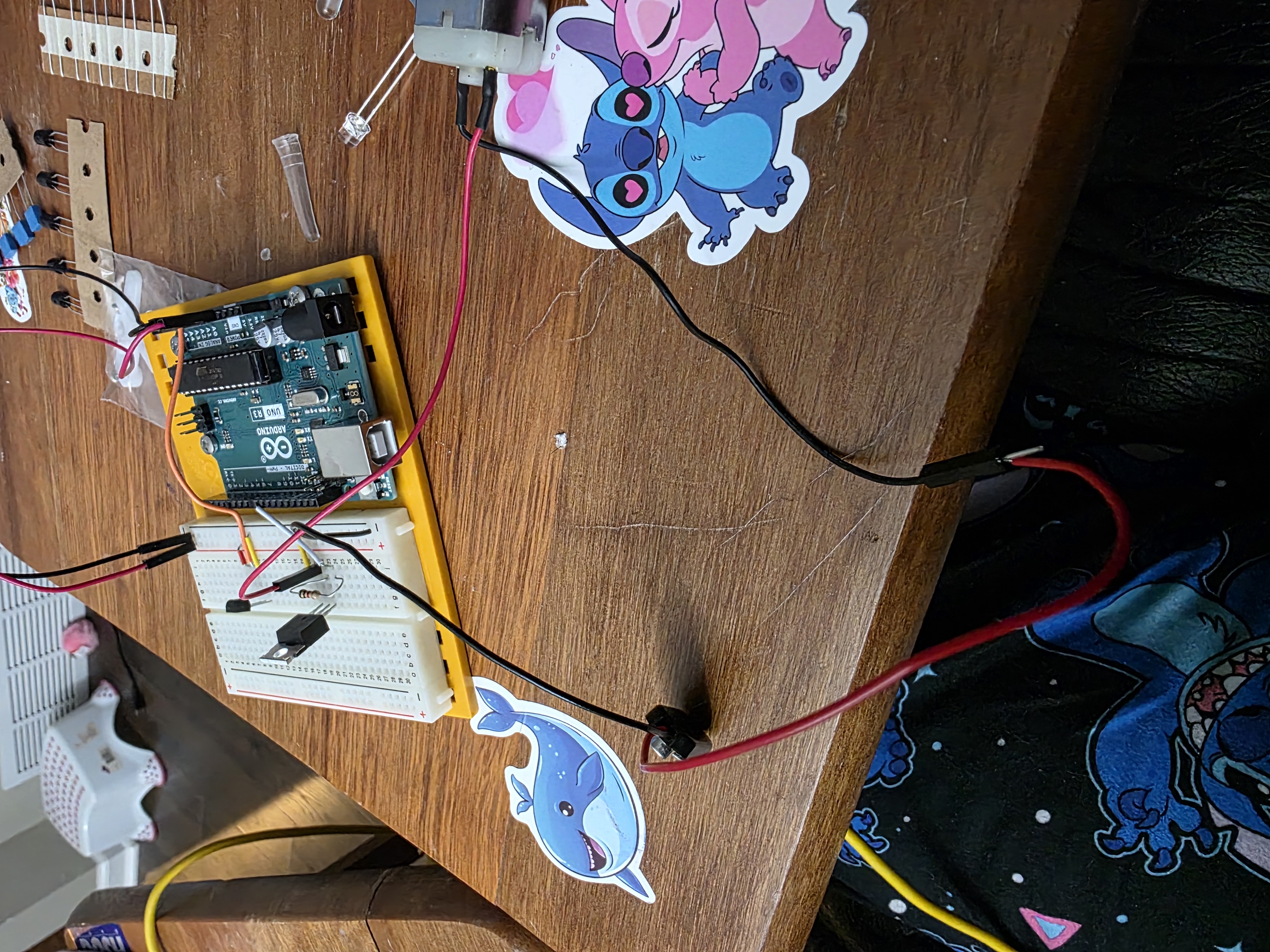
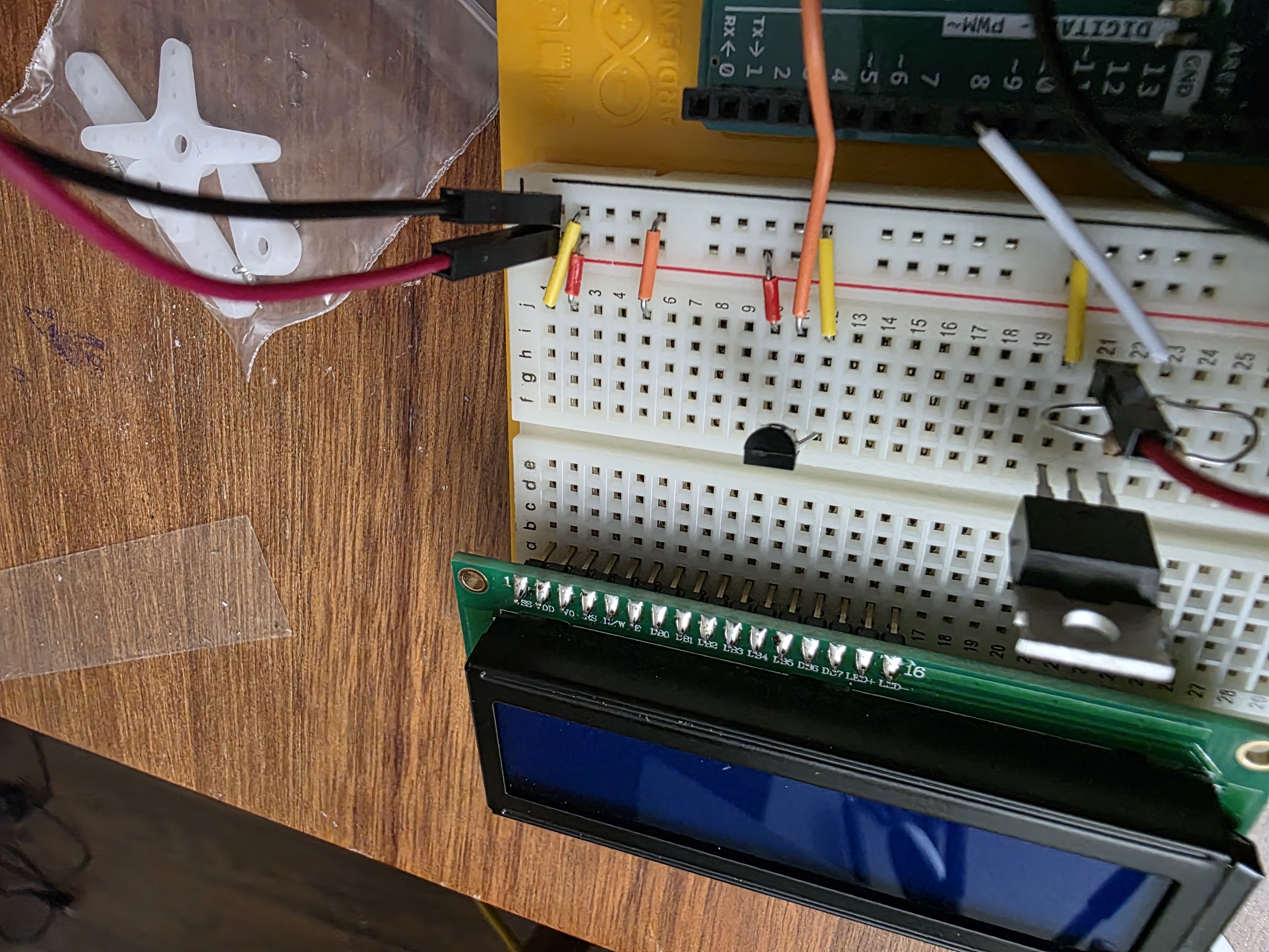
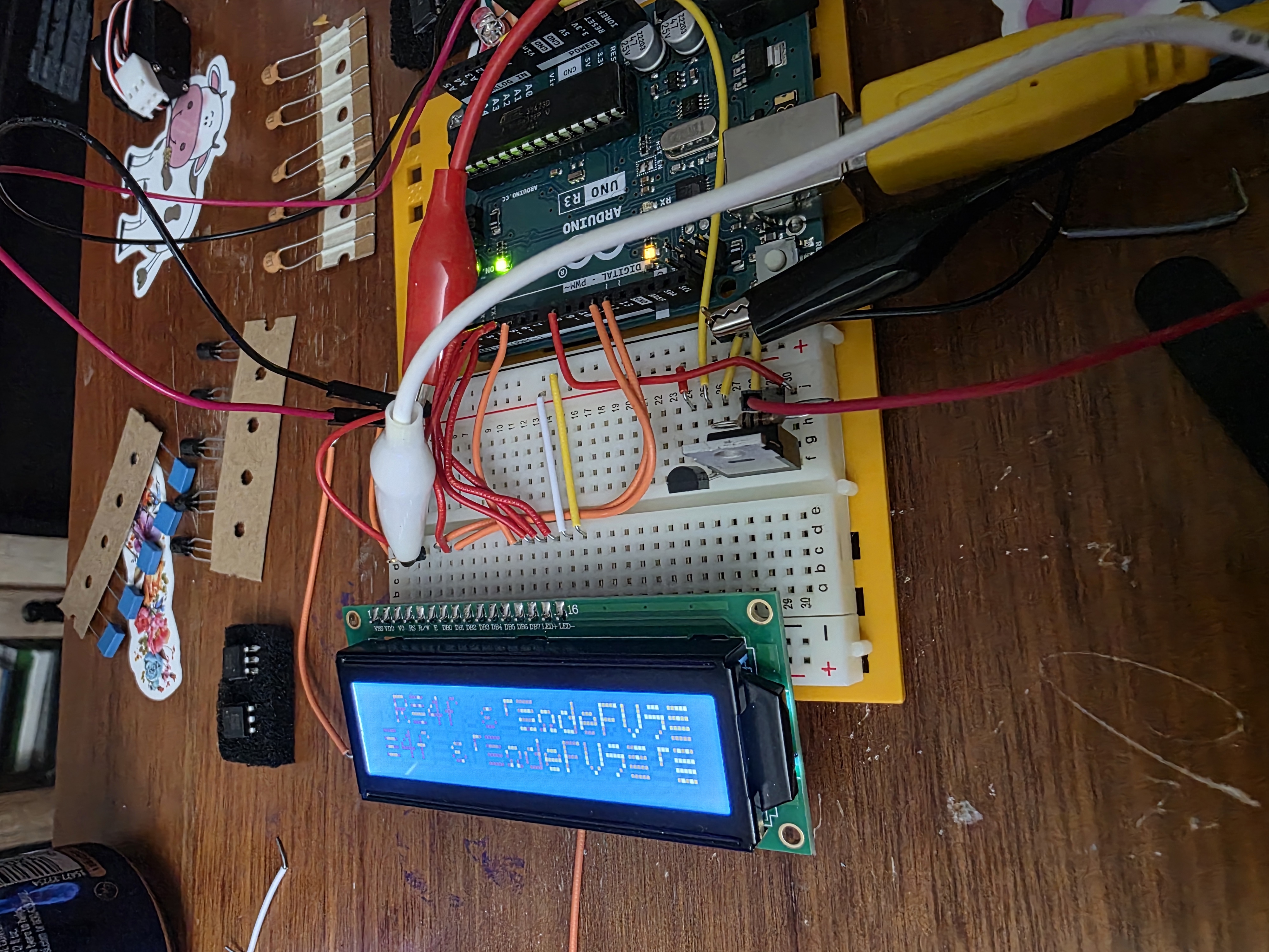
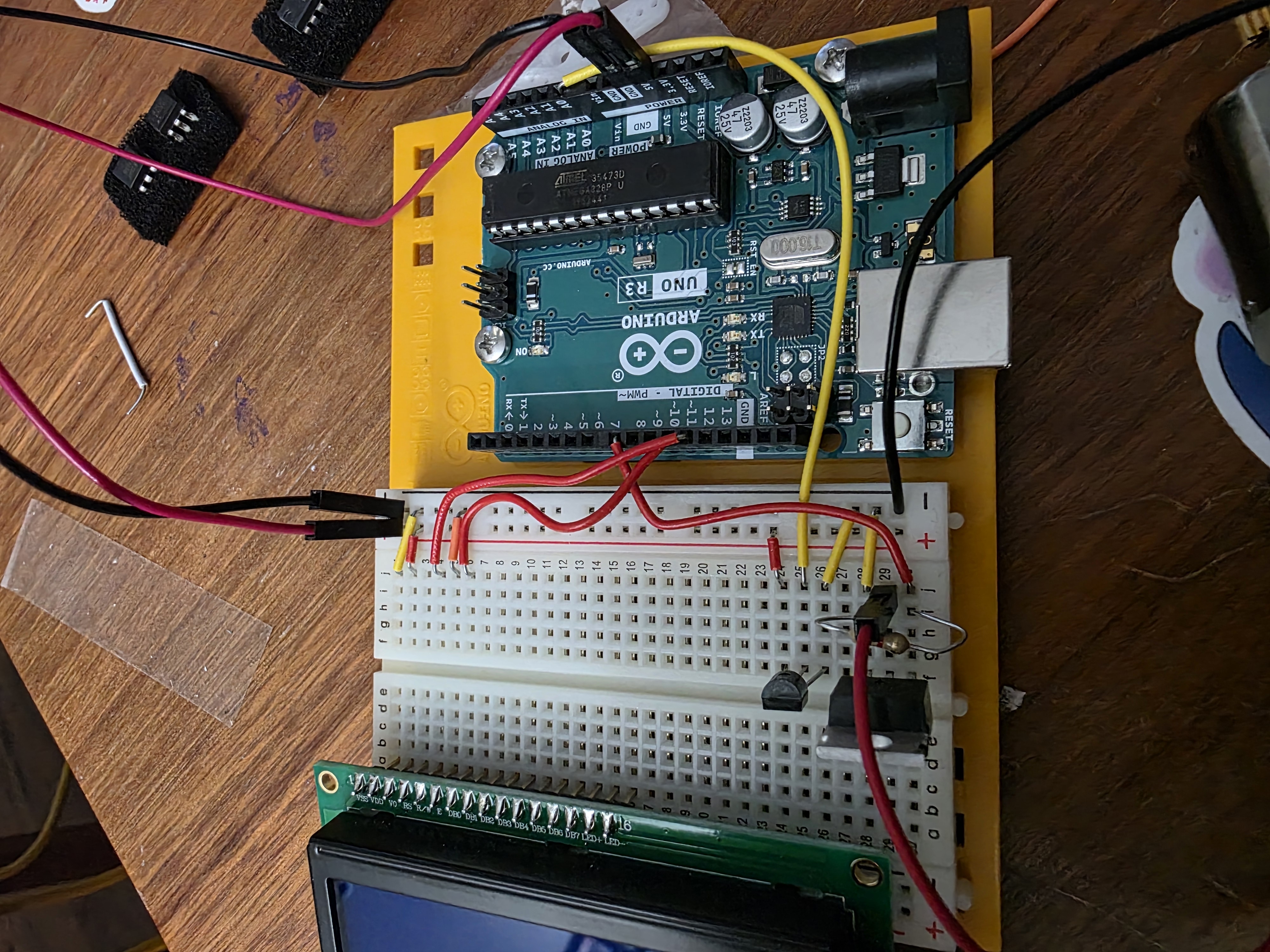
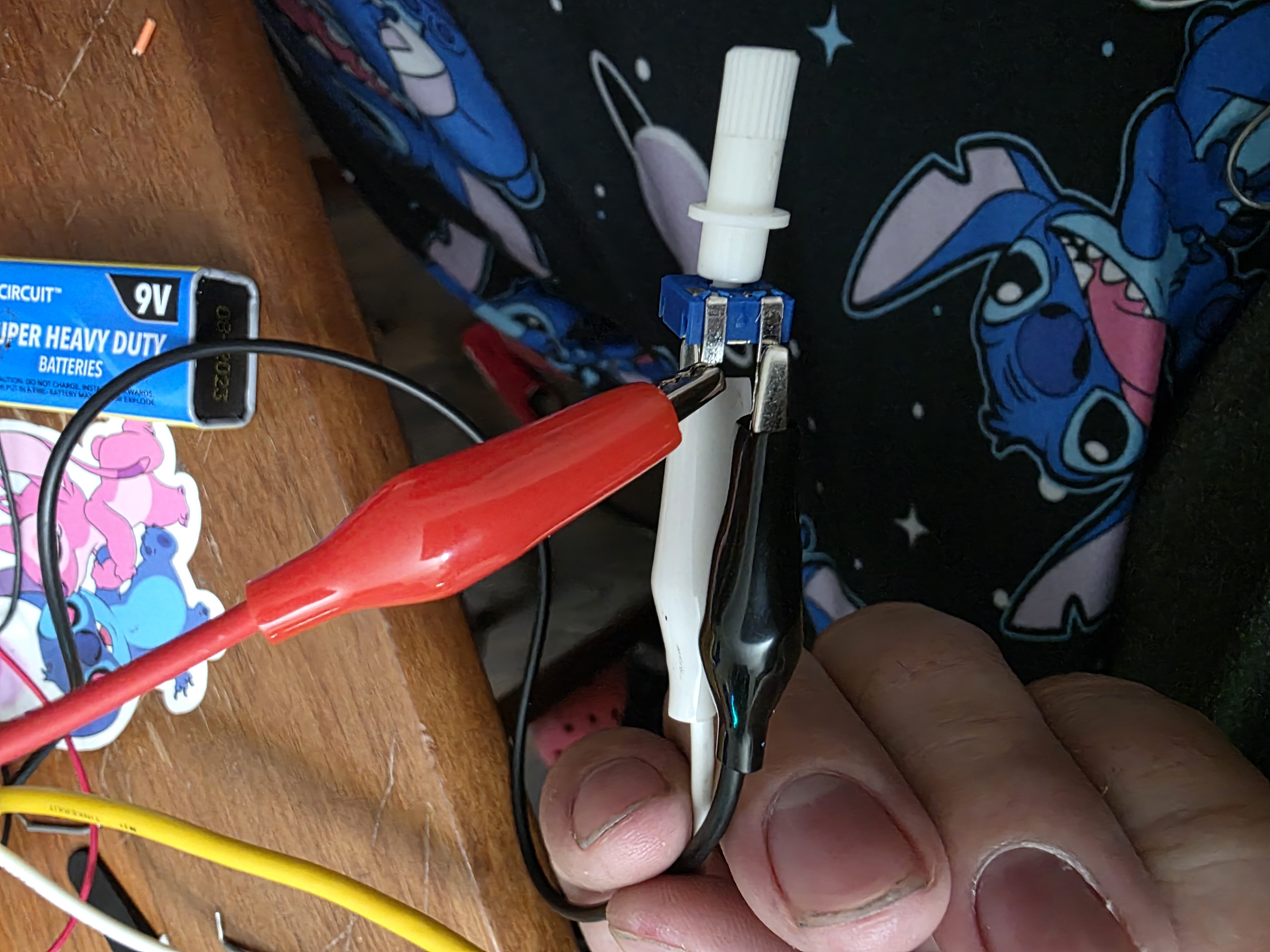
Project Images
These pictures show the process of wiring, testing, programming, and debugging the embedded cooling system.


How the Code Works
The code starts by loading the LiquidCrystal library so the Arduino can control the LCD screen. Then the code assigns pin numbers for the TMP36 temperature sensor, red LED, green LED, and fan. In the setup section, the LCD is started and the LED and fan pins are set as outputs.
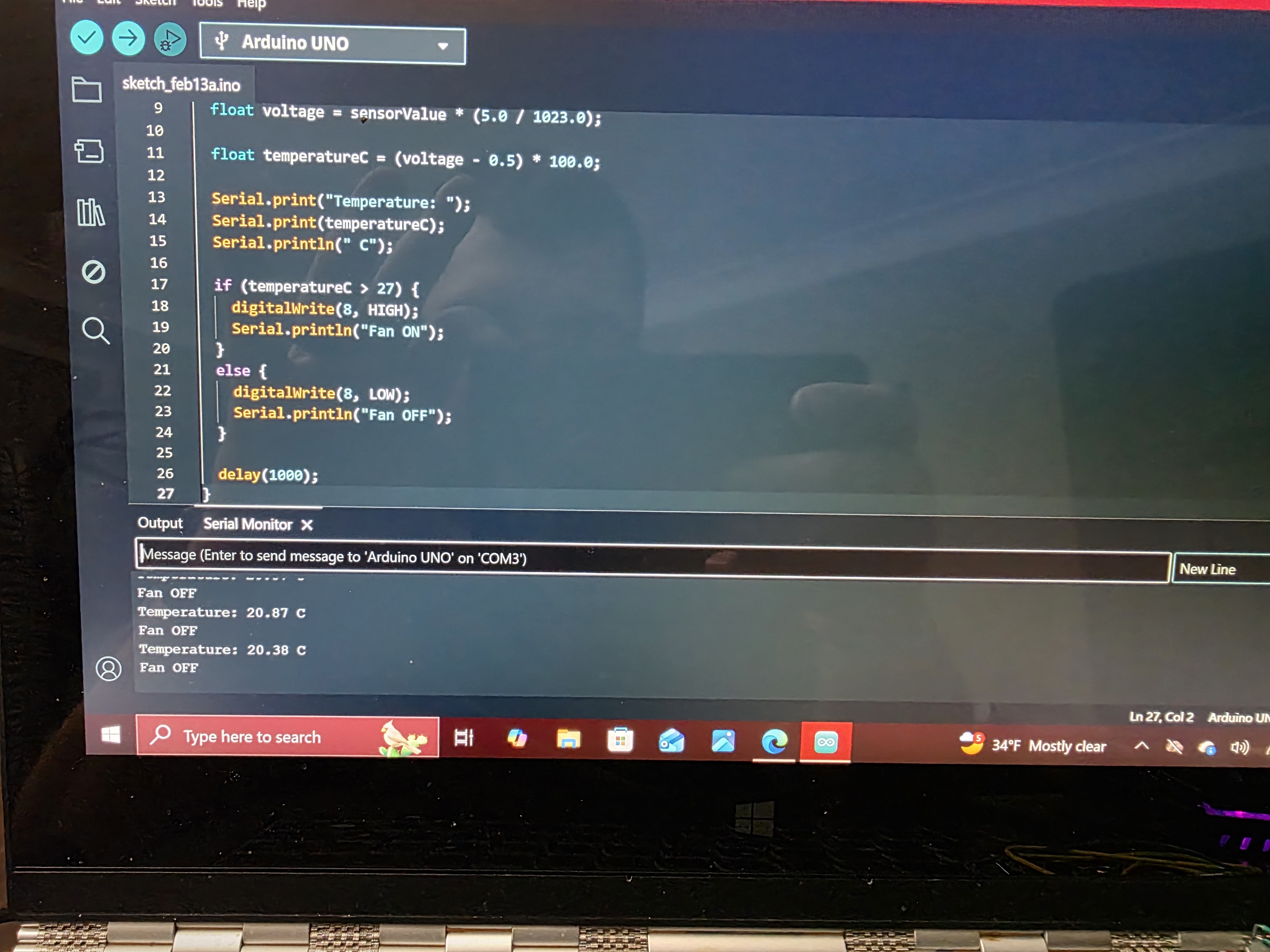
Inside the main loop, the Arduino reads the TMP36 sensor using analogRead(). The analog
reading is converted into voltage. Then the voltage is converted into temperature. Since the TMP36 has
a 500 mV offset and changes by 10 mV per °C, the code subtracts 0.5 volts and multiplies by 100 to get
degrees Celsius.
After calculating the temperature, the code compares it to a threshold. If the temperature is above the threshold, the red LED turns on, the fan turns on, and the LCD says the system is hot. If the temperature is below the threshold, the green LED turns on, the fan turns off, and the LCD says the system is cool.
Source Code
This is the full Arduino source code for my temperature controlled cooling system.
#include <LiquidCrystal.h>

// LCD pins: RS, E, D4, D5, D6, D7
LiquidCrystal lcd(12, 11, 5, 4, 3, 2);

// Pin setup
const int tempPin = A0;
const int redLedPin = 8;
const int greenLedPin = 7;
const int fanPin = 9;

// Temperature limit in Celsius
const float hotTemp = 30.0;

void setup() {
  pinMode(redLedPin, OUTPUT);
  pinMode(greenLedPin, OUTPUT);
  pinMode(fanPin, OUTPUT);

  lcd.begin(16, 2);
  lcd.clear();

  lcd.setCursor(0, 0);
  lcd.print("Auto Cooler");
  lcd.setCursor(0, 1);
  lcd.print("Starting...");
  delay(1500);
}

void loop() {
  int sensorValue = analogRead(tempPin);

  float voltage = sensorValue * (5.0 / 1023.0);
  float temperatureC = (voltage - 0.5) * 100.0;

  lcd.clear();
  lcd.setCursor(0, 0);
  lcd.print("Temp: ");
  lcd.print(temperatureC);
  lcd.print(" C");

  if (temperatureC >= hotTemp) {
    digitalWrite(redLedPin, HIGH);
    digitalWrite(greenLedPin, LOW);
    digitalWrite(fanPin, HIGH);

    lcd.setCursor(0, 1);
    lcd.print("HOT Fan ON");
  } else {
    digitalWrite(redLedPin, LOW);
    digitalWrite(greenLedPin, HIGH);
    digitalWrite(fanPin, LOW);

    lcd.setCursor(0, 1);
    lcd.print("COOL Fan OFF");
  }

  delay(500);
}
Debugging and Testing
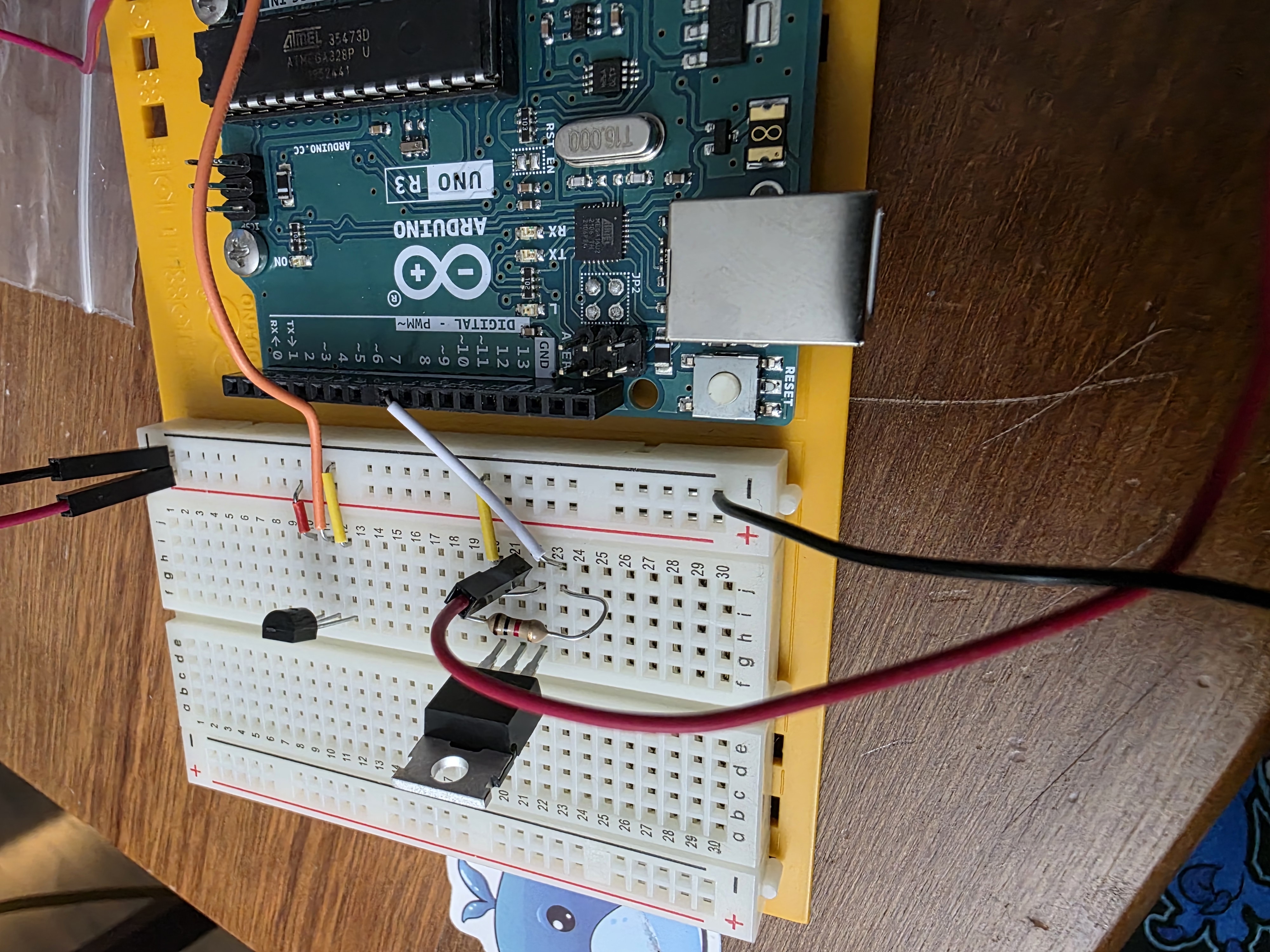
This project took some trial and error. I had to check the wiring several times because one wrong connection on the breadboard can make the sensor, LCD, LED, or motor act wrong. I also had to make sure the TMP36 was facing the correct direction because it looks similar to a transistor but works differently.
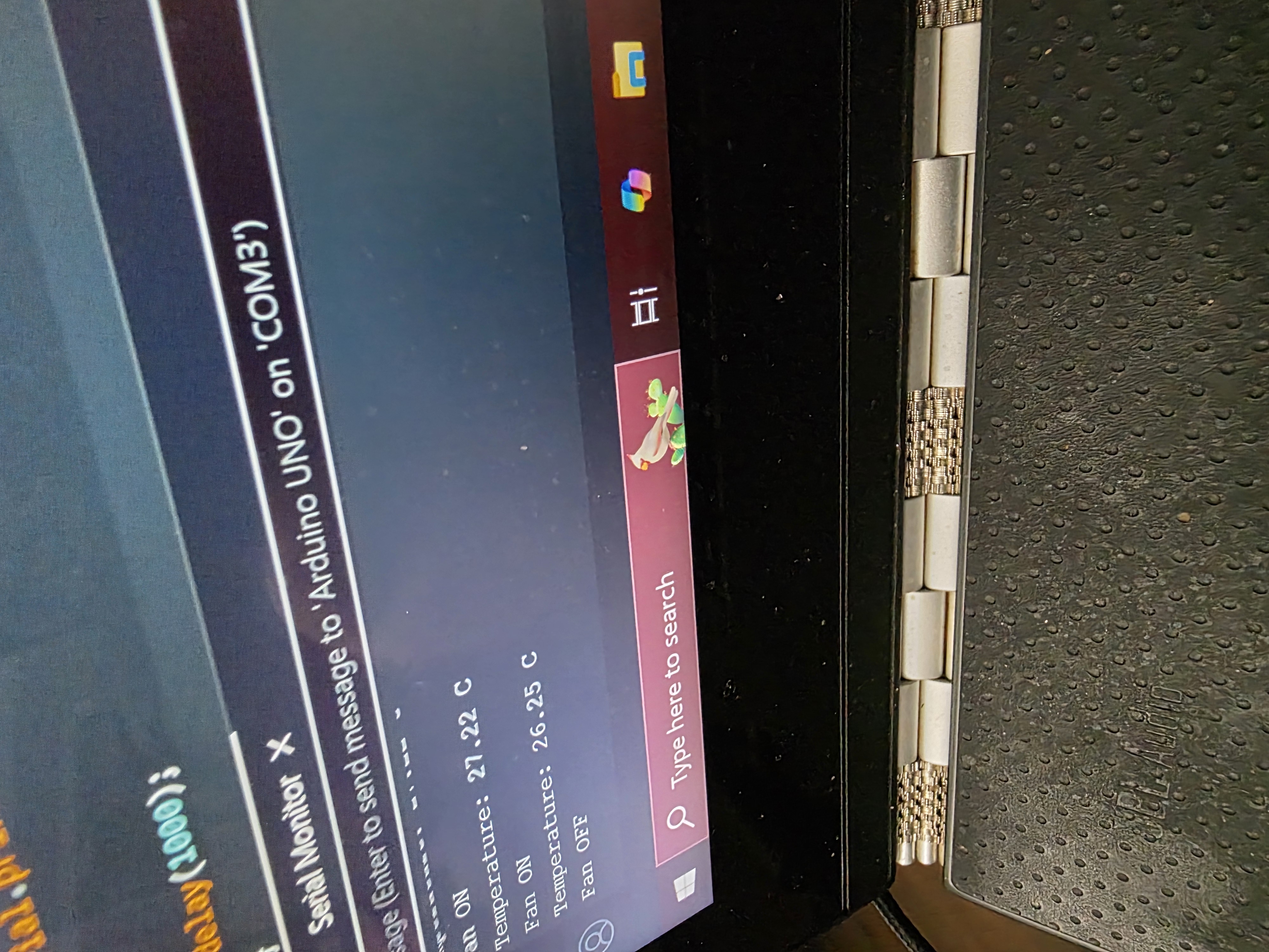
I tested the system by touching or holding the TMP36 sensor to warm it up. When the sensor temperature increased, the LCD showed the temperature, the red LED turned on, and the fan motor turned on. When the sensor cooled back down, the green LED turned on and the fan shut off.
What I Learned
This week helped me understand how embedded programming connects inputs and outputs. The TMP36 sensor was the input, and the LEDs, LCD, and motor were the outputs. The Arduino code connected everything together by reading the sensor and deciding what the outputs should do.
I also learned that the programming workflow matters. Selecting the correct board, selecting the right port, installing the right libraries, and understanding the pinout are all part of embedded programming. It is not just writing code and hoping it works.
Final Thoughts
This assignment helped me build a better understanding of how a microcontroller can read real-world data and control hardware. It also gave me a good starting point for later weeks where I moved from the Arduino Uno to other boards and started designing my own PCB.