Week 9 - Input Devices
This week I added inputs to my RP2350 board so the system could read real-world values.
Assignments
Group Assignment
- Probe an input device's analog levels and digital signals.
Individual Assignment
- Measure something by adding a sensor to a microcontroller board that I designed and reading it.
Group Assignment - Probing Input Signals
For the group assignment, we had to probe an input device and look at its analog levels and digital signals. The main point was to stop just trusting the code and actually see what the input device was sending to the microcontroller.
On this project, my main input devices were the TMP36 temperature sensor and the potentiometer. The TMP36 gives an analog voltage that changes based on temperature. The potentiometer also gives an analog voltage, but that voltage changes when I turn the knob.
We used test equipment in the lab to check the signals and understand what was happening. For an analog input, the voltage does not just turn on and off. It moves between low and high values. That is different from a digital signal, which is usually either LOW or HIGH.
The potentiometer was a good example of an analog input because as I turned the knob, the signal changed smoothly. The microcontroller reads that changing voltage as a number. Then I used that number in code to control the motor speed.
The TMP36 was also analog. When the temperature changed, the voltage changed, and the RP2350 read that value on an analog pin. Then the code converted the analog reading into Fahrenheit so I could display it on the OLED.
This group assignment helped me understand that input devices are not magic. They are just sending voltage or signals to the microcontroller, and the microcontroller reads those values and makes decisions from them.
Individual Assignment - Adding Inputs to My Board
For my individual assignment, I measured something using a sensor connected to a microcontroller board that I designed. I used the TMP36 temperature sensor to measure temperature and the potentiometer as a control knob for motor speed.
This project started out simple with just a motor and LEDs. At first, the system could turn the motor on and switch between a red and green LED. Then I kept building it up. I added the OLED screen so I could see what was happening instead of guessing. After that, I added the potentiometer speed knob so the motor speed could be controlled by an input.
So Week 9 was really about the input side of the project. The board was not just blinking LEDs anymore. It was reading real values from sensors and using those values to control the rest of the system.
Input Devices Used
- TMP36 temperature sensor: measured temperature as an analog voltage.
- Potentiometer: acted like a speed knob for the motor.
- RP2350 analog pins: read the sensor and knob values.
- OLED display: showed the temperature, limit, and motor status.
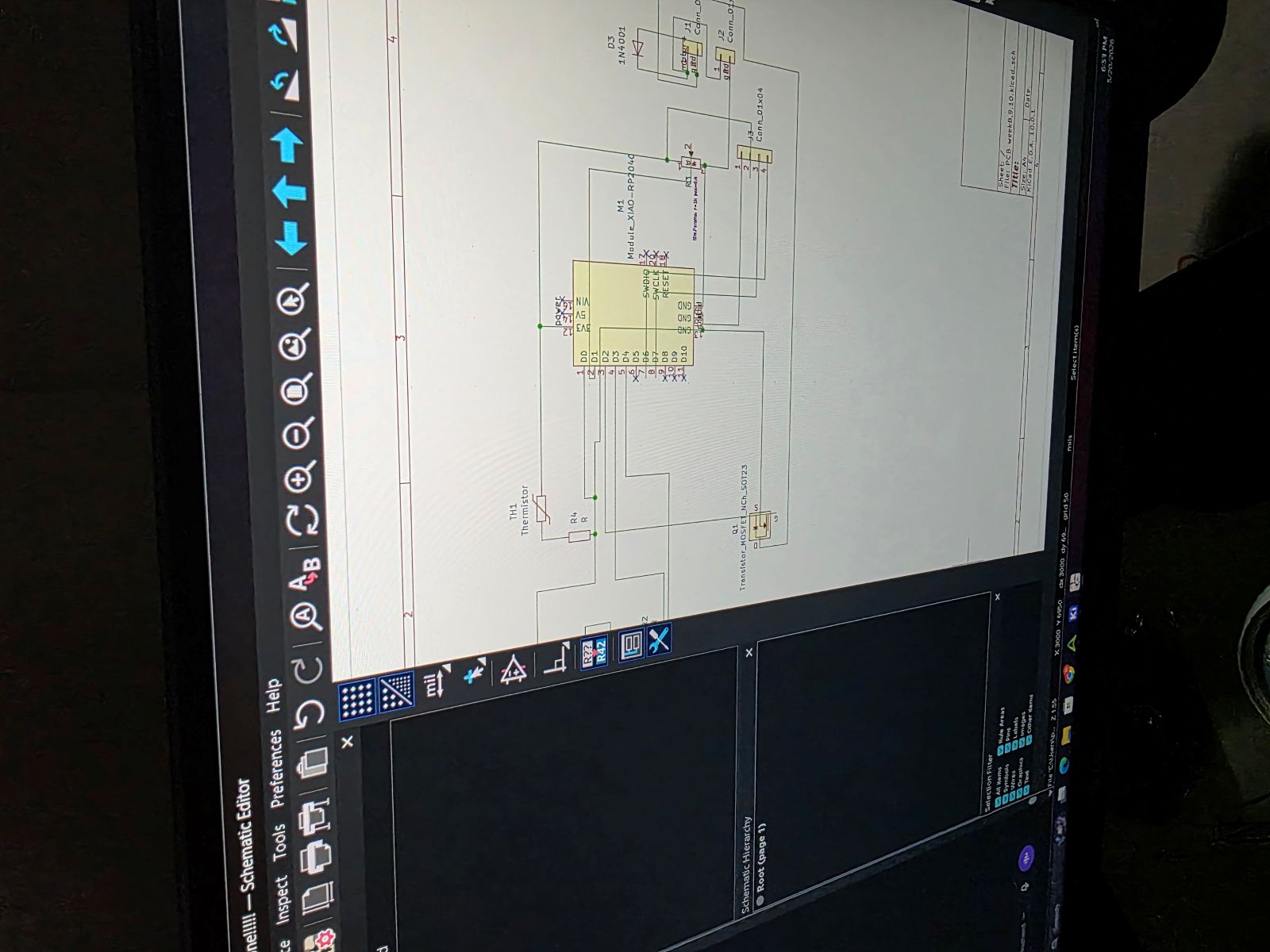
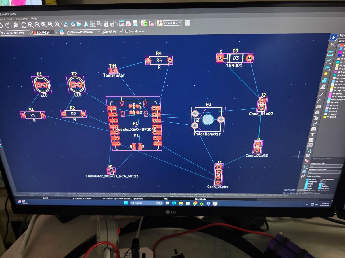
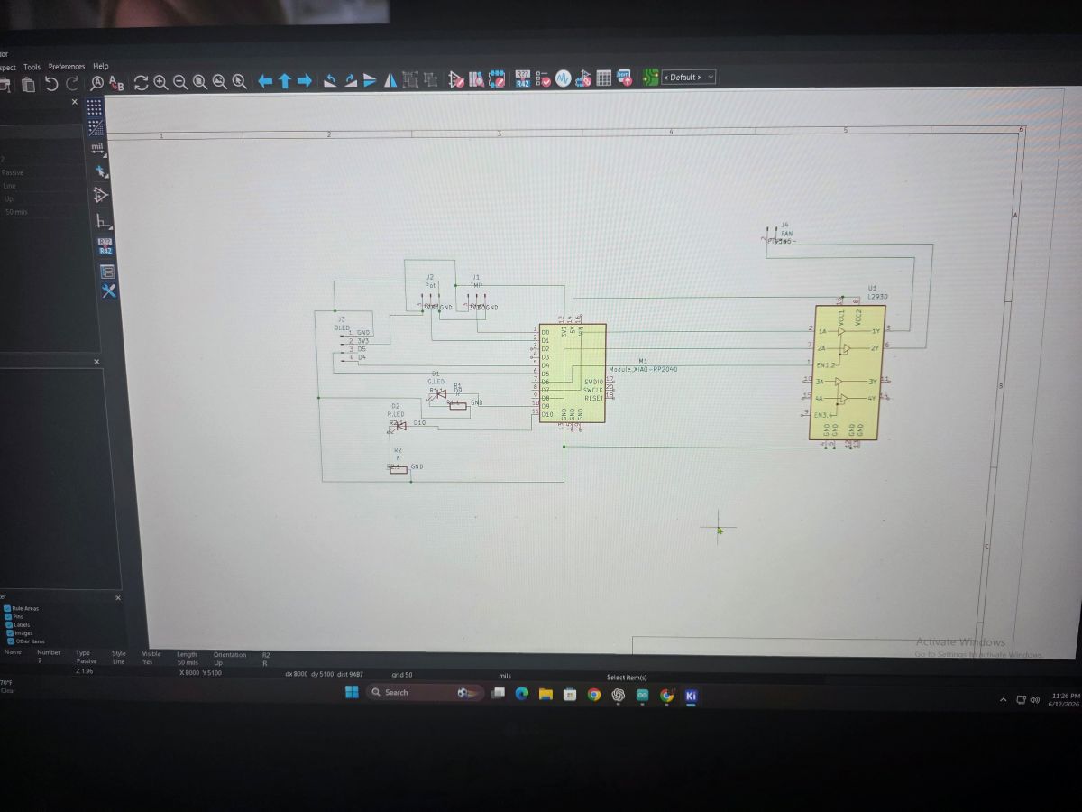
KiCad Design With Input Connections
I designed the board in KiCad with spots for the TMP36 sensor and potentiometer input. The TMP36 was connected to analog pin A0, and the potentiometer was connected to analog pin A1. These were the two inputs that the RP2350 was reading.
I had to make sure the sensor and knob had power, ground, and a signal line back to the microcontroller. That is the big thing with analog inputs: the microcontroller needs a clean signal to read or the numbers will jump around.
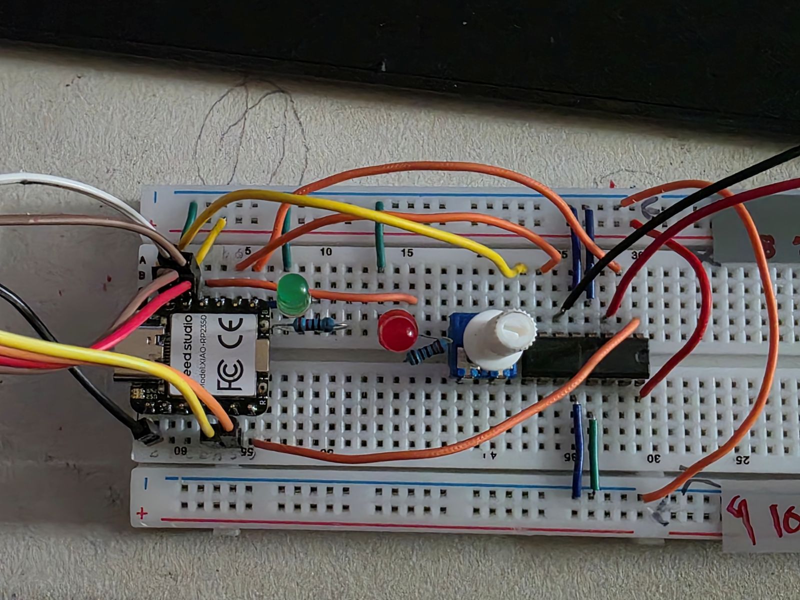
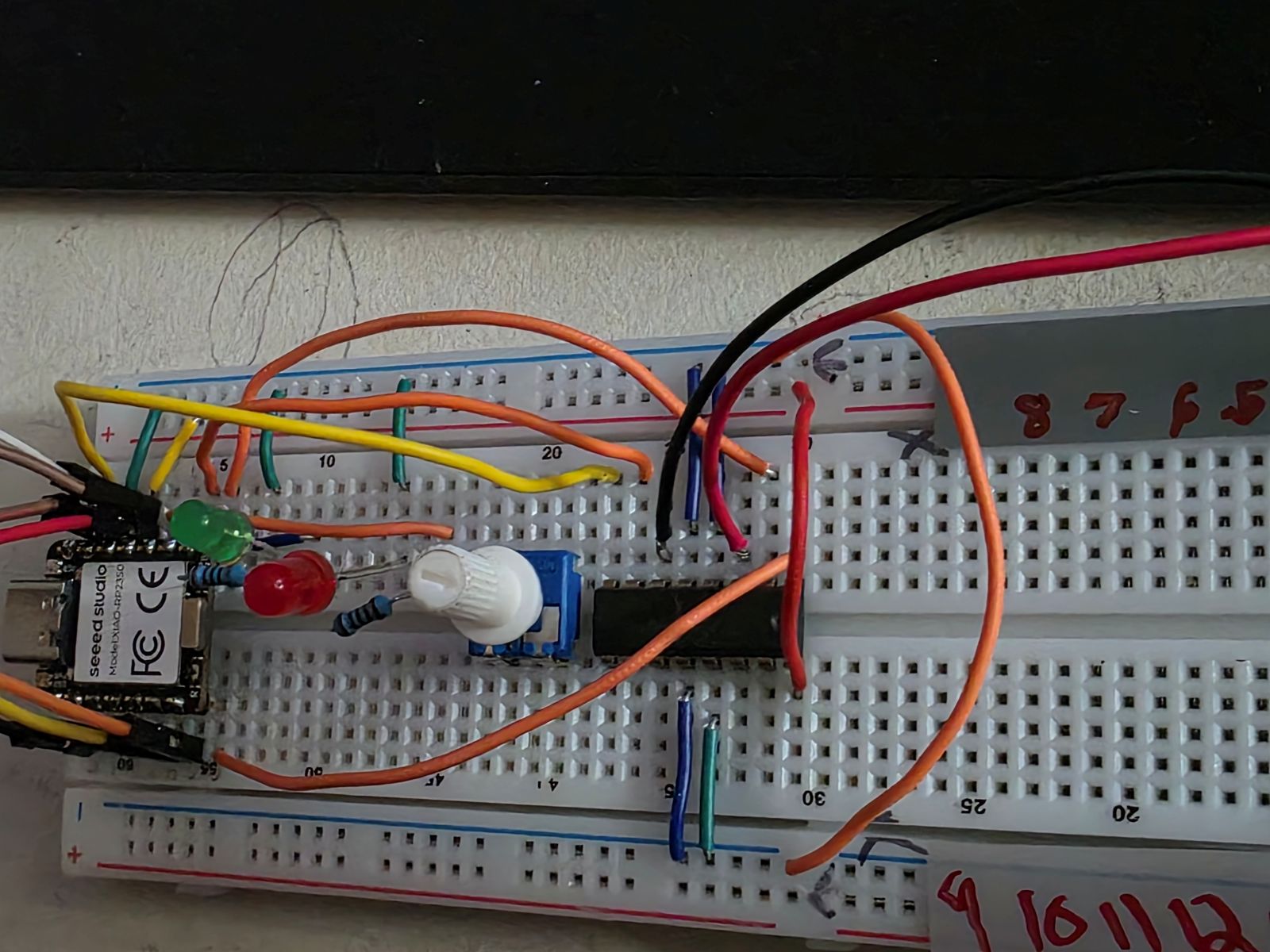
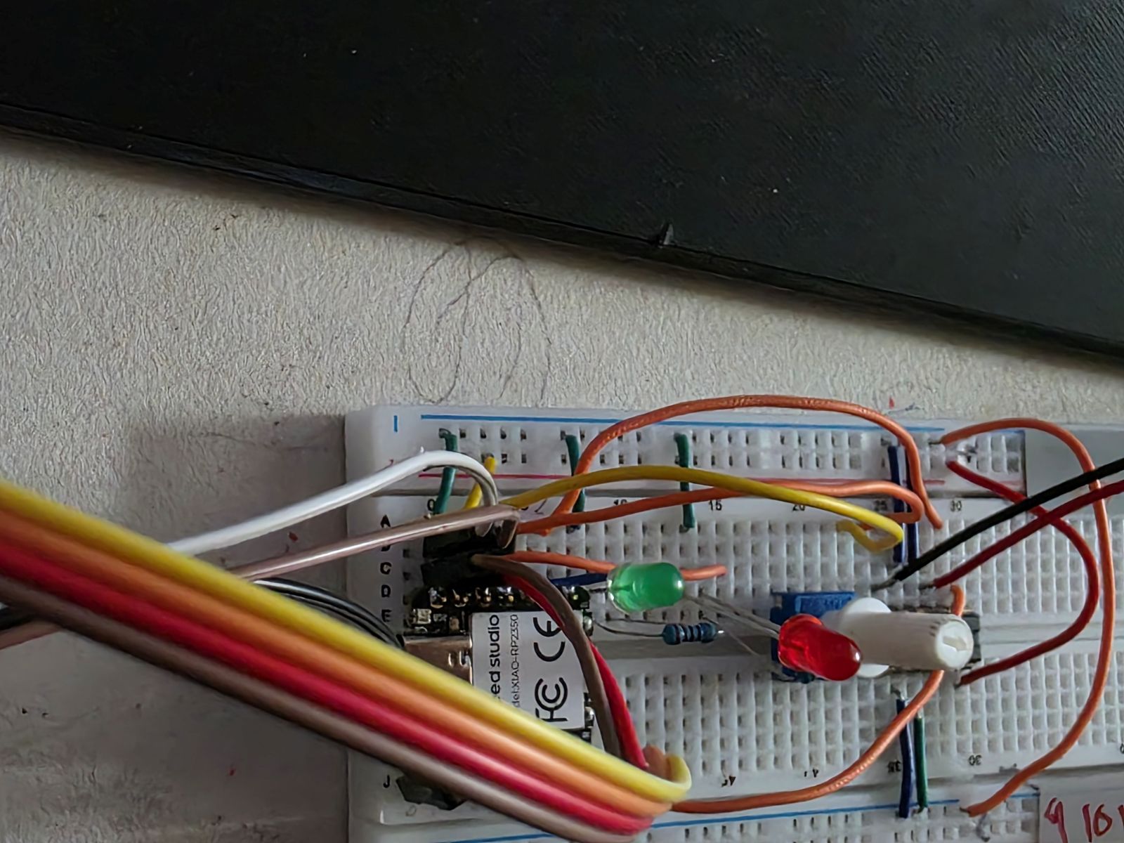
Breadboard Input Testing
Before trusting the PCB, I tested the input devices on a breadboard. This was where I made sure the TMP36 was reading temperature and the potentiometer was changing values when I turned it.
This part was important because if the sensor or knob did not work on the breadboard, then the PCB would not magically fix it. Breadboard testing let me check the wiring, code, sensor direction, and pin numbers before soldering everything permanently.
How the Inputs Controlled the System
The TMP36 measured the temperature. When I touched or warmed up the sensor, the temperature reading went up. Once it reached the hot limit, the system changed states. The green LED turned off, the red LED turned on, and the motor started running.
The potentiometer controlled the motor speed. The RP2350 read the knob value and mapped it from an analog reading into a PWM motor value. So when the system was hot, turning the knob changed how fast the motor spun.
The OLED made this easier to understand because it showed the temperature, the hot limit, and whether the motor was OFF or running at a percentage.
Watch my Week 8, 9, and 10 working demo video
Input Device Code
This is the code I used in Arduino IDE. For Week 9, the important parts are where the code reads the TMP36 on
A0 and the potentiometer on A1.
#include <Wire.h>
#include <Adafruit_GFX.h>
#include <Adafruit_SSD1306.h>
// OLED on Seeed XIAO RP2350
#define OLED_ADDR 0x3C
// TMP36
#define TMP36_PIN A0 // D0
// Potentiometer
#define POT_PIN A1 // D1
// LEDs
#define GREEN_LED D9
#define RED_LED D10
// L293DNE motor driver
#define MOTOR_EN D6
#define MOTOR_IN1 D7
#define MOTOR_IN2 D8
// Red LED and motor turn on at this temp
#define HOT_TEMP_F 83.0
Adafruit_SSD1306 display(128, 64, &Wire1, -1);
float readTempF() {
long total = 0;
for (int i = 0; i < 100; i++) {
total += analogRead(TMP36_PIN);
delay(2);
}
float raw = total / 100.0;
float voltage = raw * (3.3 / 1023.0);
float tempC = (voltage - 0.5) * 100.0;
float tempF = (tempC * 1.8) + 32.0;
return tempF;
}
void motorOff() {
analogWrite(MOTOR_EN, 0);
digitalWrite(MOTOR_IN1, LOW);
digitalWrite(MOTOR_IN2, LOW);
}
void motorOn(int speedPWM) {
digitalWrite(MOTOR_IN1, HIGH);
digitalWrite(MOTOR_IN2, LOW);
analogWrite(MOTOR_EN, speedPWM);
}
void setup() {
Serial.begin(115200);
delay(500);
analogReadResolution(10);
pinMode(GREEN_LED, OUTPUT);
pinMode(RED_LED, OUTPUT);
pinMode(MOTOR_EN, OUTPUT);
pinMode(MOTOR_IN1, OUTPUT);
pinMode(MOTOR_IN2, OUTPUT);
motorOff();
Wire1.begin();
if (!display.begin(SSD1306_SWITCHCAPVCC, OLED_ADDR)) {
Serial.println("OLED not found");
while (true) {
delay(500);
}
}
display.clearDisplay();
display.setTextColor(SSD1306_WHITE);
display.setTextSize(1);
display.setCursor(0, 0);
display.println("System ready");
display.display();
delay(1000);
}
void loop() {
float tempF = readTempF();
int potRaw = analogRead(POT_PIN);
int speedPWM = map(potRaw, 0, 1023, 0, 255);
int speedPercent = map(speedPWM, 0, 255, 0, 100);
bool hot = tempF >= HOT_TEMP_F;
if (hot) {
digitalWrite(RED_LED, HIGH);
digitalWrite(GREEN_LED, LOW);
motorOn(speedPWM);
} else {
digitalWrite(RED_LED, LOW);
digitalWrite(GREEN_LED, HIGH);
motorOff();
}
display.clearDisplay();
display.setTextSize(1);
display.setCursor(0, 0);
display.println("RP2350 TEMP MOTOR");
display.setTextSize(2);
display.setCursor(0, 14);
display.print(tempF, 1);
display.println("F");
display.setTextSize(1);
display.setCursor(0, 38);
display.print("Limit: ");
display.print(HOT_TEMP_F, 0);
display.print("F ");
if (hot) {
display.println("HOT");
} else {
display.println("OK");
}
display.setCursor(0, 52);
display.print("Motor: ");
if (hot) {
display.print(speedPercent);
display.println("%");
} else {
display.println("OFF");
}
display.display();
Serial.print("Temp F: ");
Serial.print(tempF, 1);
Serial.print(" Pot: ");
Serial.print(potRaw);
Serial.print(" PWM: ");
Serial.print(speedPWM);
Serial.print(" Motor: ");
Serial.println(hot ? "ON" : "OFF");
delay(500);
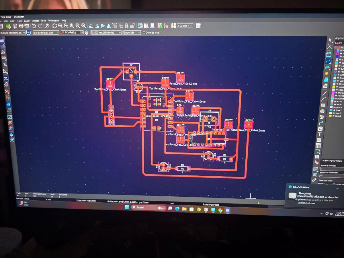
}Making the Input Board
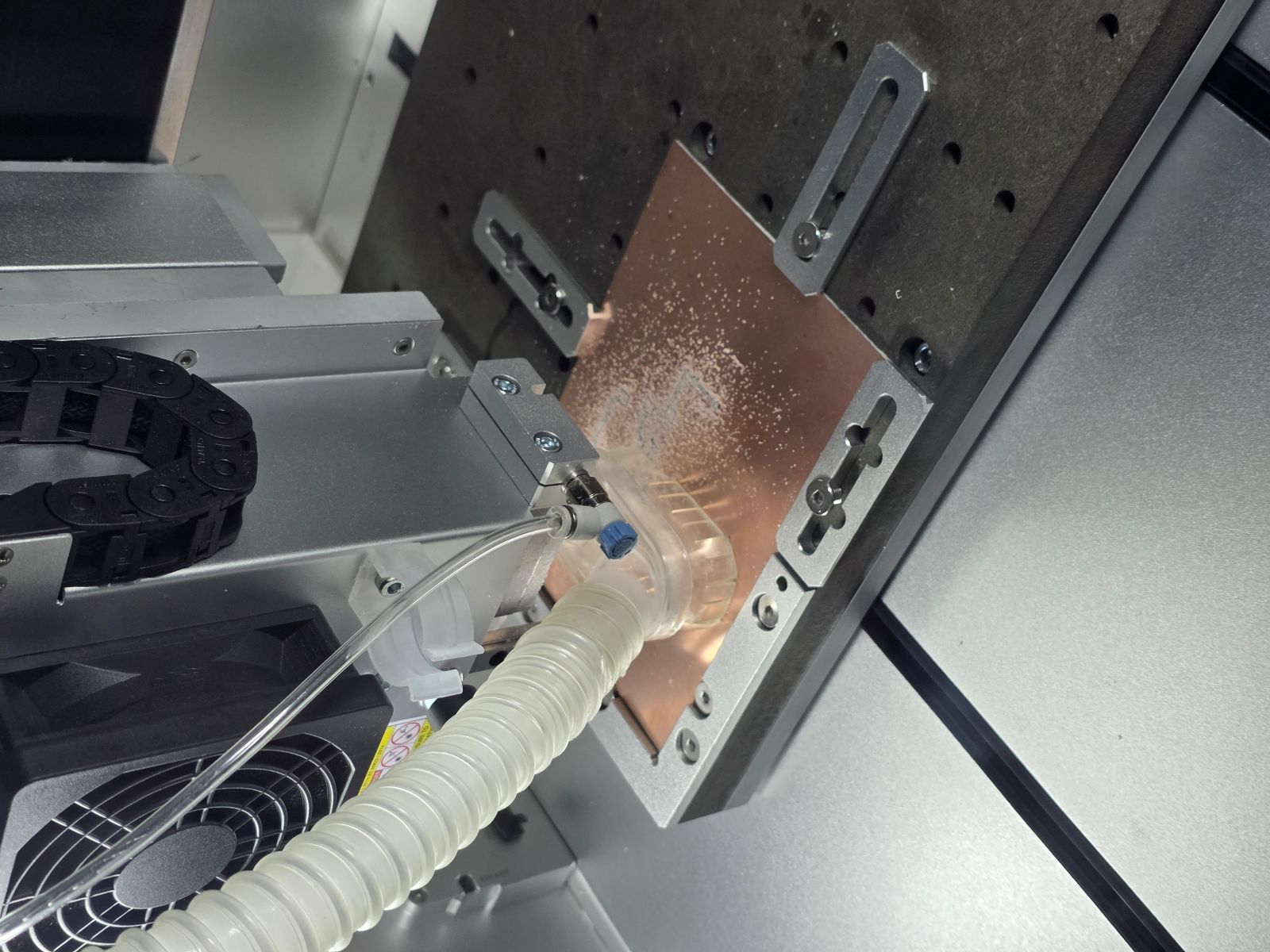
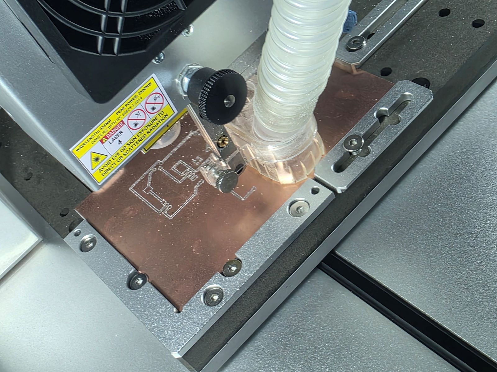
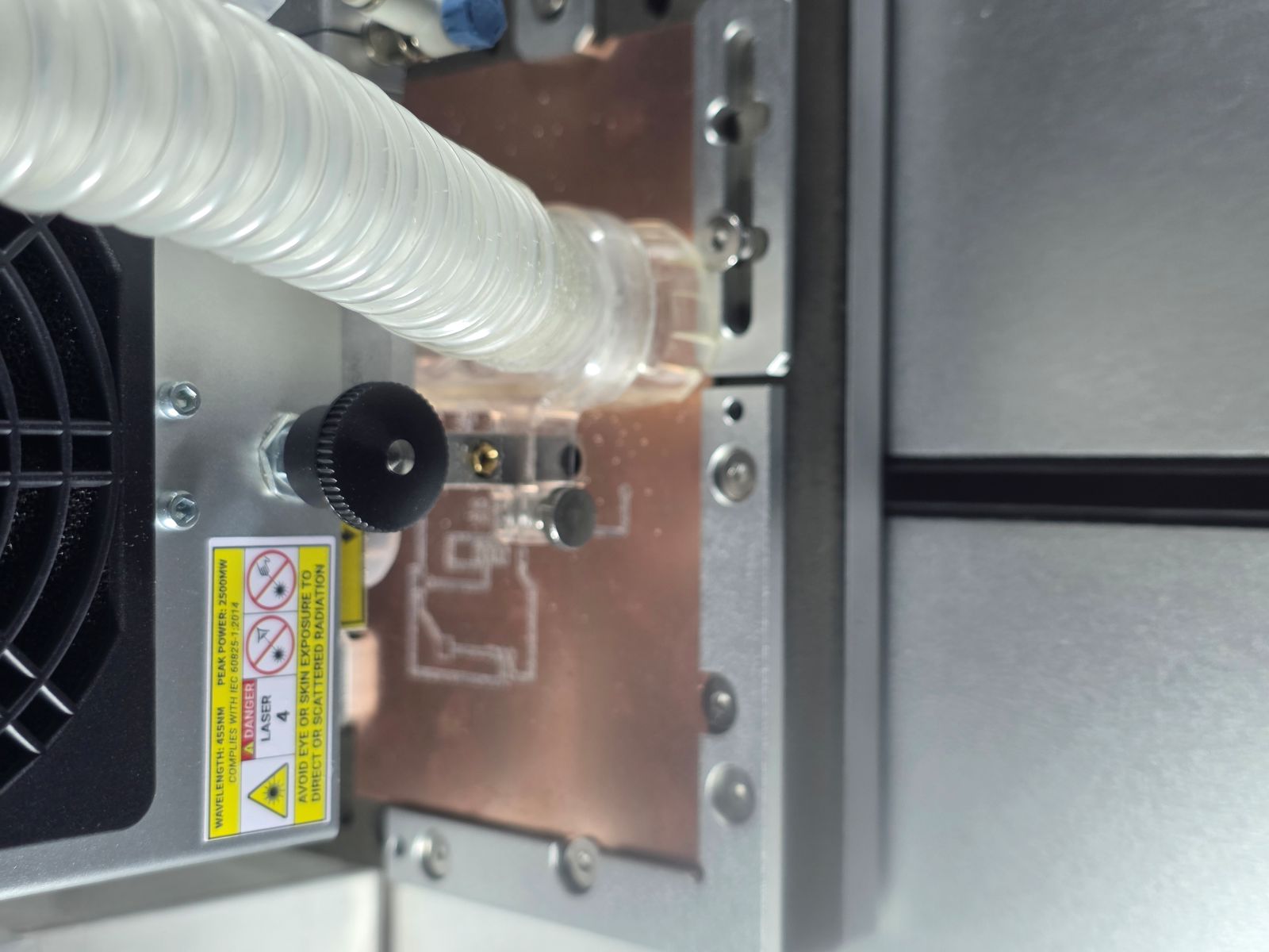
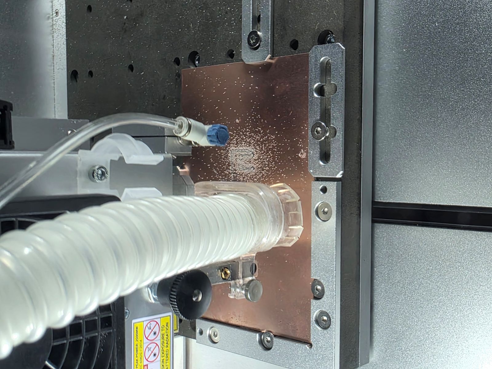
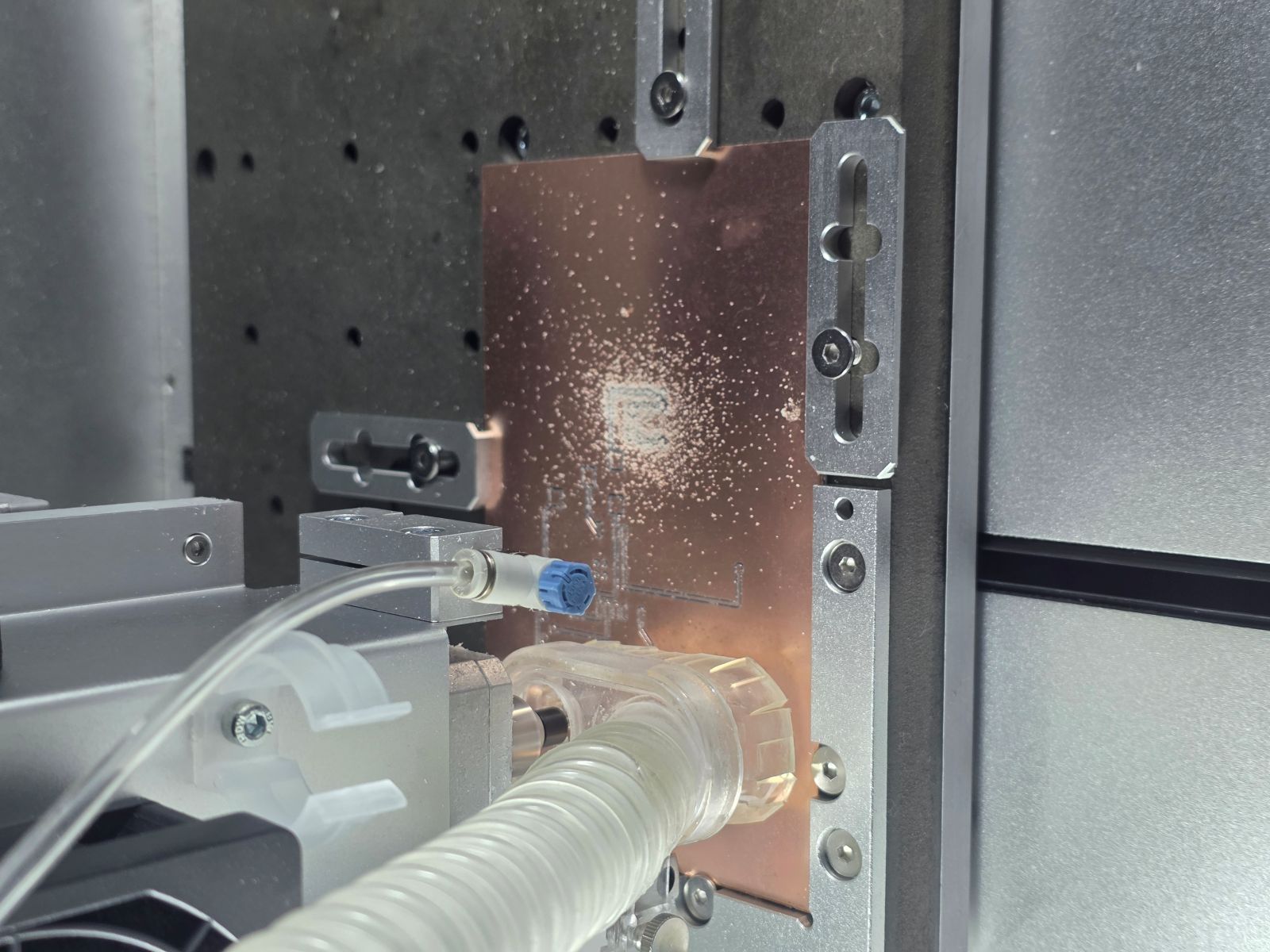
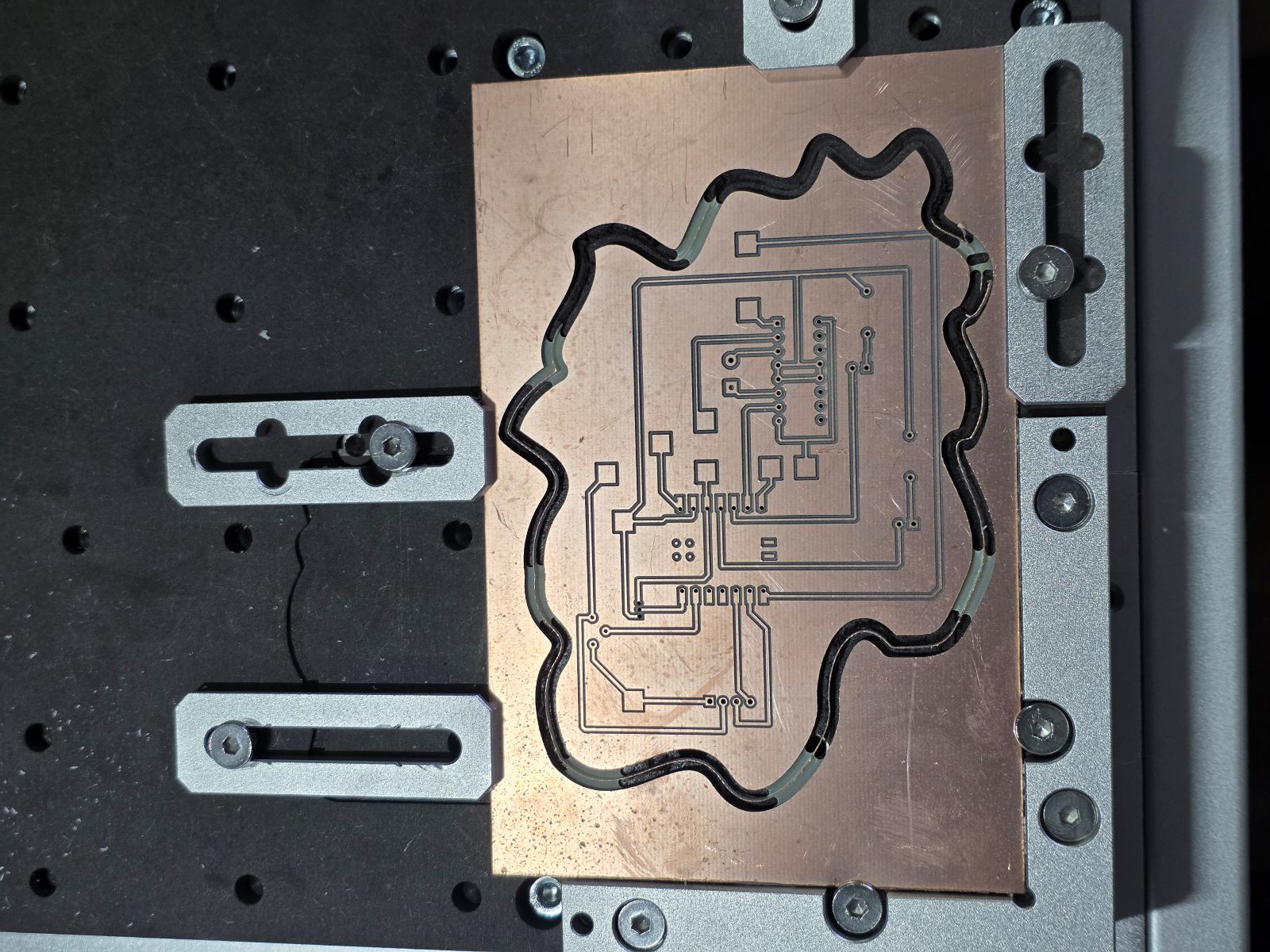
After the input circuit worked on the breadboard, I moved the design into the PCB workflow. These pictures show the board layout and the CAM/toolpath setup in the Makera Carvera software.
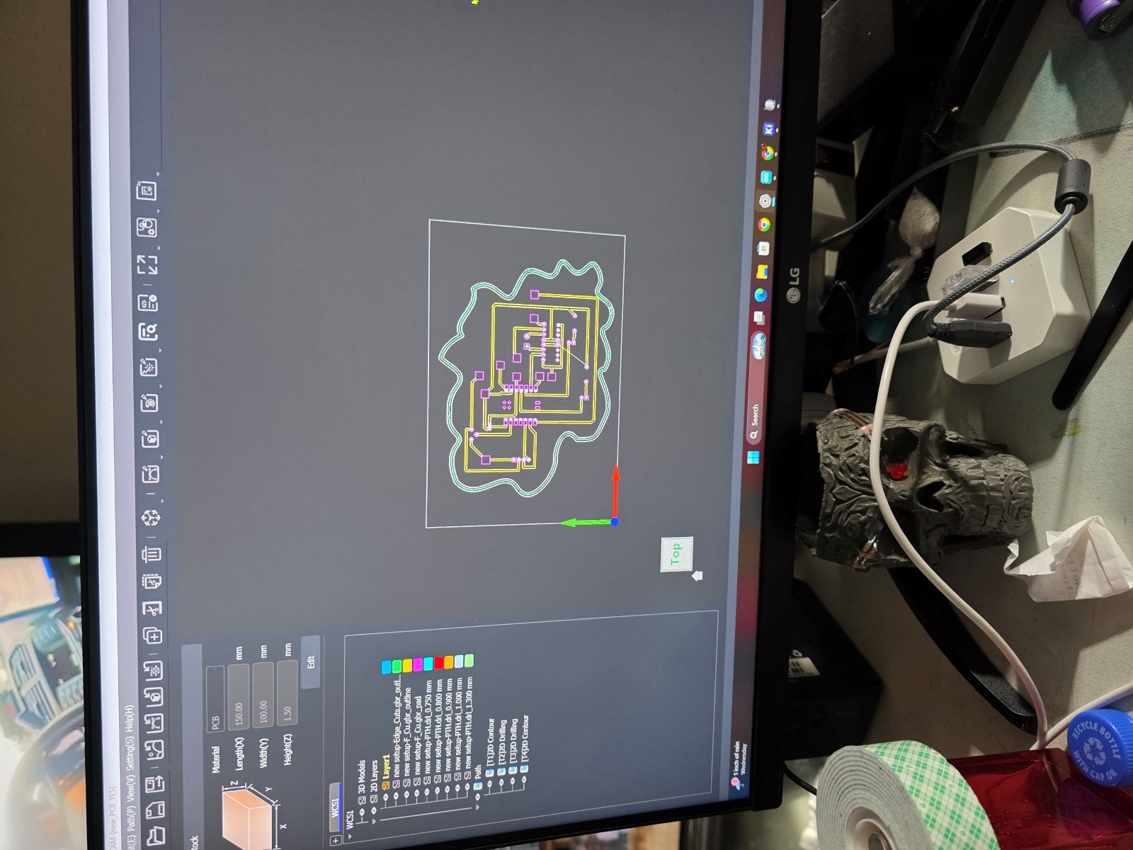
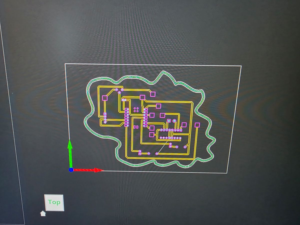
Then I milled the PCB. Even though this is the same physical board used across Weeks 8, 9, and 10, for this week I am focusing on the input side: the TMP36 temperature input and the potentiometer analog input.
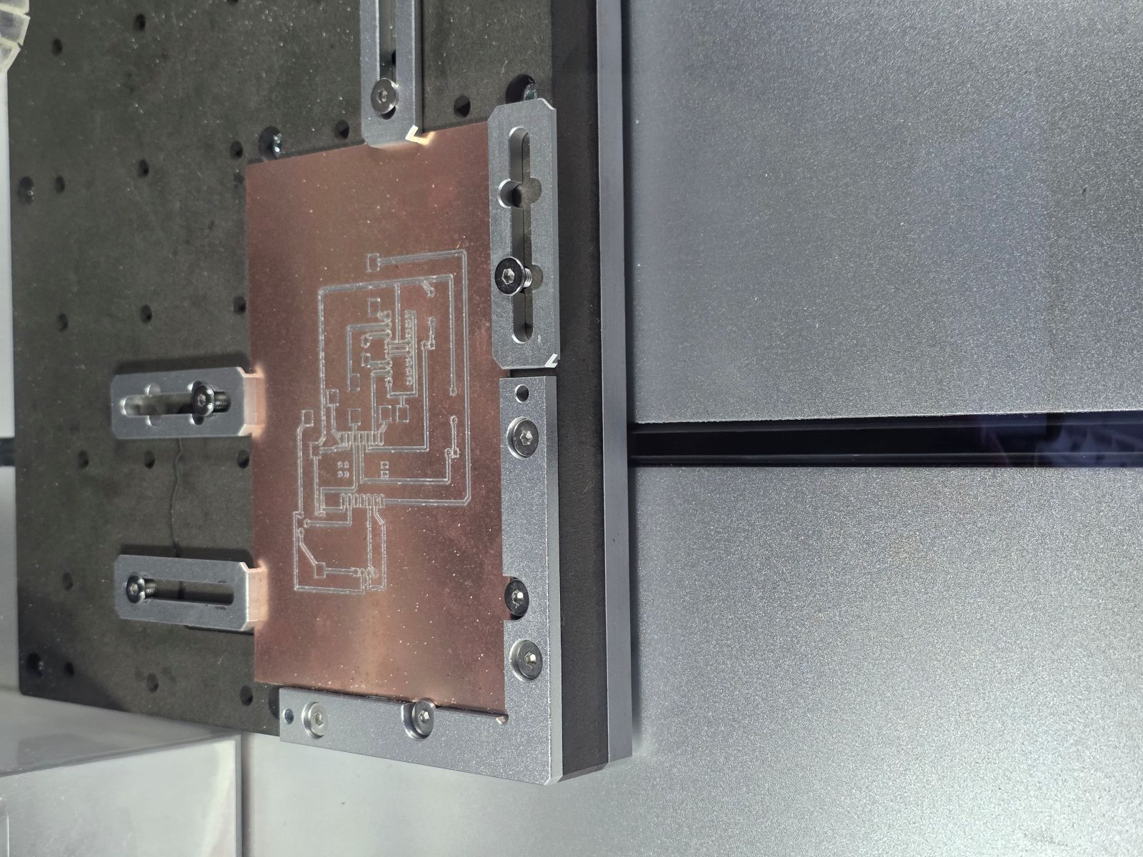
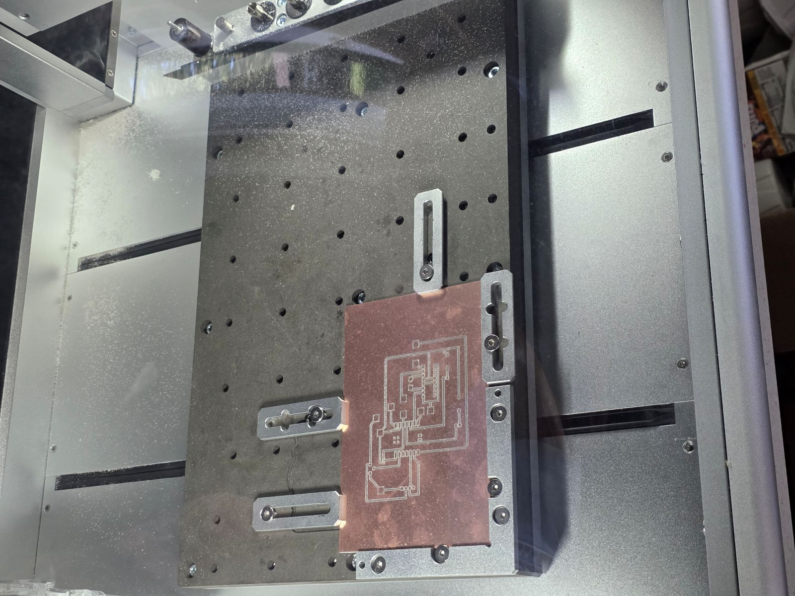


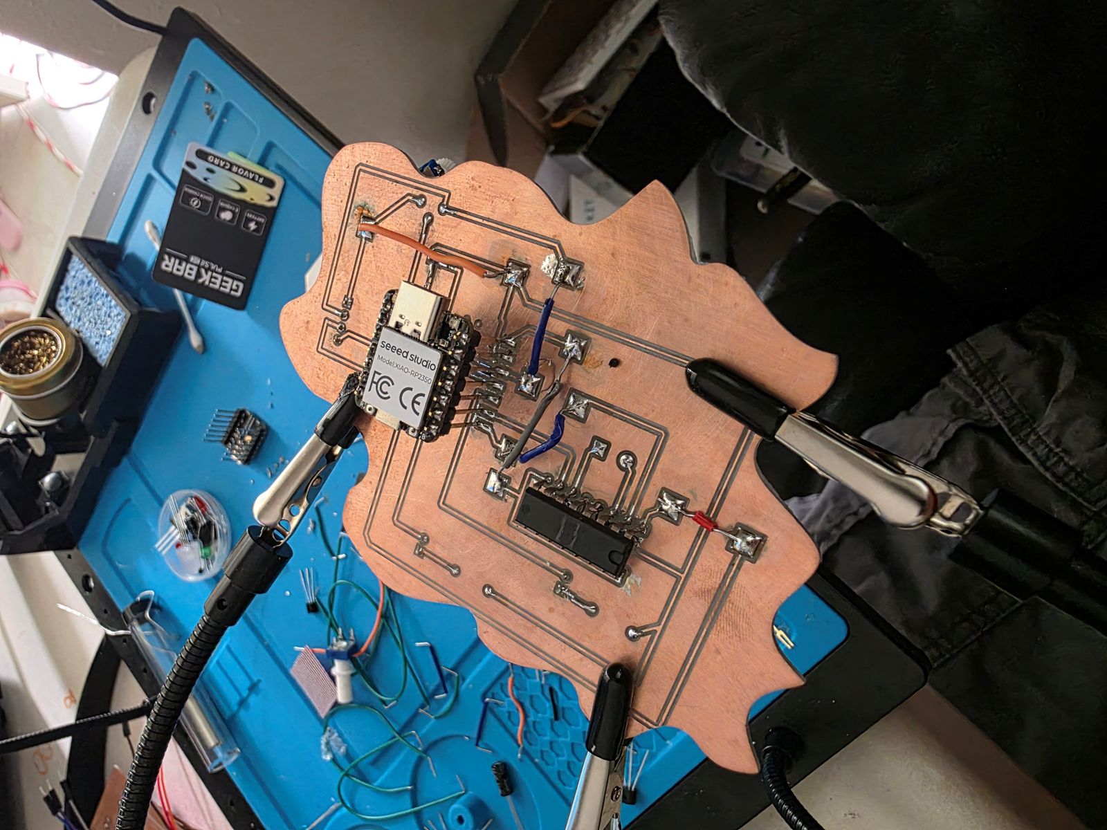
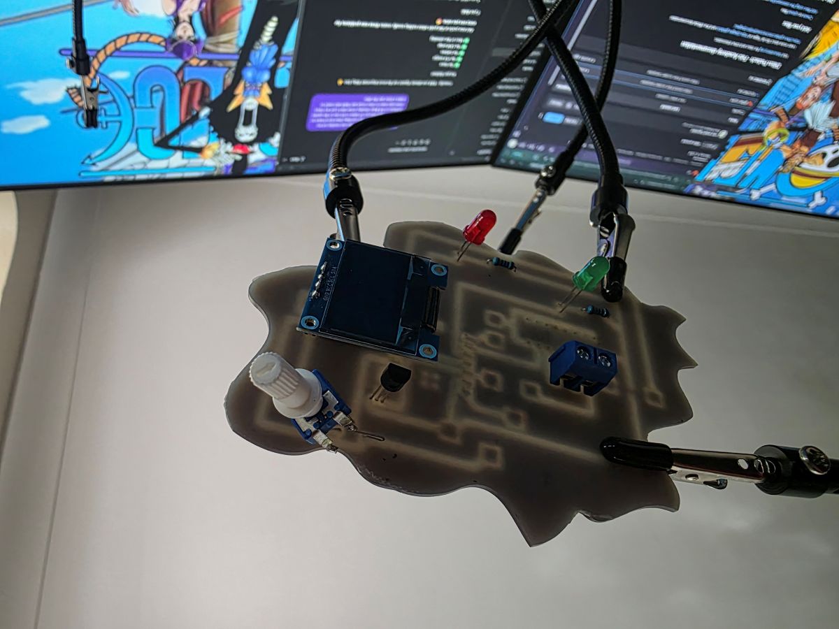
Finished Input Device Board
After the board was milled and soldered, I tested the input devices again. The TMP36 was able to measure temperature, and the potentiometer was able to change the motor speed value. The OLED displayed the sensor reading and motor status, which made it easy to see that the inputs were working.
What I Learned
This week helped me understand input devices way better. I learned that sensors and knobs send information to the microcontroller as voltage signals, and the code turns those signals into numbers I can actually use.
I also learned that analog readings can move around a little, so averaging the TMP36 readings helped make the temperature more stable. The potentiometer was easier to understand because I could turn the knob and immediately see the value change in the motor speed.
The biggest thing I learned is that inputs are what make the board react to the real world. Without the TMP36 and potentiometer, the board would just be running outputs. Once I added inputs, the board could actually measure something and respond to it.
Project Files and Documentation
To support this assignment, I created a shared repository containing my design files, source code, PCB layouts, manufacturing files, and supporting documentation used throughout this project.