Week 8 - Electronics Production
This week was about designing, milling, stuffing, and testing my own PCB.
Assignments
Group Assignment
- Characterize the design rules for our in-house PCB production process.
- Submit a PCB design to a board house.
Individual Assignment
- Make and test an embedded microcontroller system that I designed.
- Extra credit: make it with another process.
Group Assignment - PCB Design Rules
For the group assignment, we had to figure out what our in-house PCB production process could actually handle. This means testing the design rules for milling PCBs in our lab instead of just guessing numbers in KiCad. The big things we cared about were trace width, trace spacing, drilling, tool size, and how clean the CNC could isolate the copper.
This matters because if the traces are too close together, the bit will not clear the copper correctly and the board can short. If the traces are too thin, they can rip up, break, or disappear during milling. So the design rules are basically the safe limits for making boards in our lab.
For our process, we used the Makera Carvera CNC to mill copper-clad PCB material. We looked at how the V-bit removed copper, how clean the isolation cuts were, and how the board needed to be taped down flat. I learned really fast that even if the PCB design looks perfect on the computer, the real board can still fail if the copper board is not flat or the toolpath is not set up right.
Some of the important design-rule things we checked were:
- Minimum trace width that still mills cleanly.
- Minimum spacing between traces and pads.
- How much clearance is needed around small pads.
- How clean the V-bit isolation paths were.
- How accurate the drilled holes were.
- How important it is for the copper board to be flat on the CNC bed.
We also had to submit a PCB design to a board house. The point of that part was to understand the difference between making a PCB in-house and sending the same kind of design out to be professionally manufactured. Board houses usually need Gerber files, drill files, board outline files, and correct design-rule checks before the board can be ordered.
The biggest thing I got from the group work is that PCB production is not just clicking cut. You have to know your machine, your bit, your copper material, your clearance, and your setup. Small numbers matter a lot here.
Individual Assignment - My Embedded Microcontroller Board
For my individual assignment, I made and tested an embedded microcontroller system that I designed. My board used a Seeed XIAO RP2350 as the microcontroller. I connected it to an OLED screen, a TMP36 temperature sensor, a potentiometer, red and green LEDs, and an L293DNE motor driver to control a small DC motor.
The idea of the system was simple: read the temperature, show it on the OLED, and if it gets hot enough, turn on the red LED and run the motor like a little cooling fan. If the temperature is okay, the green LED stays on and the motor stays off. The potentiometer controls the motor speed when the motor turns on.
KiCad PCB Design
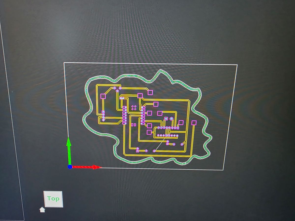
I started by designing the circuit in KiCad. I had to place the Seeed XIAO RP2350, the motor driver, the OLED connections, the TMP36 sensor, the potentiometer, the LEDs, resistors, power, and ground connections.
This part took some time because the board had to be routed in a way that could actually be milled. I could not just make tiny traces and hope for the best. I had to think about trace size, spacing, component placement, and where the milling bit would need to cut.
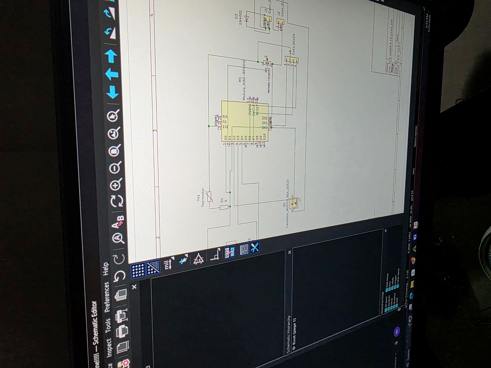
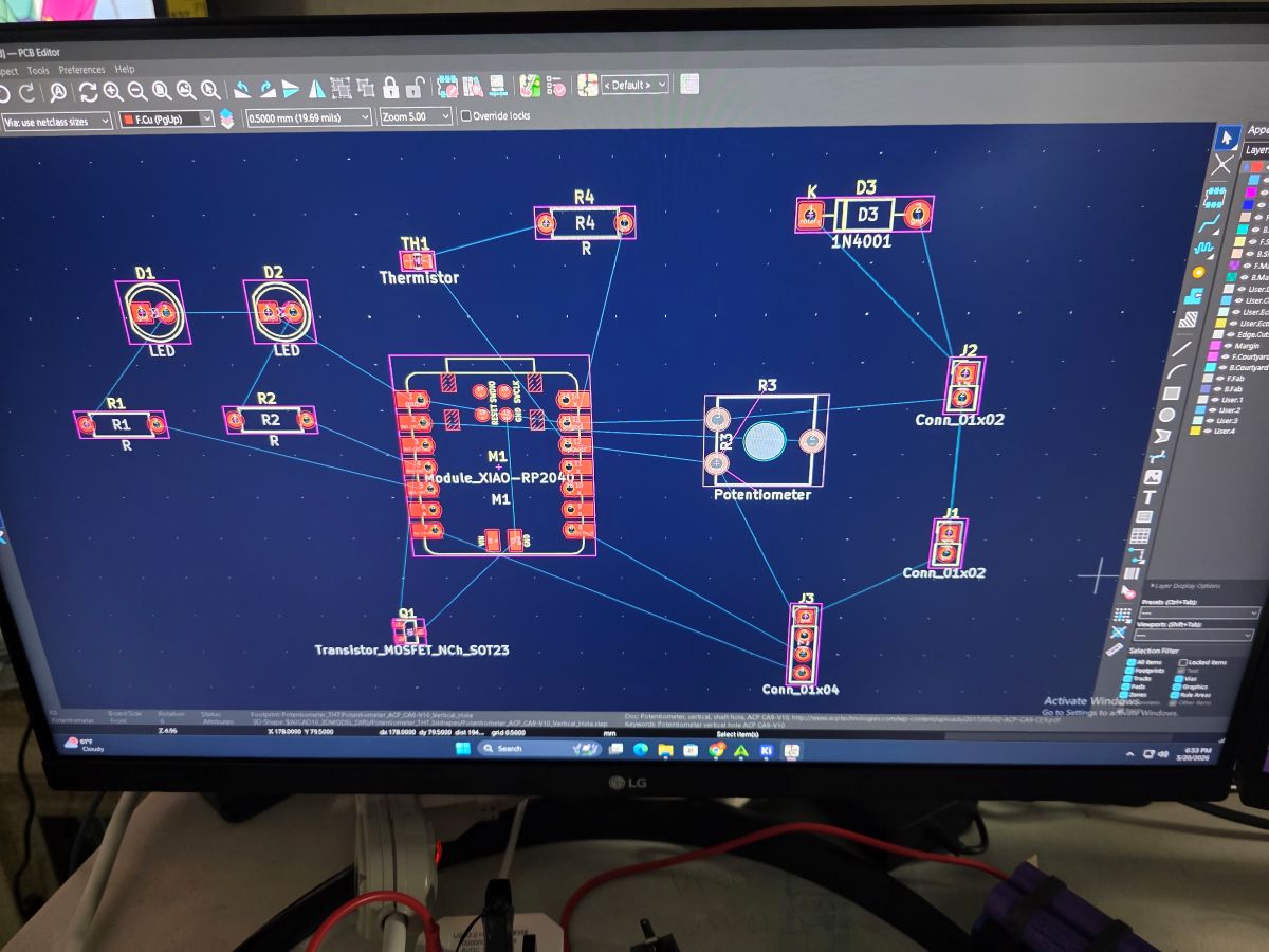
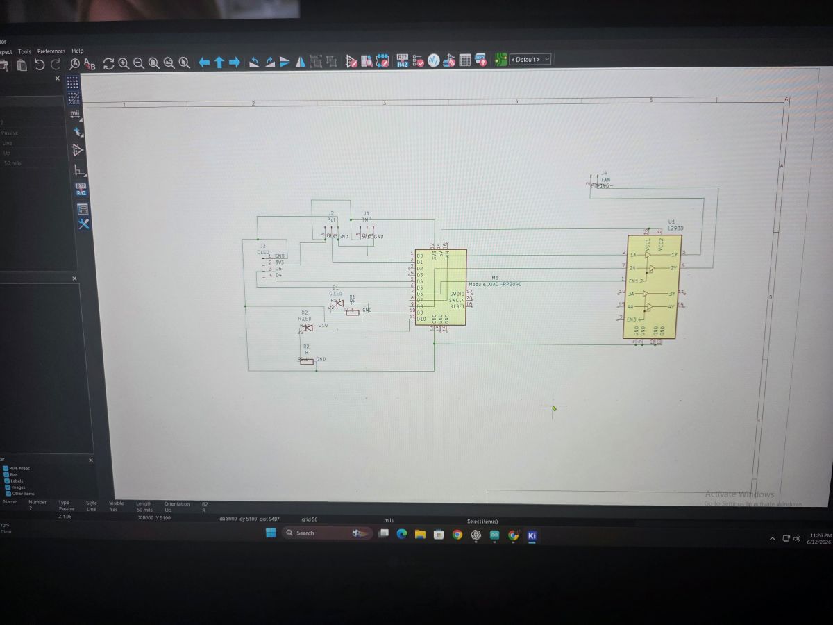
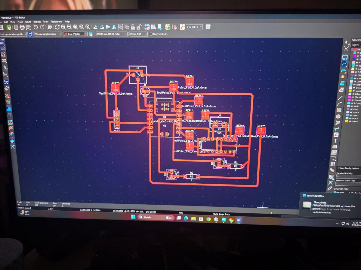
These pictures show the KiCad part of the project. This is where I was working through the schematic and board layout before making the real PCB.
Arduino IDE Code
After getting the board planned out, I worked on the code in the Arduino IDE. The code reads the TMP36 temperature sensor, reads the potentiometer, updates the OLED screen, and controls the red LED, green LED, and motor driver.
One thing that mattered here was the OLED. On the RP2350, I used Wire1 for I2C, so the OLED setup
had to match the pins I was using. I also averaged the temperature reading because analog readings can bounce
around a little bit.
#include <Wire.h>
#include <Adafruit_GFX.h>
#include <Adafruit_SSD1306.h>

// OLED on Seeed XIAO RP2350
#define OLED_ADDR 0x3C

// TMP36
#define TMP36_PIN A0   // D0

// Potentiometer
#define POT_PIN A1     // D1

// LEDs
#define GREEN_LED D9
#define RED_LED D10

// L293DNE motor driver
#define MOTOR_EN D6
#define MOTOR_IN1 D7
#define MOTOR_IN2 D8

// Red LED and motor turn on at this temp
#define HOT_TEMP_F 83.0

Adafruit_SSD1306 display(128, 64, &Wire1, -1);

float readTempF() {
  long total = 0;

  for (int i = 0; i < 100; i++) {
    total += analogRead(TMP36_PIN);
    delay(2);
  }

  float raw = total / 100.0;
  float voltage = raw * (3.3 / 1023.0);
  float tempC = (voltage - 0.5) * 100.0;
  float tempF = (tempC * 1.8) + 32.0;

  return tempF;
}

void motorOff() {
  analogWrite(MOTOR_EN, 0);
  digitalWrite(MOTOR_IN1, LOW);
  digitalWrite(MOTOR_IN2, LOW);
}

void motorOn(int speedPWM) {
  digitalWrite(MOTOR_IN1, HIGH);
  digitalWrite(MOTOR_IN2, LOW);
  analogWrite(MOTOR_EN, speedPWM);
}

void setup() {
  Serial.begin(115200);
  delay(500);

  analogReadResolution(10);

  pinMode(GREEN_LED, OUTPUT);
  pinMode(RED_LED, OUTPUT);

  pinMode(MOTOR_EN, OUTPUT);
  pinMode(MOTOR_IN1, OUTPUT);
  pinMode(MOTOR_IN2, OUTPUT);

  motorOff();

  // RP2350 D4/D5 OLED uses Wire1
  Wire1.begin();

  if (!display.begin(SSD1306_SWITCHCAPVCC, OLED_ADDR)) {
    Serial.println("OLED not found");
    while (true) {
      delay(500);
    }
  }

  display.clearDisplay();
  display.setTextColor(SSD1306_WHITE);
  display.setTextSize(1);
  display.setCursor(0, 0);
  display.println("System ready");
  display.display();

  delay(1000);
}

void loop() {
  float tempF = readTempF();

  int potRaw = analogRead(POT_PIN);
  int speedPWM = map(potRaw, 0, 1023, 0, 255);
  int speedPercent = map(speedPWM, 0, 255, 0, 100);

  bool hot = tempF >= HOT_TEMP_F;

  if (hot) {
    digitalWrite(RED_LED, HIGH);
    digitalWrite(GREEN_LED, LOW);
    motorOn(speedPWM);
  } else {
    digitalWrite(RED_LED, LOW);
    digitalWrite(GREEN_LED, HIGH);
    motorOff();
  }

  display.clearDisplay();

  display.setTextSize(1);
  display.setCursor(0, 0);
  display.println("RP2350 TEMP MOTOR");

  display.setTextSize(2);
  display.setCursor(0, 14);
  display.print(tempF, 1);
  display.println("F");

  display.setTextSize(1);
  display.setCursor(0, 38);
  display.print("Limit: ");
  display.print(HOT_TEMP_F, 0);
  display.print("F ");

  if (hot) {
    display.println("HOT");
  } else {
    display.println("OK");
  }

  display.setCursor(0, 52);
  display.print("Motor: ");

  if (hot) {
    display.print(speedPercent);
    display.println("%");
  } else {
    display.println("OFF");
  }

  display.display();

  Serial.print("Temp F: ");
  Serial.print(tempF, 1);
  Serial.print("  Pot: ");
  Serial.print(potRaw);
  Serial.print("  PWM: ");
  Serial.print(speedPWM);
  Serial.print("  Motor: ");
  Serial.println(hot ? "ON" : "OFF");

  delay(500);
}
Breadboard Testing
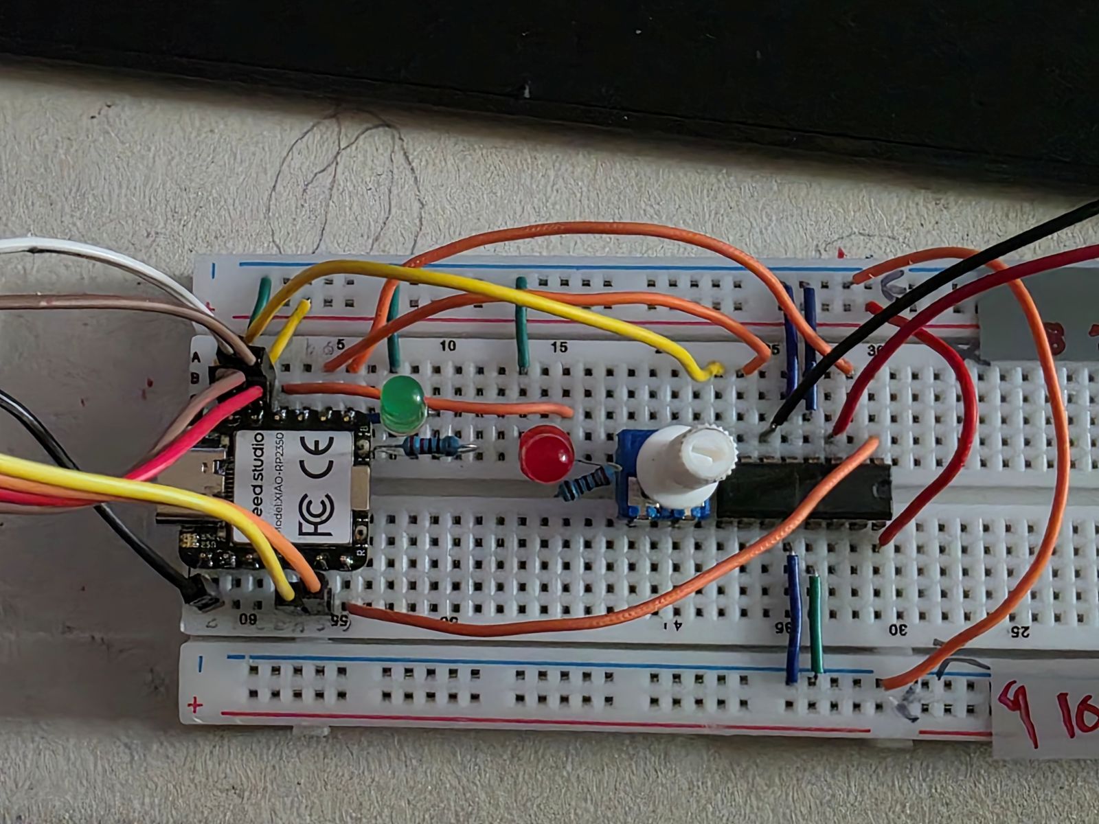
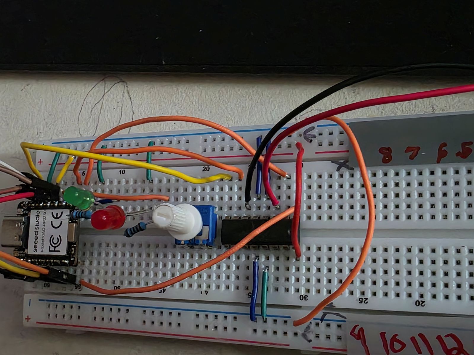
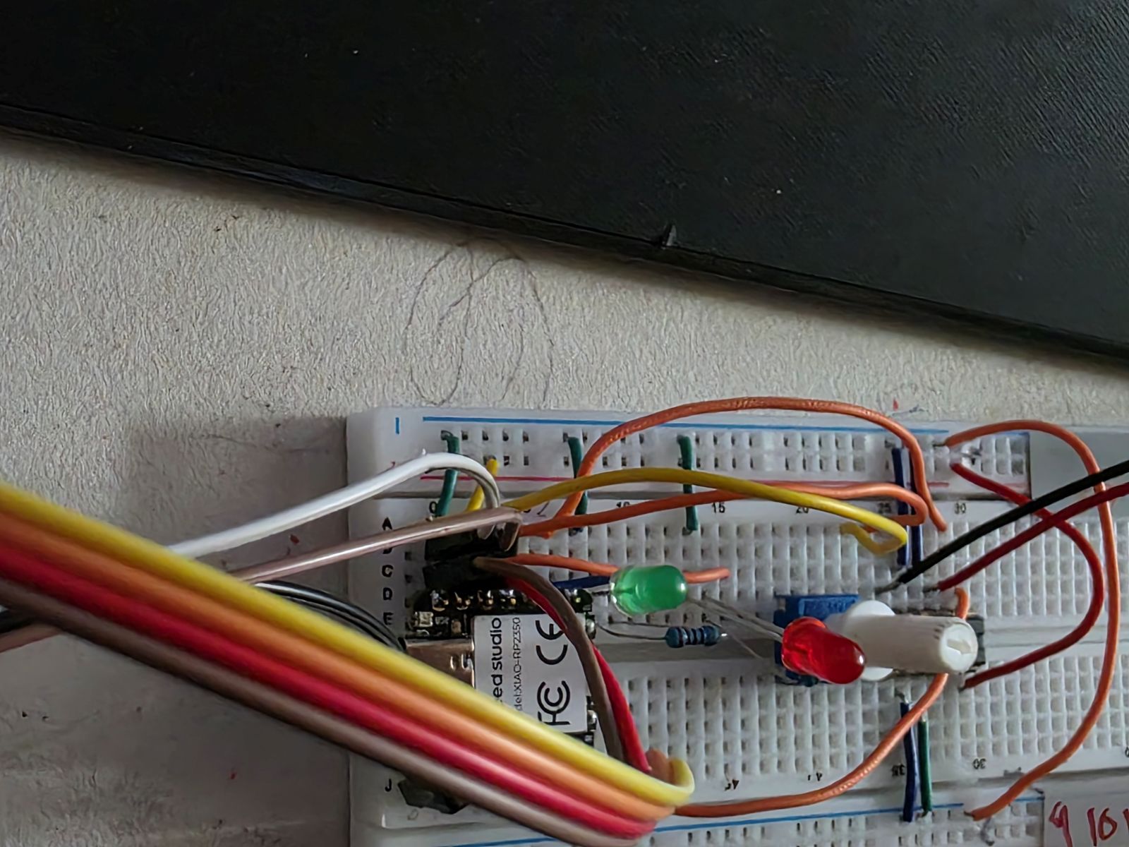
Before trusting the PCB, I built and tested the circuit on a breadboard. This helped me make sure the RP2350, OLED, TMP36, potentiometer, LEDs, motor driver, and motor were all working before I committed everything to the milled board.
This was a big step because if something did not work on the breadboard, it would be even harder to troubleshoot after soldering it to a PCB. Testing it first let me prove the code and wiring before making the final board.
Once I had the breadboard working, I made a video showing Weeks 8, 9, and 10 working together. This video shows the system reading temperature, using the input, and controlling the outputs.
Watch my Week 8, 9, and 10 working demo video
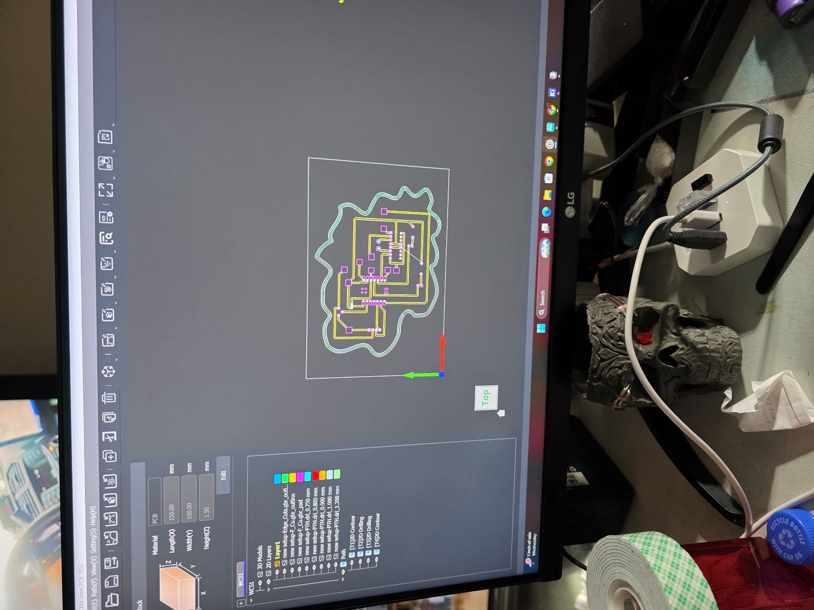
Makera Carvera CAM and Toolpaths
After the design was done in KiCad, I moved into the Makera Carvera software to set up the milling process. I had to bring the PCB files into the CAM software and create the toolpaths for the board.
The toolpaths included the copper isolation cuts, the drilled holes, and the outside board cut. This is where I had to make sure the correct tool was selected and the cut depth was right. If the bit goes too shallow, it does not clear the copper. If it goes too deep, it can tear up the board or make the traces too thin.
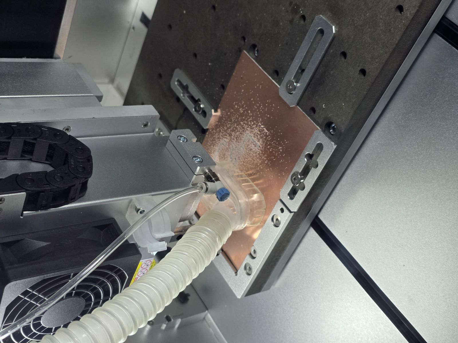
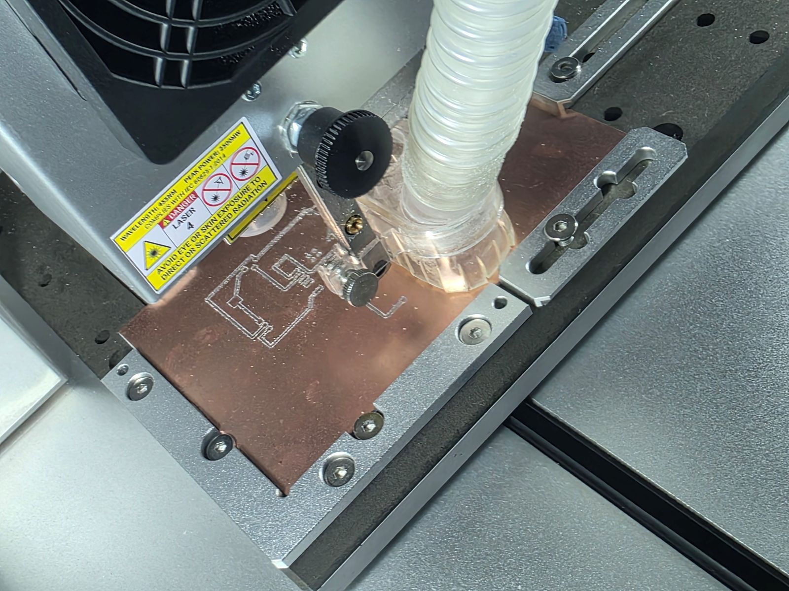
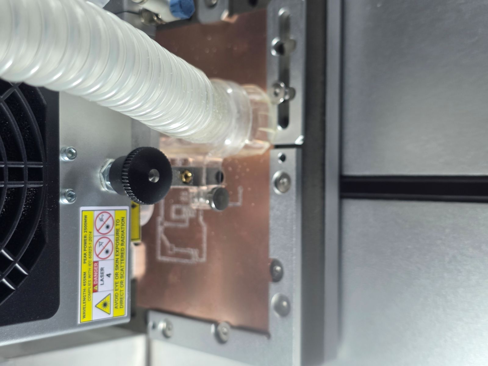
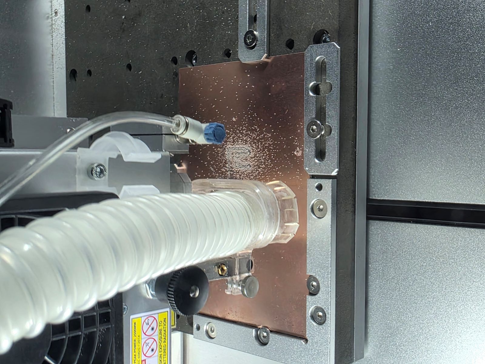
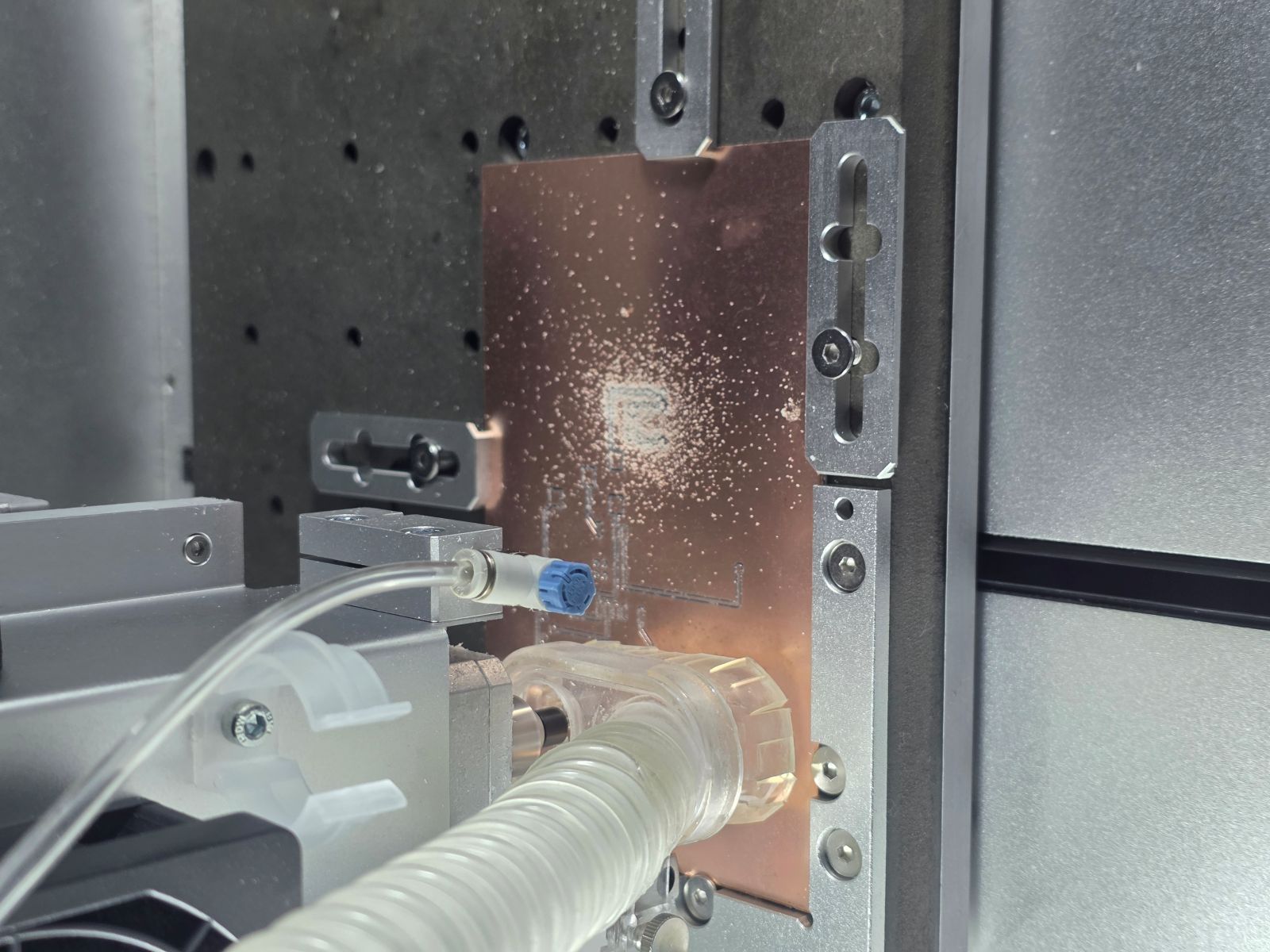
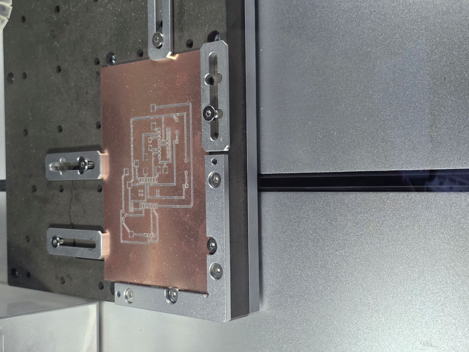
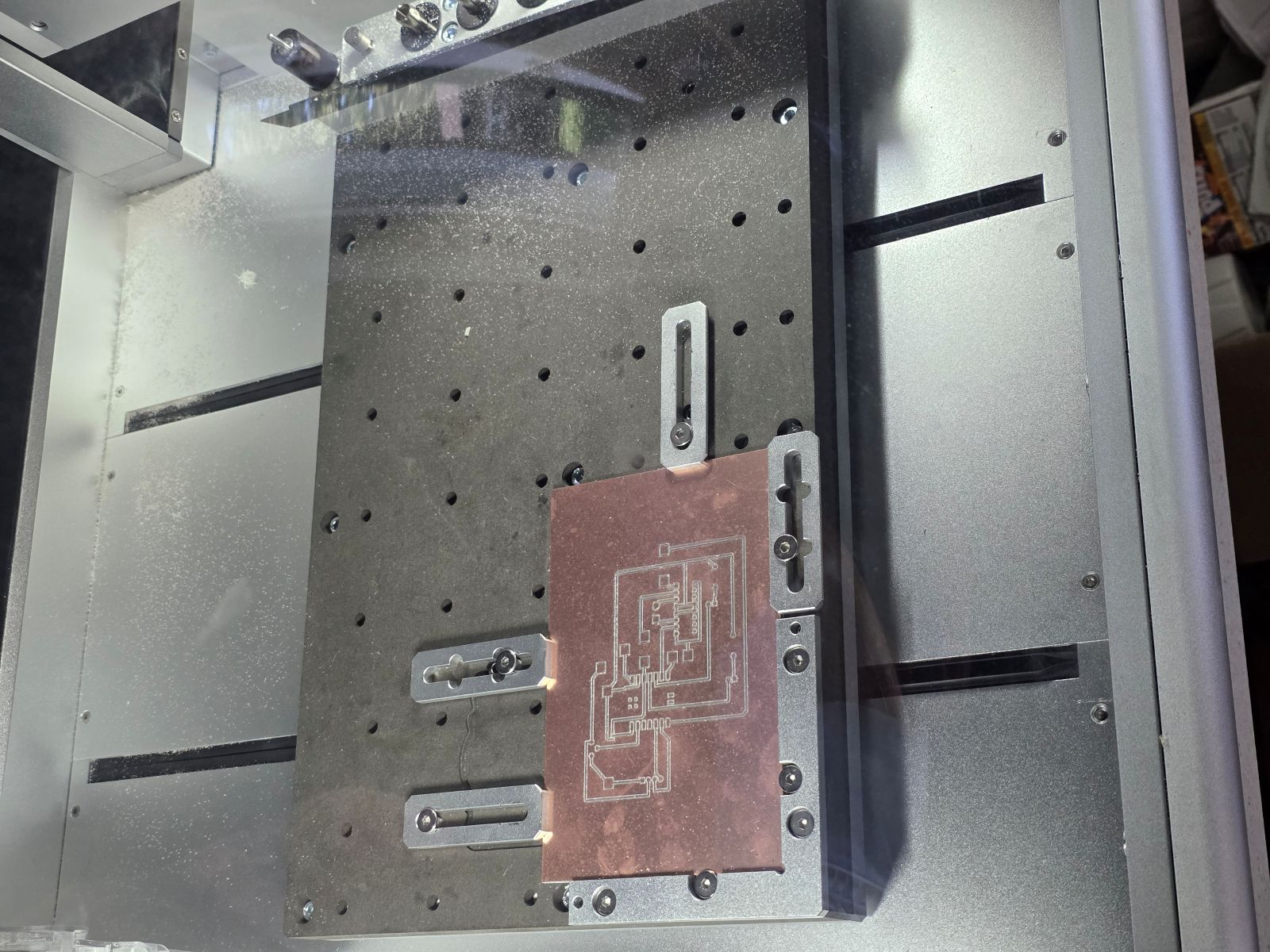
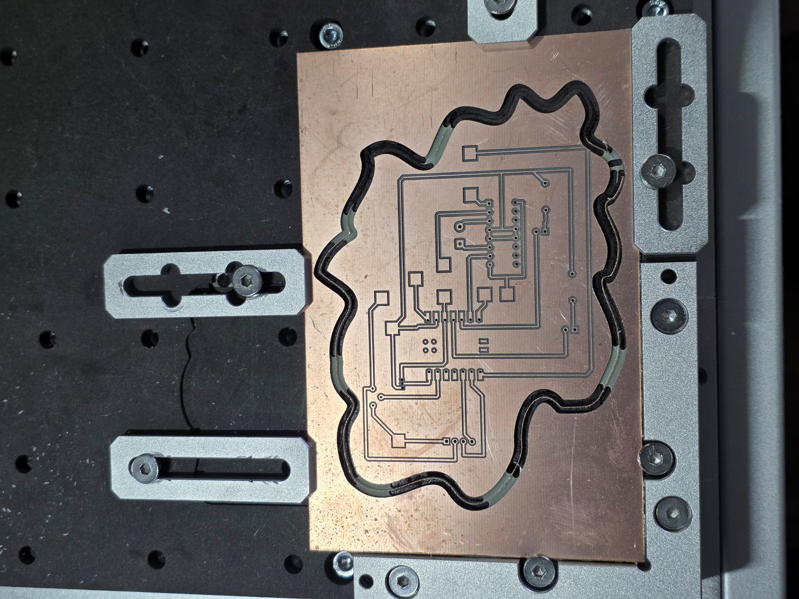
Milling the PCB
Next, I milled the PCB on the Makera Carvera. This part was slow but super important. I had to make sure the board was flat, the bit was set correctly, and the toolpath was cutting the copper cleanly.
While the board was milling, I watched the traces being cut out. This is where the design-rule testing from the group assignment mattered because the spacing and trace width had to be large enough for the machine to actually make the board.


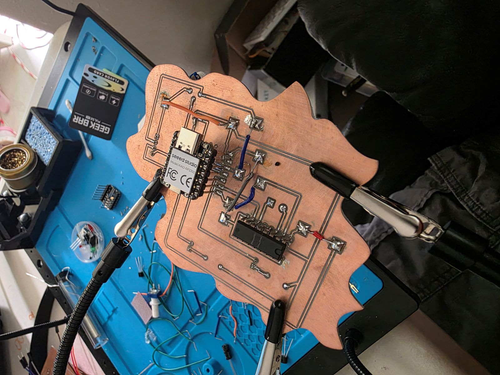
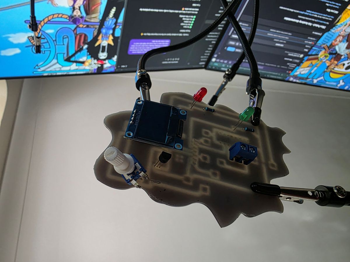
Finished Board and Testing
After milling, I soldered the board and tested it. The finished board worked with the RP2350, the OLED screen, the TMP36 sensor, the potentiometer, the LEDs, and the motor driver. The board could read the sensor, show the temperature, and control the outputs from the code.
When the temperature was under the set limit, the green LED showed the system was okay and the motor stayed off. When the temperature reached the hot limit, the red LED turned on and the motor started running. The potentiometer controlled how fast the motor would run when it was on.
What I Learned
This week taught me that making a PCB is a lot more than just drawing lines in KiCad. I had to design the circuit, think about the actual milling limits, set up CAM toolpaths, mill the board, solder everything, and then test it.
I also learned that testing on a breadboard first saves a lot of headaches. Once I knew the circuit and code worked, it made the PCB troubleshooting way easier because I already knew what the system was supposed to do.
The biggest thing I learned is that PCB production is all about details. Trace width, spacing, board flatness, tool depth, soldering, and code all matter. If one little thing is off, the whole board can fail. But once it works, it feels awesome because it is a real board that I designed, milled, soldered, and tested myself.
Project Files and Documentation
To support this assignment, I created a shared repository containing my design files, source code, PCB layouts, manufacturing files, and supporting documentation used throughout this project.