Week 11 - Networking & Communications
Sending temperature data between two microcontrollers.
Assignments
Group Assignment
- Send a message between two projects.
Individual Assignment
- Design, build, and connect wired or wireless node(s) with network or bus addresses and local input and/or output device(s).
Group Assignment - Sending a Message Between Two Projects
For the group assignment, we had to send a message between two separate projects. For this, we used two different microcontroller setups and made them talk to each other wirelessly with NRF24L01 modules.
One project was the transmitter side. That side used the Seeed RP2350, a TMP36 temperature sensor, an OLED display, and an NRF24L01 wireless module. The RP2350 read the temperature and showed it on the OLED screen. Then it sent a wireless message to the other board.
The second project was the receiver side. That side used the Seeed ESP32-C3, another NRF24L01 module, a red LED, a green LED, and a small fan motor controlled with an IRF540 MOSFET. This board waited for the message from the RP2350 and then reacted to it.
What was happening was pretty simple: when the temperature sensor got warm, the RP2350 sent a message saying the system was hot. The ESP32-C3 received that message and turned on the red LED and fan. When the sensor was cool, the receiver stayed in the green LED state.
To make sure it was actually working, we used the Arduino IDE Serial Monitor to watch messages being sent and received. We also used the LEDs and motor as proof, because if the wireless message worked, the receiver board changed outputs.
This group assignment showed me how two different embedded projects can communicate instead of one board doing everything. One board collected the data, sent the message, and the other board received it and did the action.
Individual Assignment - Wireless Networking System
Assignment Goal
For Week 11, I worked on networking and communication between two different microcontroller boards. Originally, I planned to use the Arduino Uno R3, but I ended up switching things up and using a Seeed RP2350 on one side and a Seeed ESP32-C3 on the other.
The goal was to have one board read the temperature and send information wirelessly to another board. The second board would then react by turning on LEDs and controlling a fan.
Transmitter Side
On the RP2350 side, I connected a temperature sensor to read temperature and an OLED screen to display the data. This side was responsible for detecting when the temperature increased and then sending a signal using NRF24L01 wireless modules.
This made the RP2350 side the input and transmitter side of the system. It collected the sensor data and sent the result to the other board.
Receiver Side
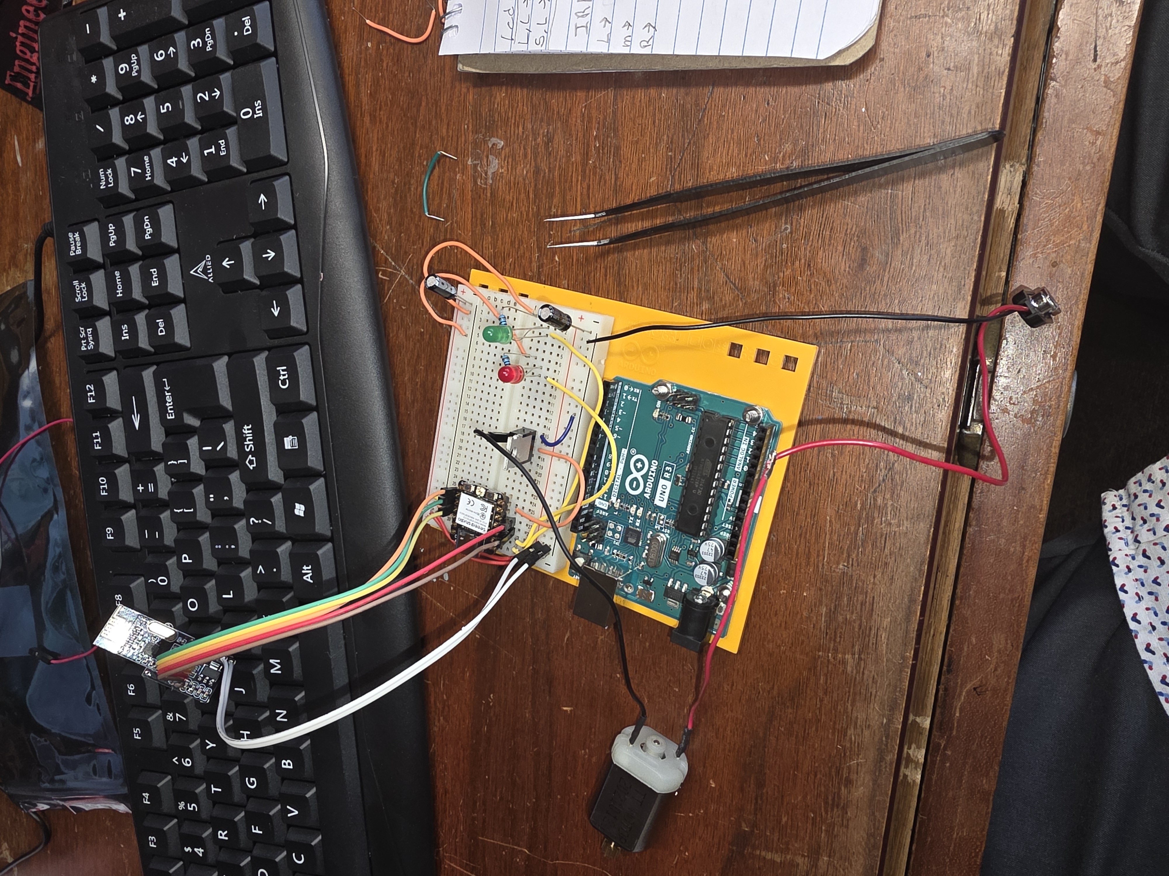
On the ESP32-C3 side, I set up a green LED to indicate when the system was cool and a red LED to show when it was hot. I also added a motor/fan controlled by an IRF540 MOSFET.
When the temperature threshold was reached, the signal from the RP2350 triggered the ESP32-C3 to turn on the red LED and activate the fan. When the system was cool, the green LED stayed on instead.
Programming and Testing
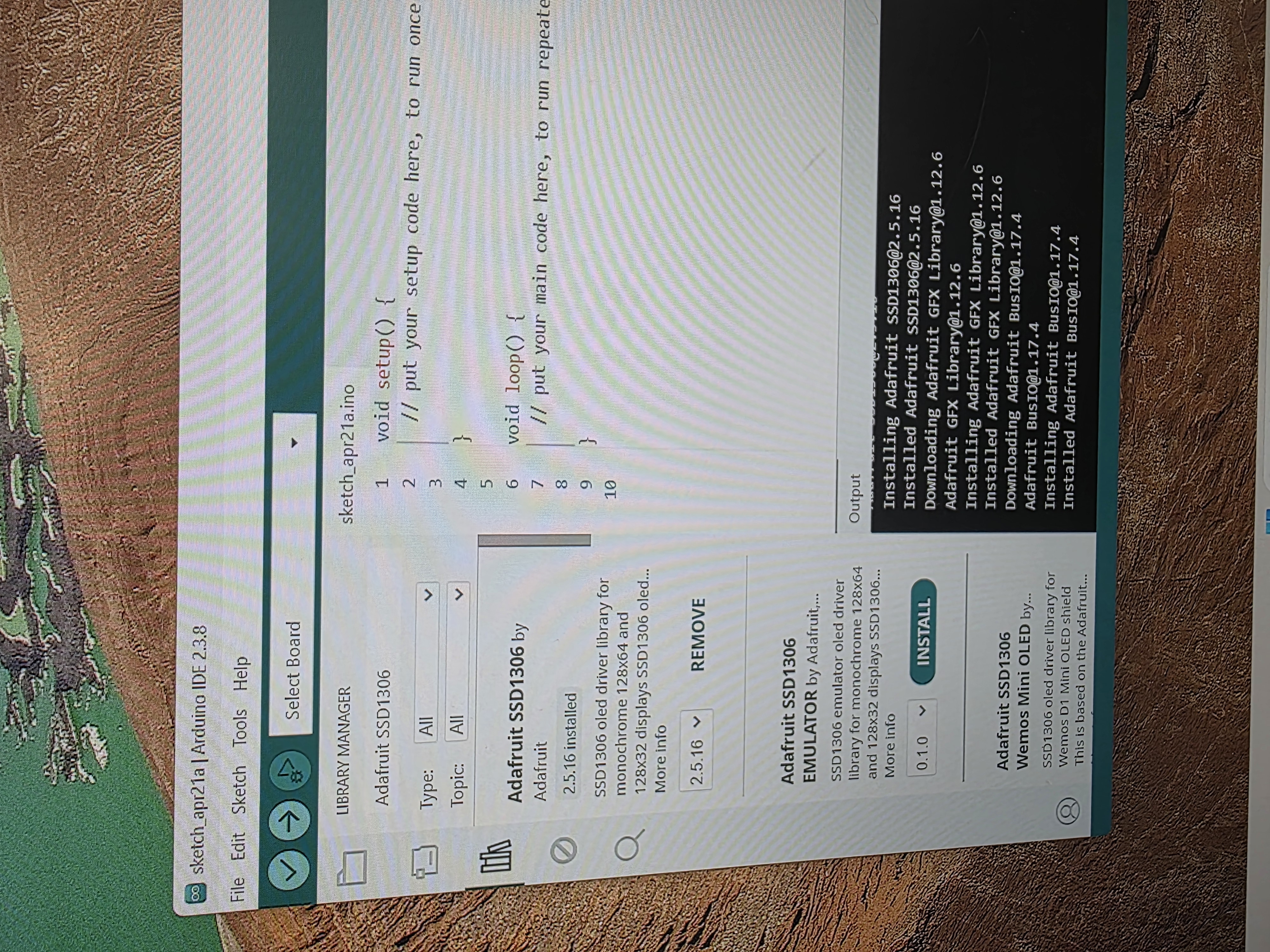
I used the Arduino IDE to code both boards. I already had most of the temperature and output code from previous weeks, so the main challenge was changing the code so the two boards could communicate using the NRF24L01 modules.
Everything worked well after testing and adjusting the code. I had to make sure the transmitter and receiver matched each other, used the correct settings, and responded to the same threshold values.
I also used the Serial Monitor while testing so I could see if the message was being sent and received. That helped a lot because with wireless communication, you cannot physically see the signal moving between the boards.
Networking Setup Images
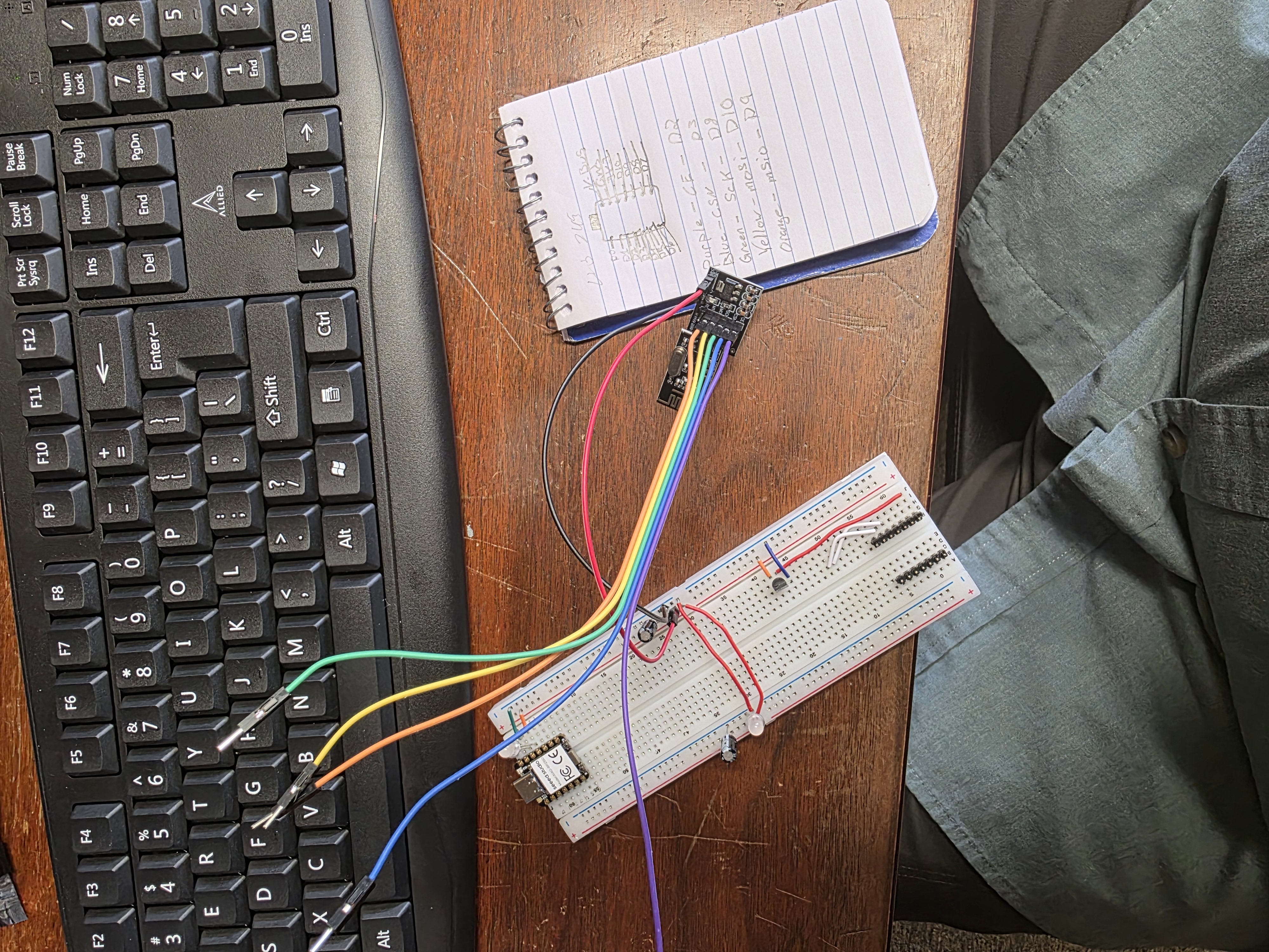
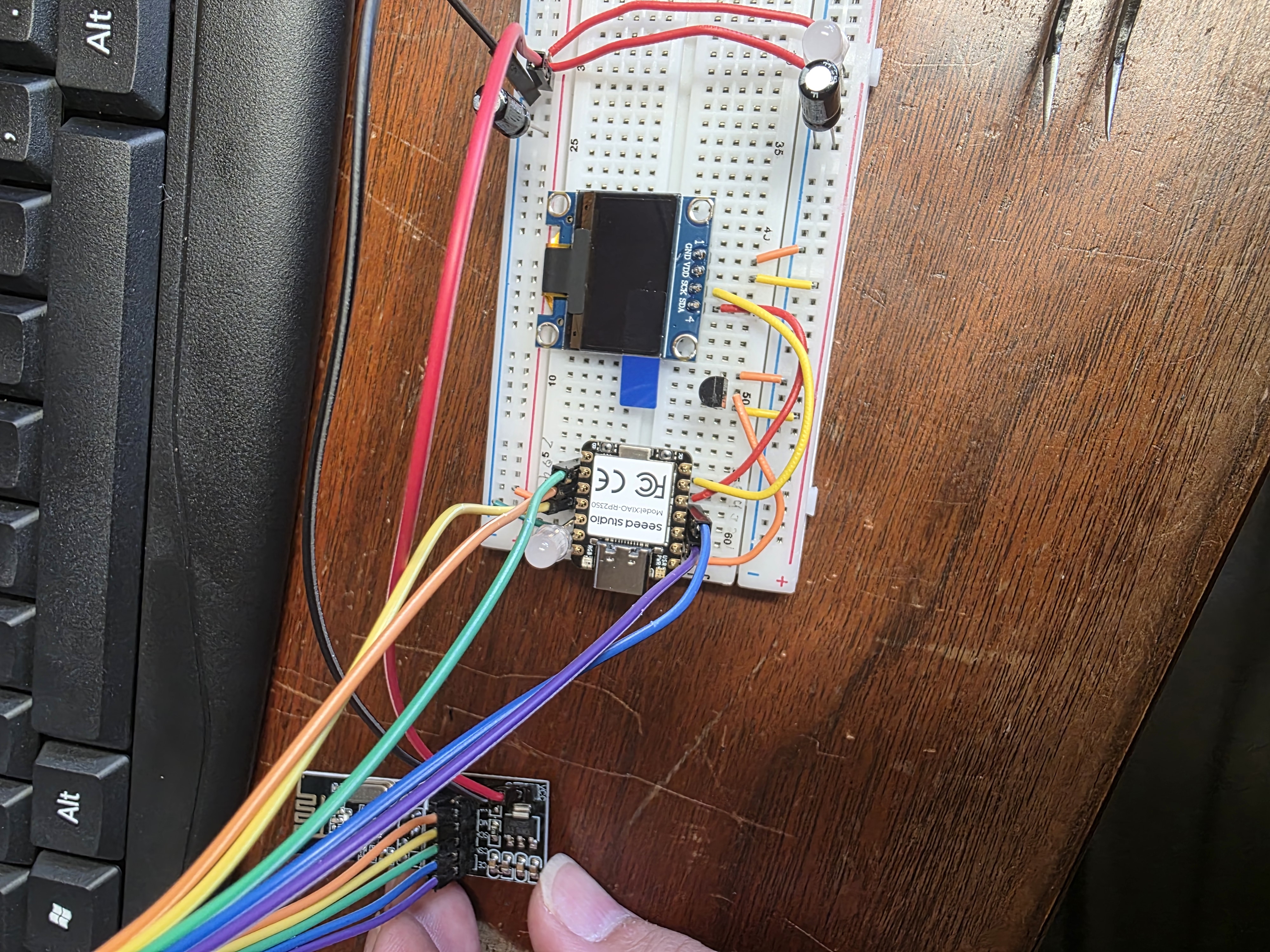
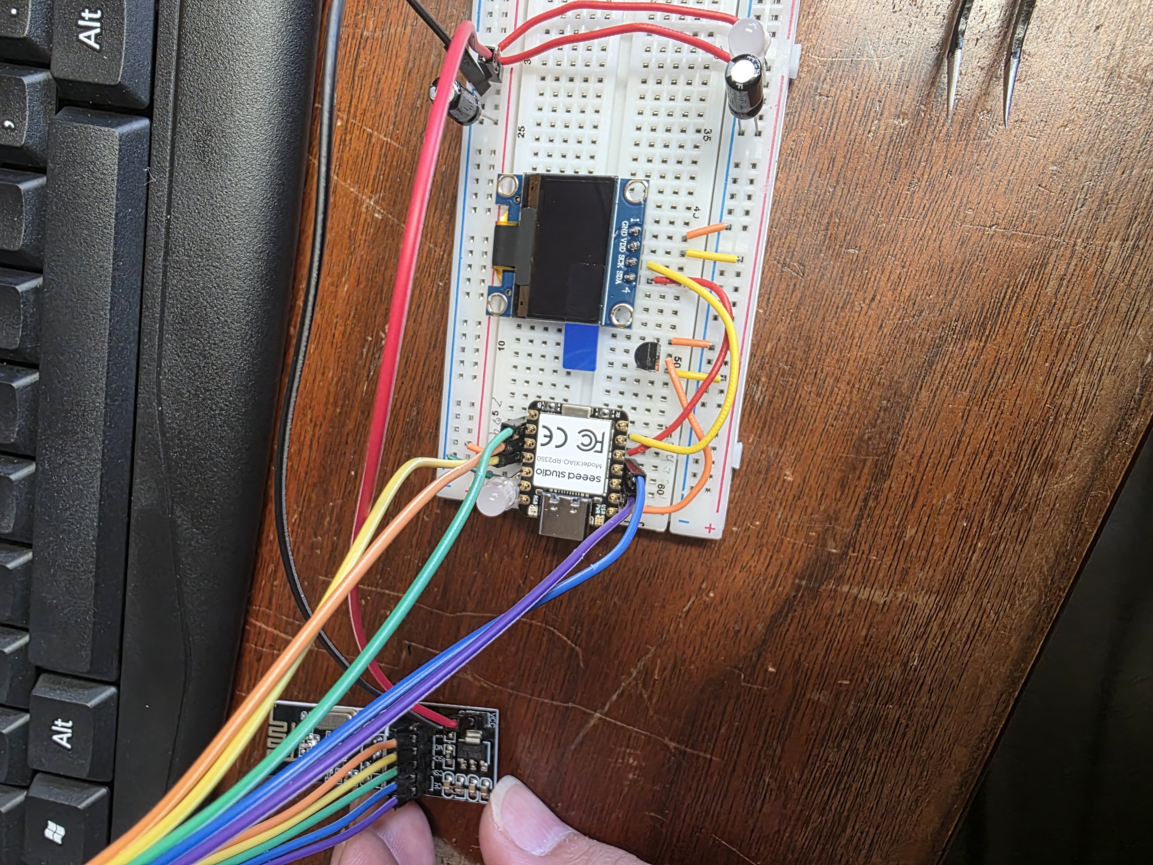
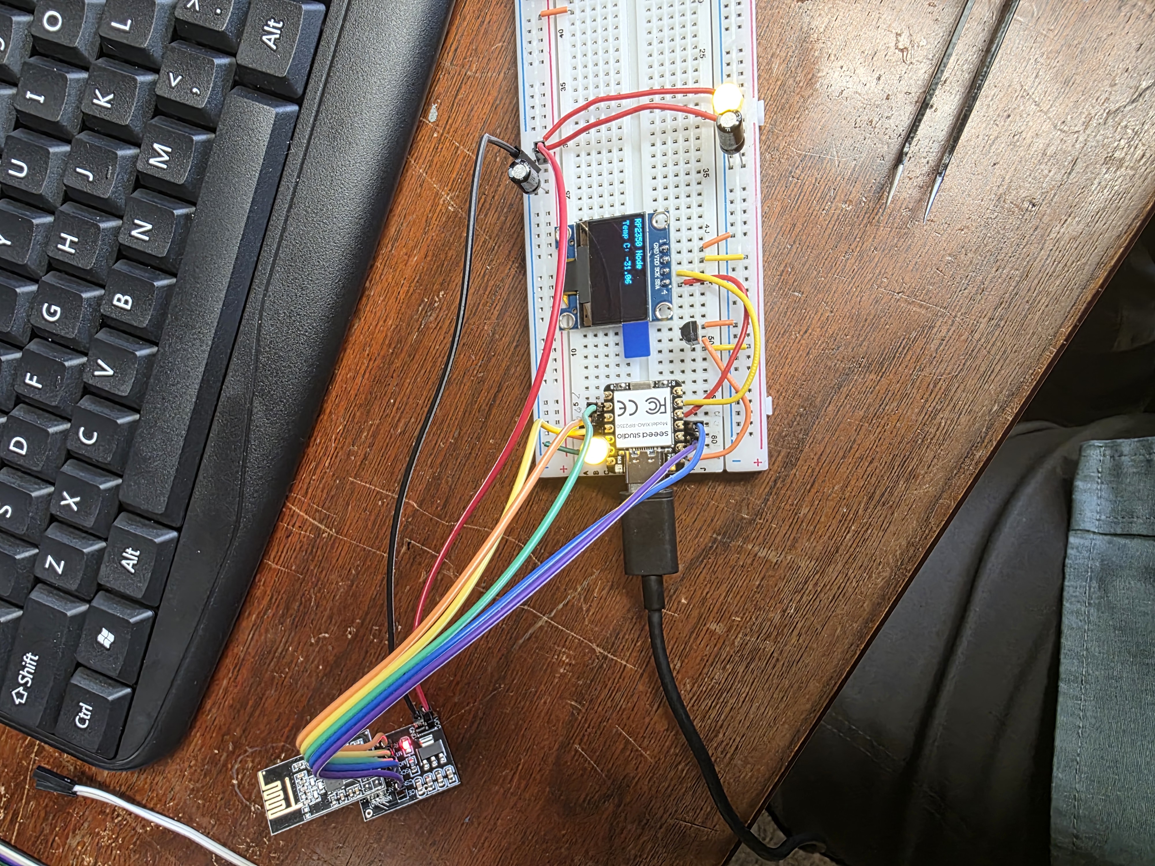
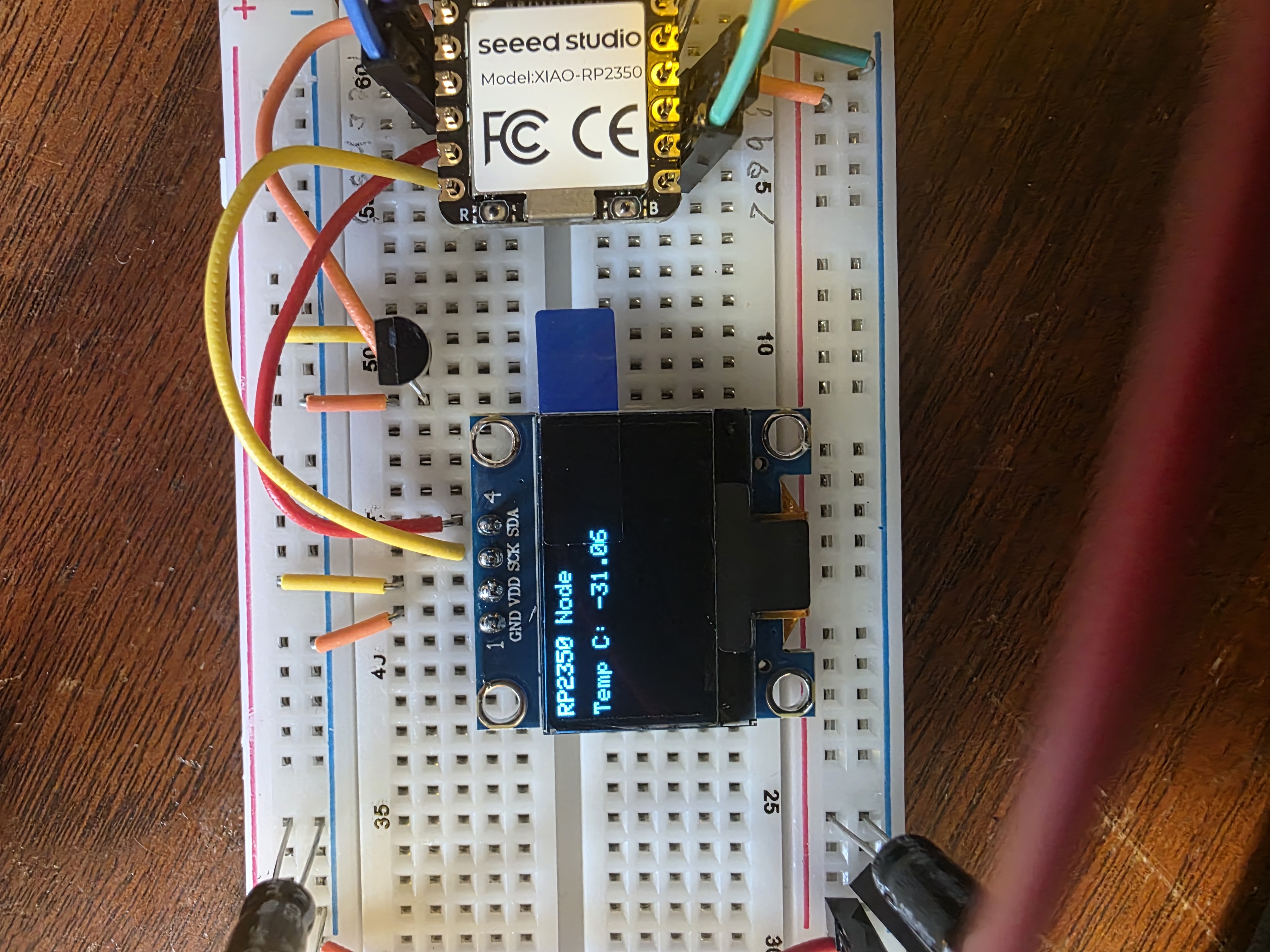
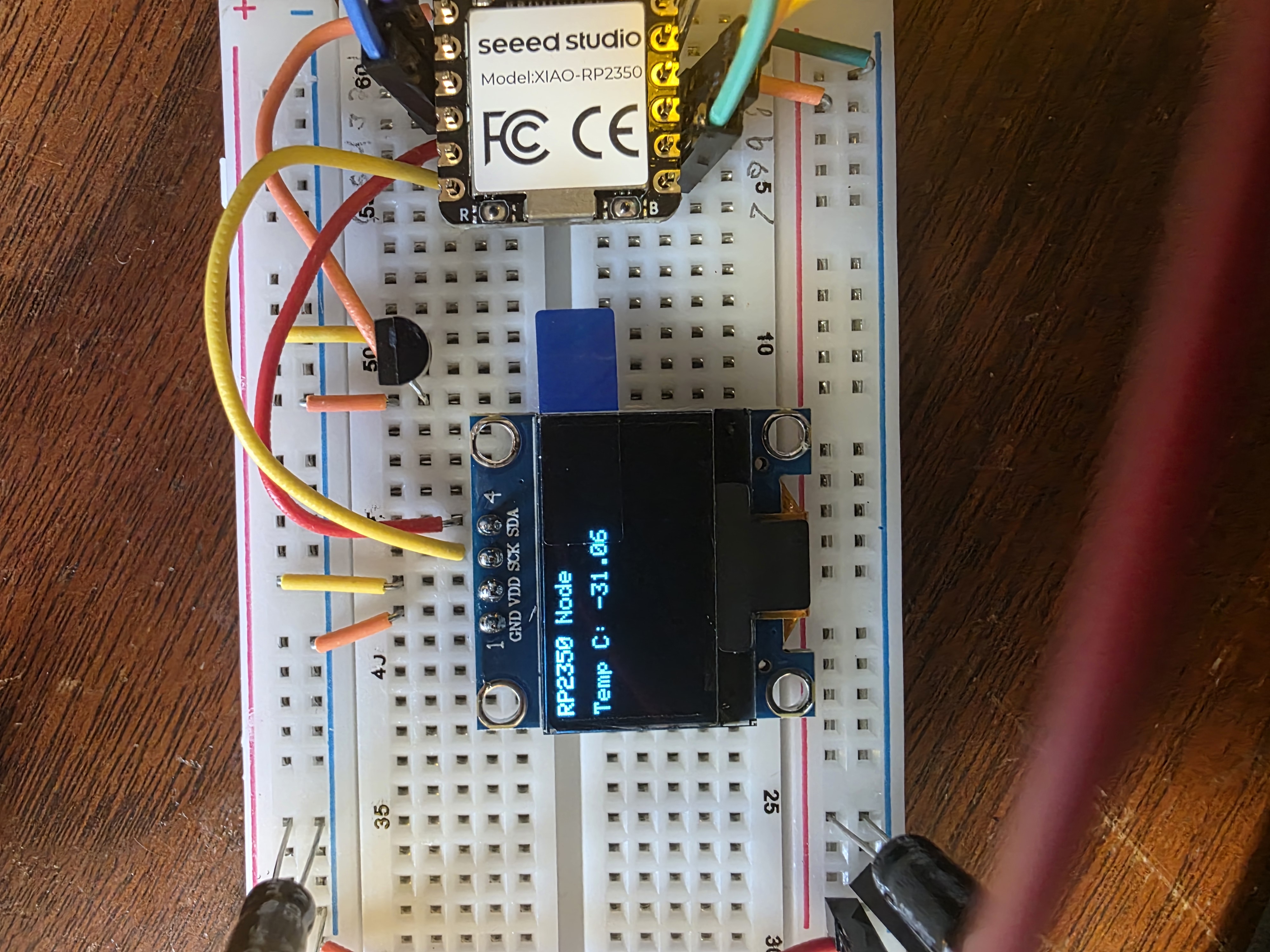
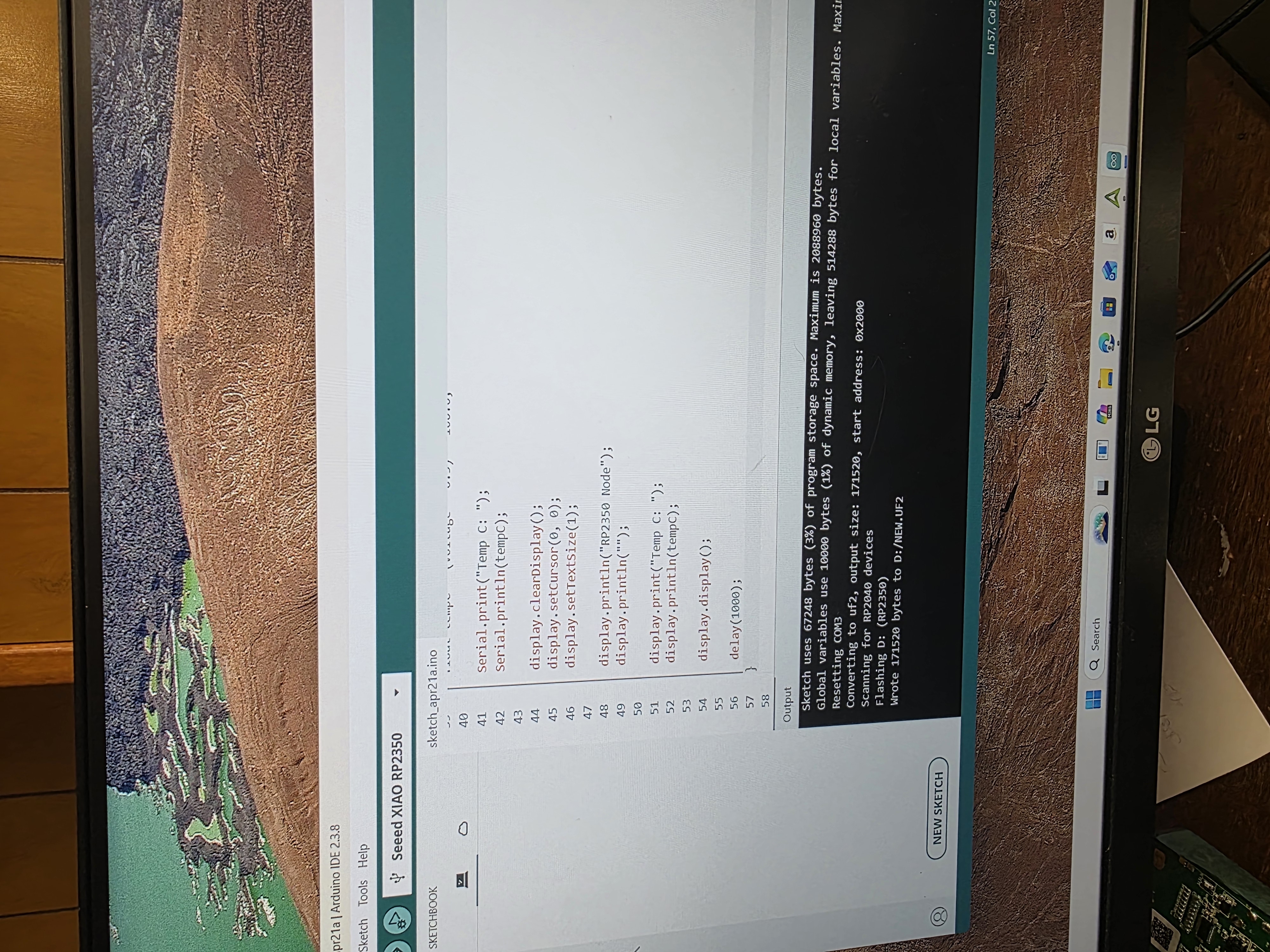
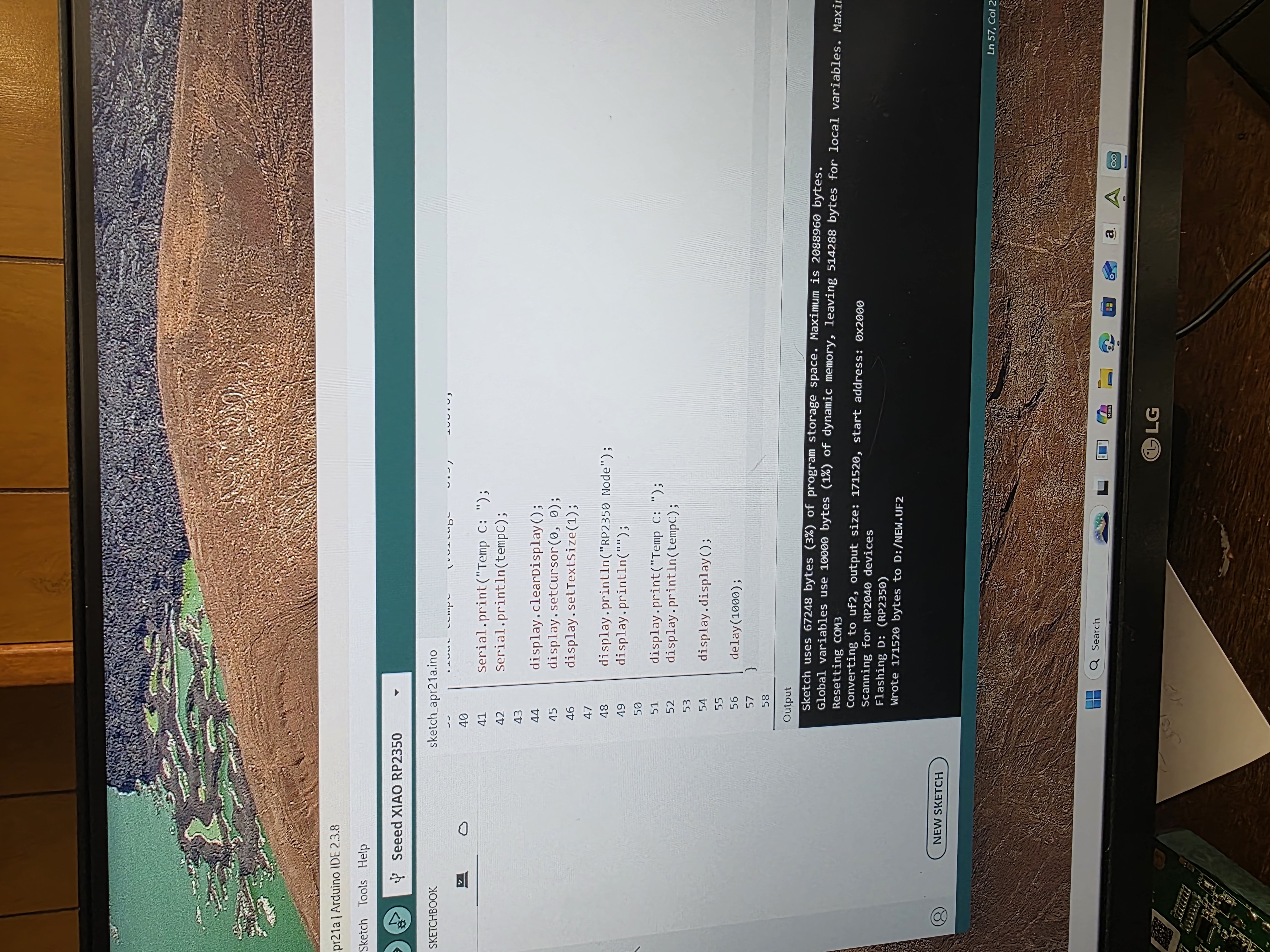
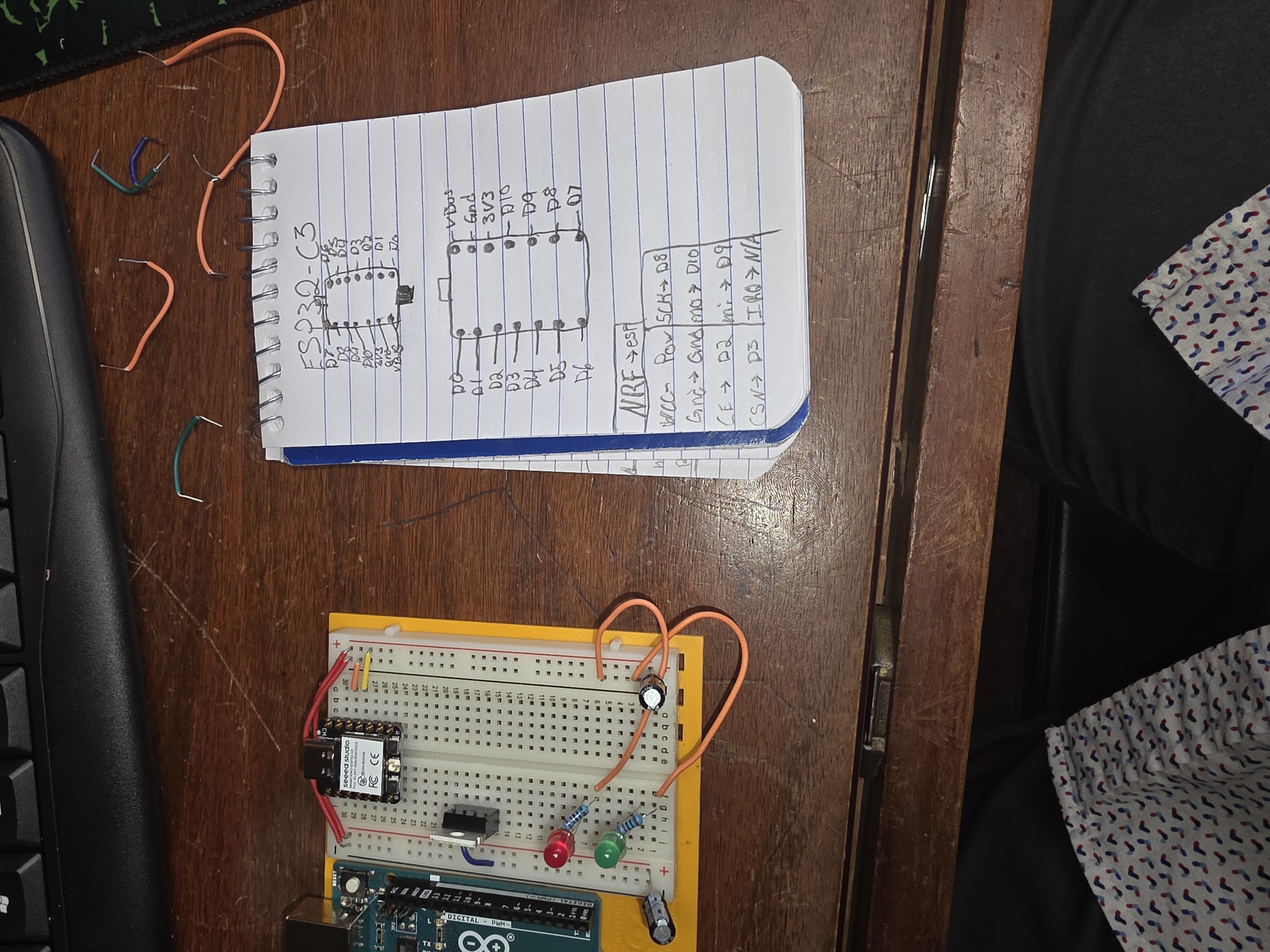
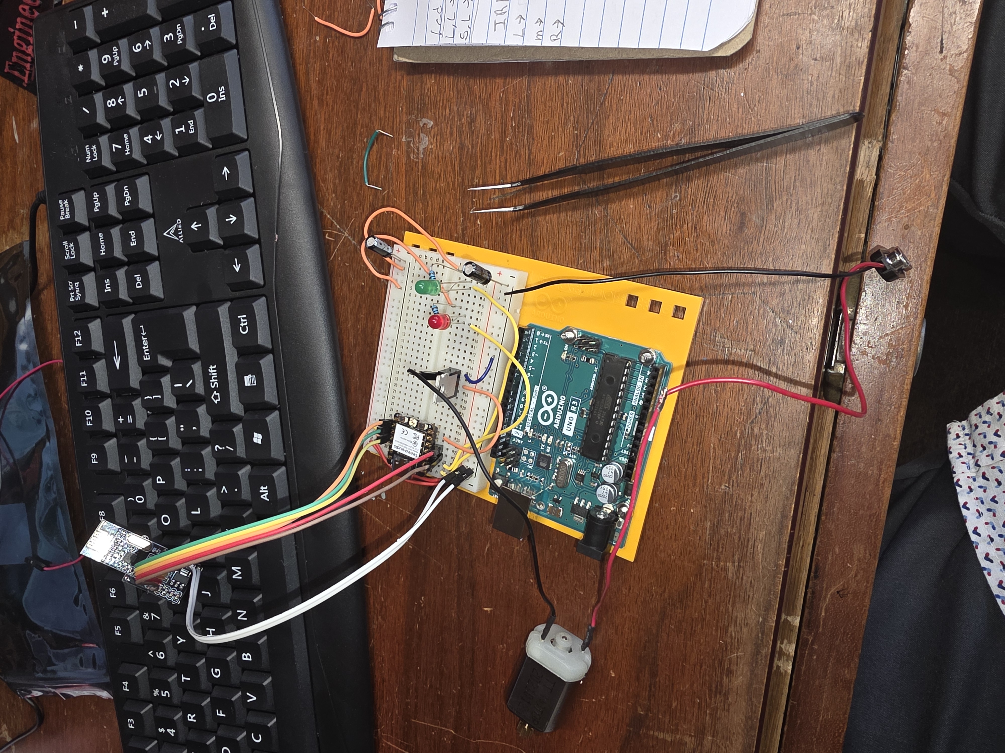
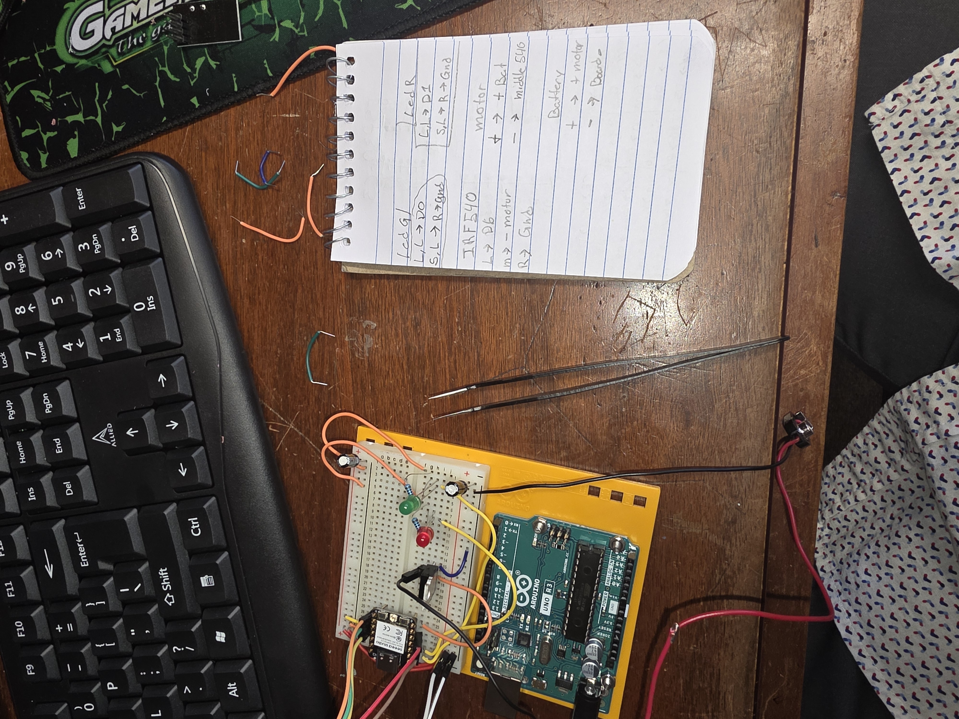
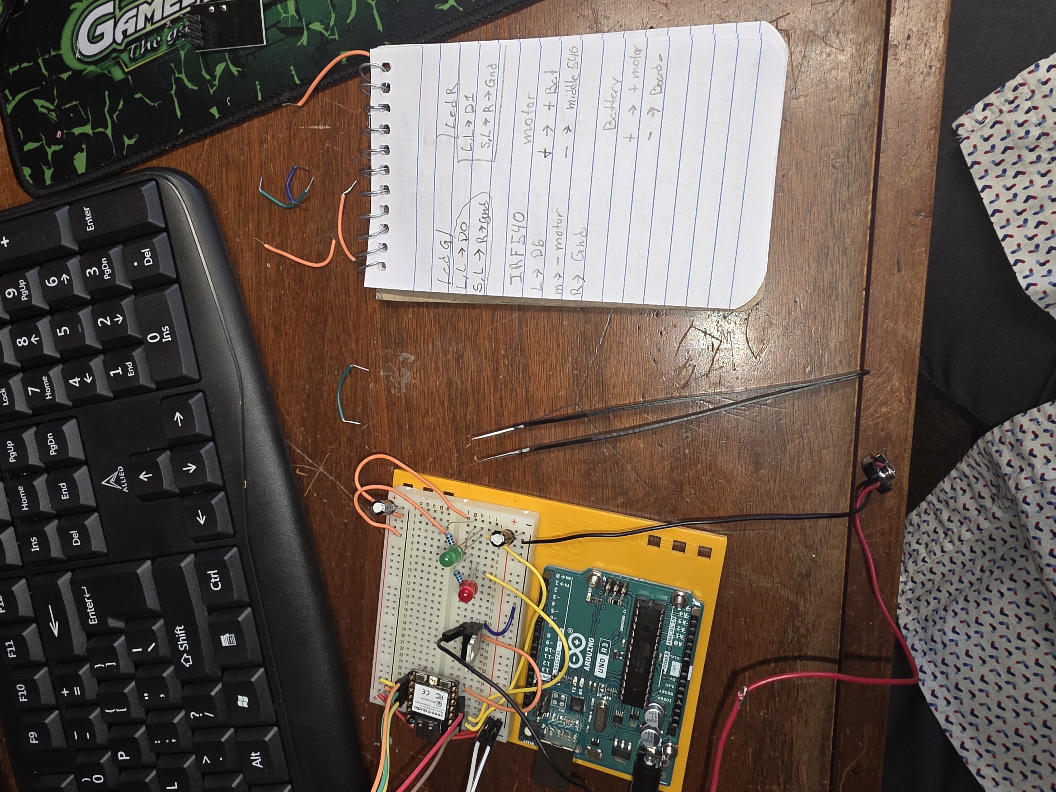
This is showing the temperature going up with just my fingers.

How It Worked
The RP2350 read the temperature sensor first. If the temperature changed, the RP2350 sent that information through the NRF24L01 wireless module. The ESP32-C3 listened for that message with its own NRF24L01 module.
Once the ESP32-C3 received the message, it changed the outputs. If the message said the system was cool, the green LED stayed on. If the message said the system was hot, the red LED turned on and the fan motor turned on.
This made the project work like a small wireless network. The boards had separate jobs, but they worked together. The RP2350 handled the sensing and sending, and the ESP32-C3 handled the receiving and outputs.
Problems I Ran Into
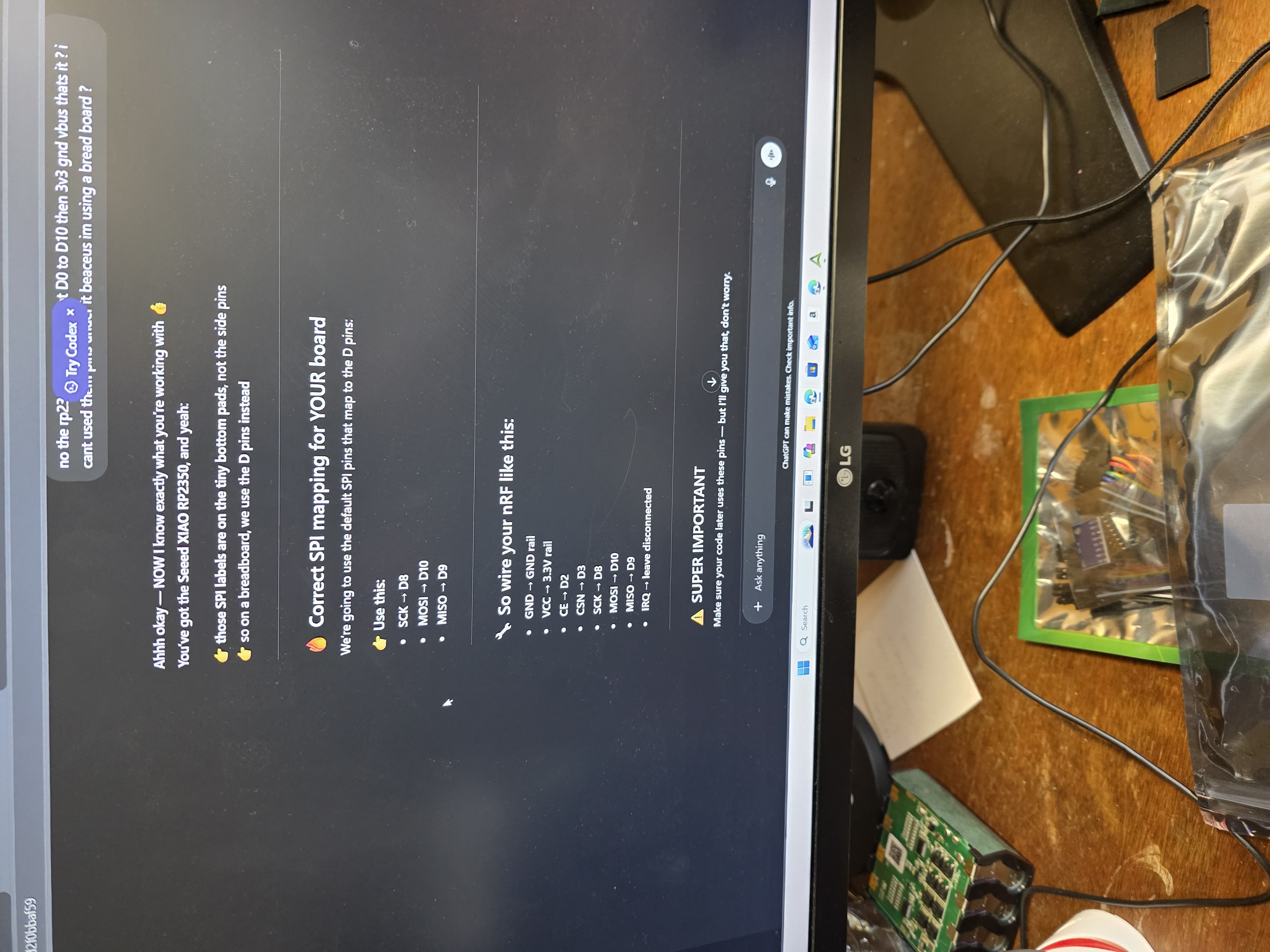
The hardest part was making sure both NRF24L01 modules were wired correctly and using the same settings. If the address, channel, or wiring did not match, the boards would not talk to each other.
I also had to make sure both boards had good power and ground connections. With little wireless modules, one bad connection can make it act like the code is wrong even when the real problem is wiring.
This was different from my earlier projects because now I had to troubleshoot two boards instead of one. I had to check the transmitter, receiver, wireless modules, code, and outputs all at the same time.
What I Learned
This week helped me understand how two microcontrollers can communicate wirelessly and work together as one system. One board collected the input data, and the other board reacted by controlling output devices.
I also learned that wireless communication requires careful wiring, matching code on both sides, and correct threshold values so the transmitter and receiver respond the way I expect.
This assignment also helped connect my previous input and output work together. Instead of one board doing everything, the project was split into two boards that had to talk to each other.