Interface and Application Programming
Building the user interface for my smart battery checker and charger.
Assignments
Group Assignment
- Compare as many tool options as possible.
Individual Assignment
- Write an application that interfaces a user with an input and/or output device that I made.
Group Assignment - Comparing Tool Options
For the group assignment, we compared different tool options that could be used for interface and application programming. This actually connected really well with my final project because I had to figure out the best way for a user to interact with my smart battery checker and charger.
The first tool option I compared was using the Arduino IDE Serial Monitor versus using a real screen interface. The Serial Monitor is good for testing because I can print values like battery voltage and charger mode straight to the computer. The problem is that the project would need a computer connected all the time, and that does not feel like a finished device.
The ESP32 touchscreen was a better option for my final project because the screen lets the user see the voltage, battery status, and charger mode right on the device. That makes the project feel more like a real tool instead of just a test circuit sitting on the bench.
I also compared different controller options. Earlier in Fab Academy I worked with the Arduino Uno R3, Seeed RP2350, Seeed ESP32-C3, and ESP32 boards. The Arduino Uno is simple and easy to use, but it does not have the same interface options. The RP2350 is powerful and worked great for other weeks, but for this project the ESP32 touchscreen made more sense because it combined the microcontroller and display together.
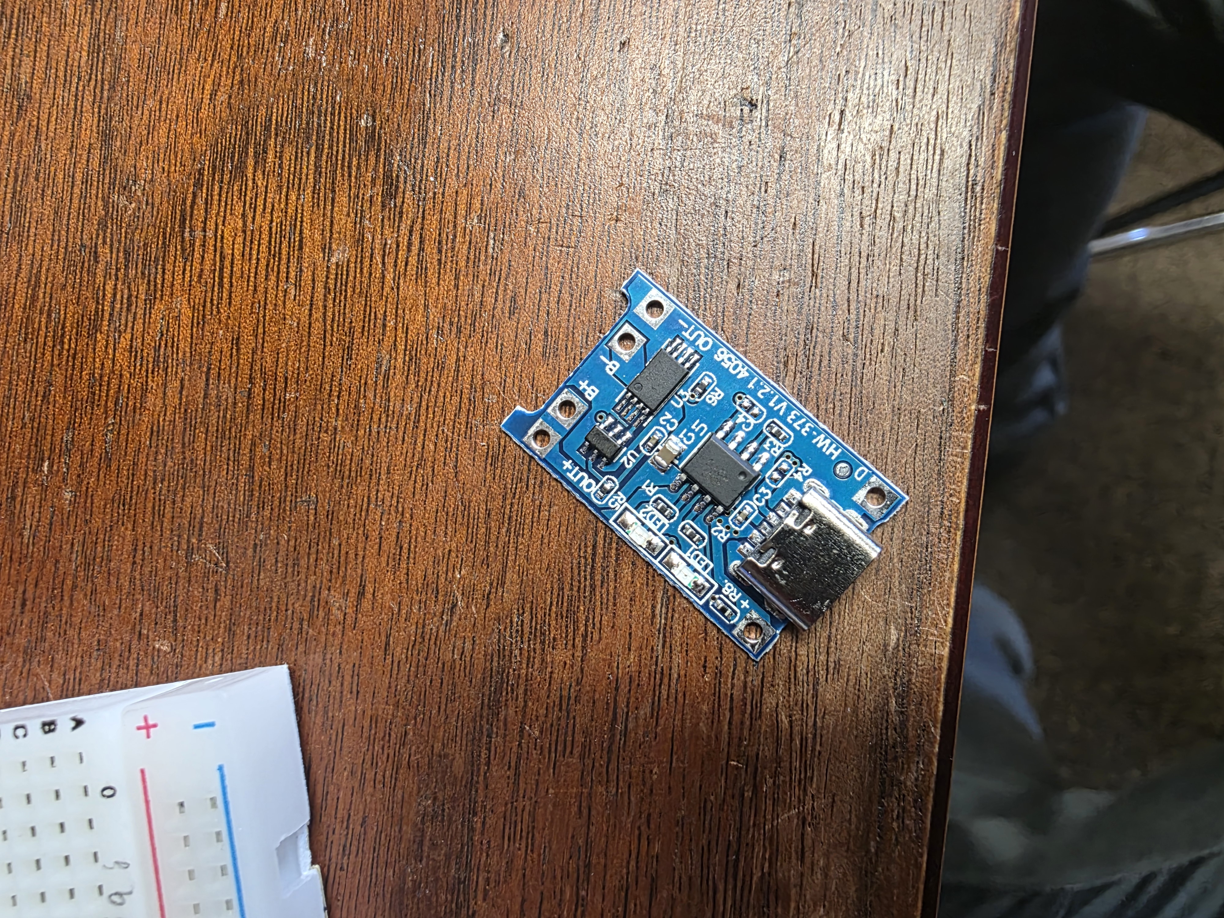
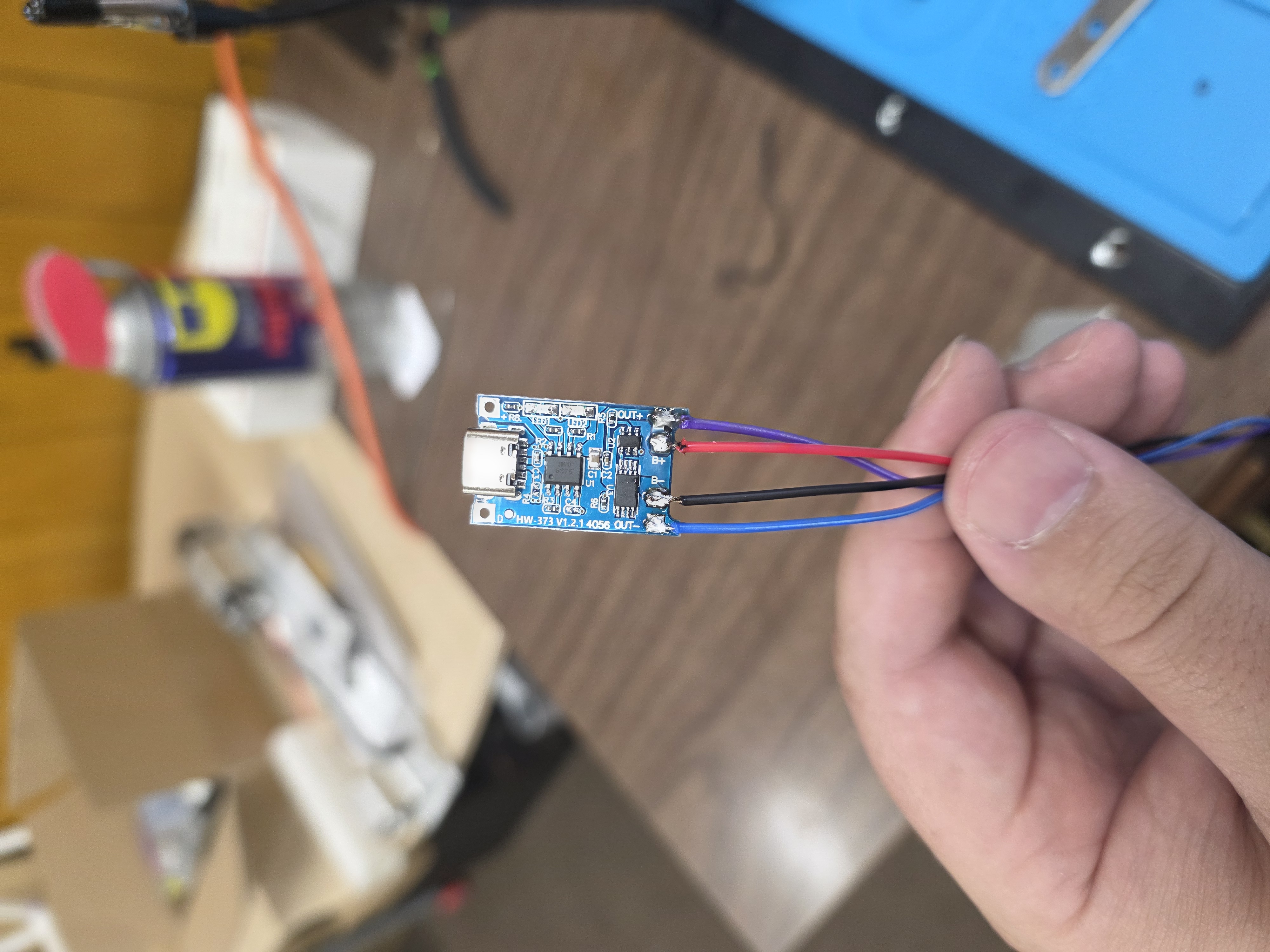
Another thing I compared was the charging setup. For single-cell 3.7V lithium batteries, I used the TP4056 Type-C charger module. For 2S battery packs, I used a separate 2S charger module. These two battery types charge differently, so I kept the charger systems separate and used the interface to switch between modes.
I also compared breadboard wiring versus making a custom PCB. The breadboard was faster for testing code and wiring, but it gets messy fast. The custom PCB is cleaner and better for the final project, but it also means trace spacing, board hold-down, and CNC milling have to be right.
The biggest thing I learned from comparing tools is that the best tool depends on the job. For testing, the Serial Monitor and breadboard are great. For the final version, the ESP32 touchscreen and custom PCB make the project easier to use and more like a finished product.
Individual Assignment - Final Project User Interface
For Week 15, the assignment was to write an application that interfaces a user with an input and/or output device that I made. For this week, I worked on the user interface for my final project, which is a smart battery checker and charger.
The goal of this application is to let the user interact with the battery checker through an ESP32 touchscreen and a button. The project reads battery voltage through two resistors used as a voltage divider, displays the voltage on the screen, and allows the user to switch between different charging modes for different battery types.
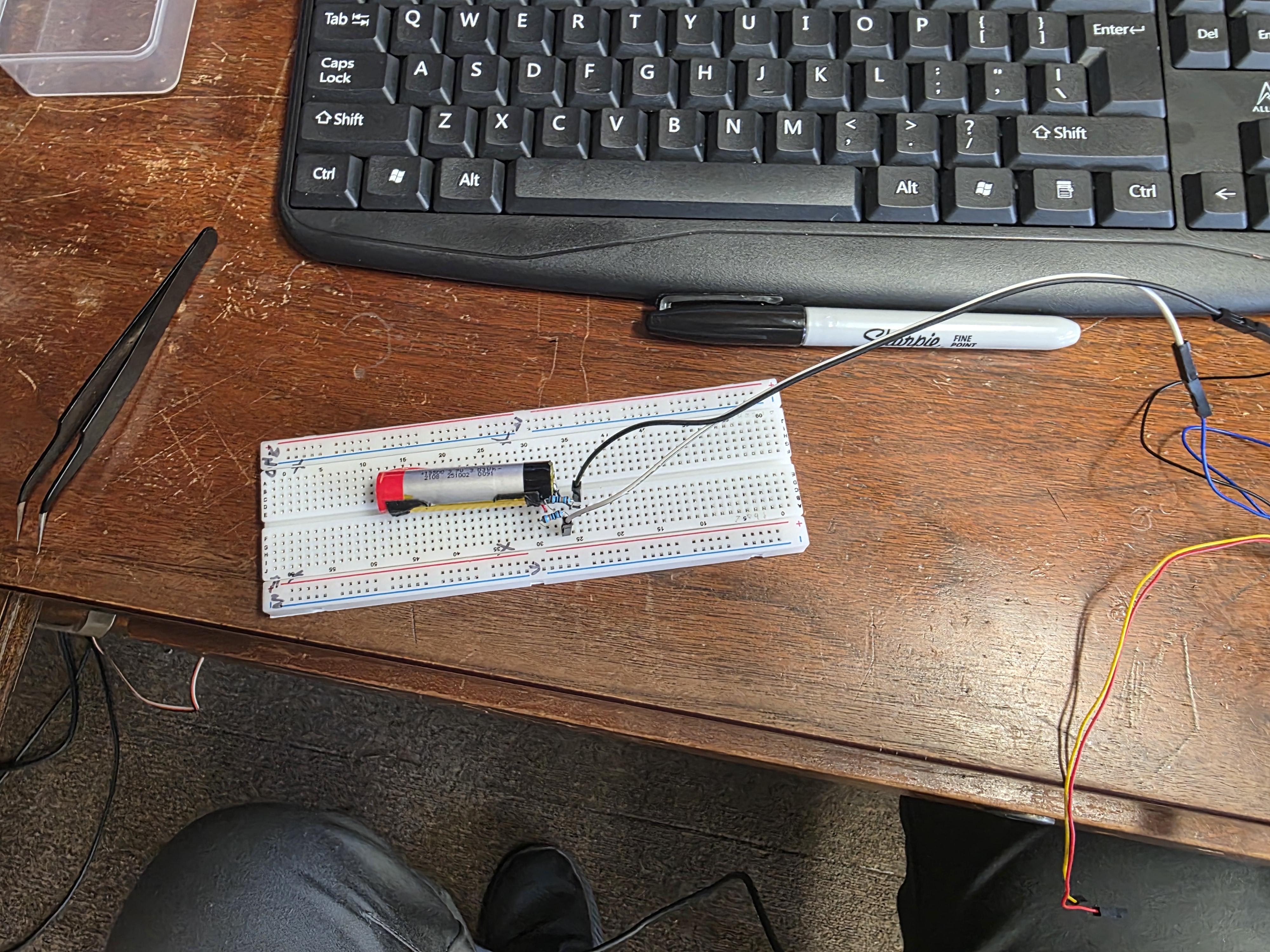
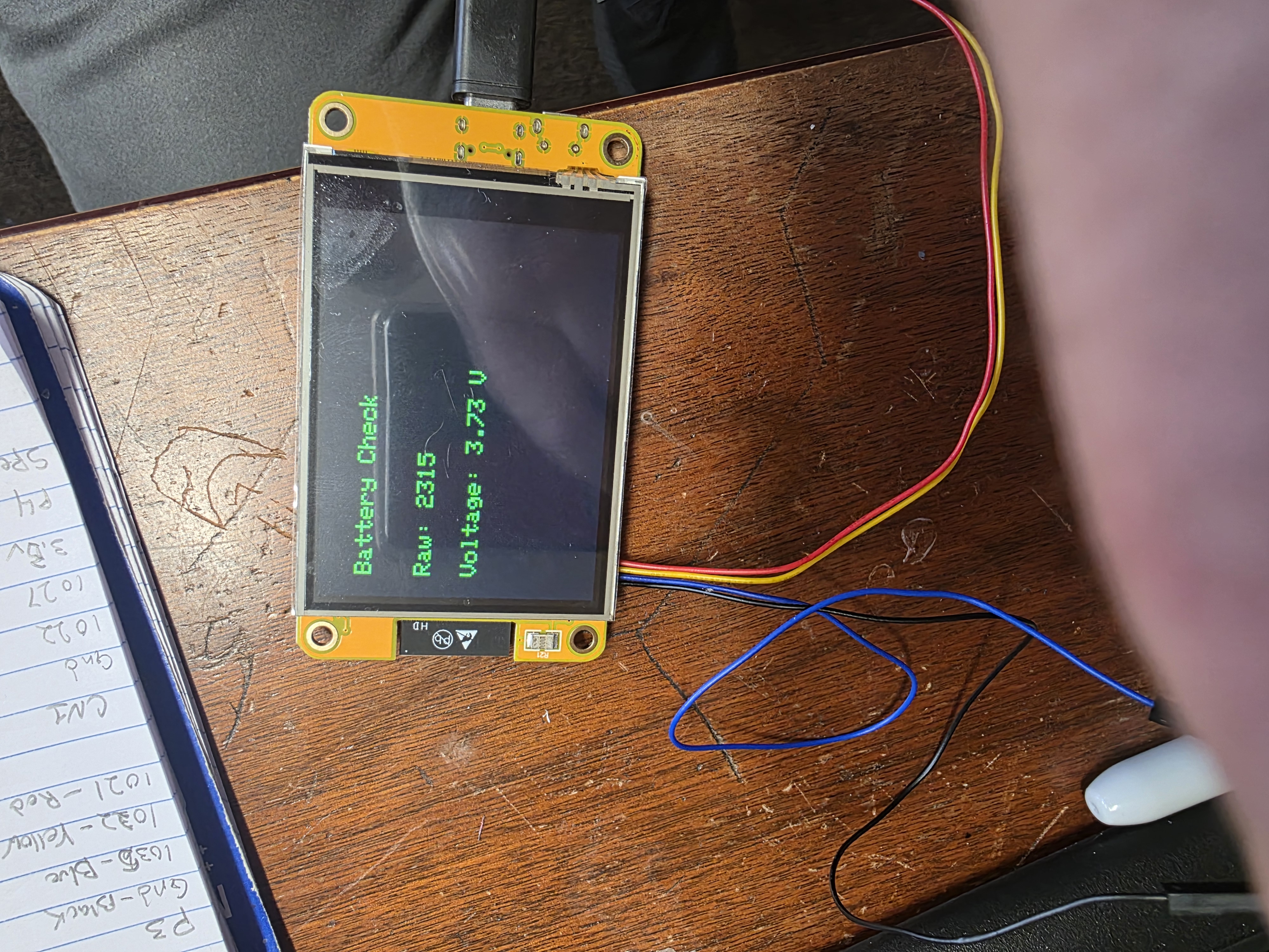
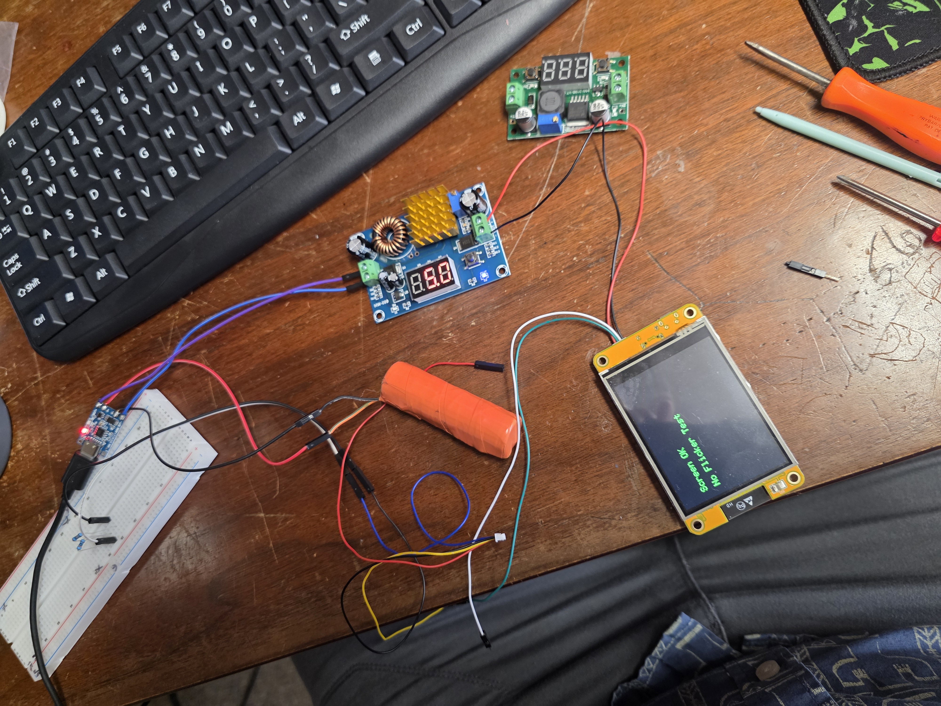
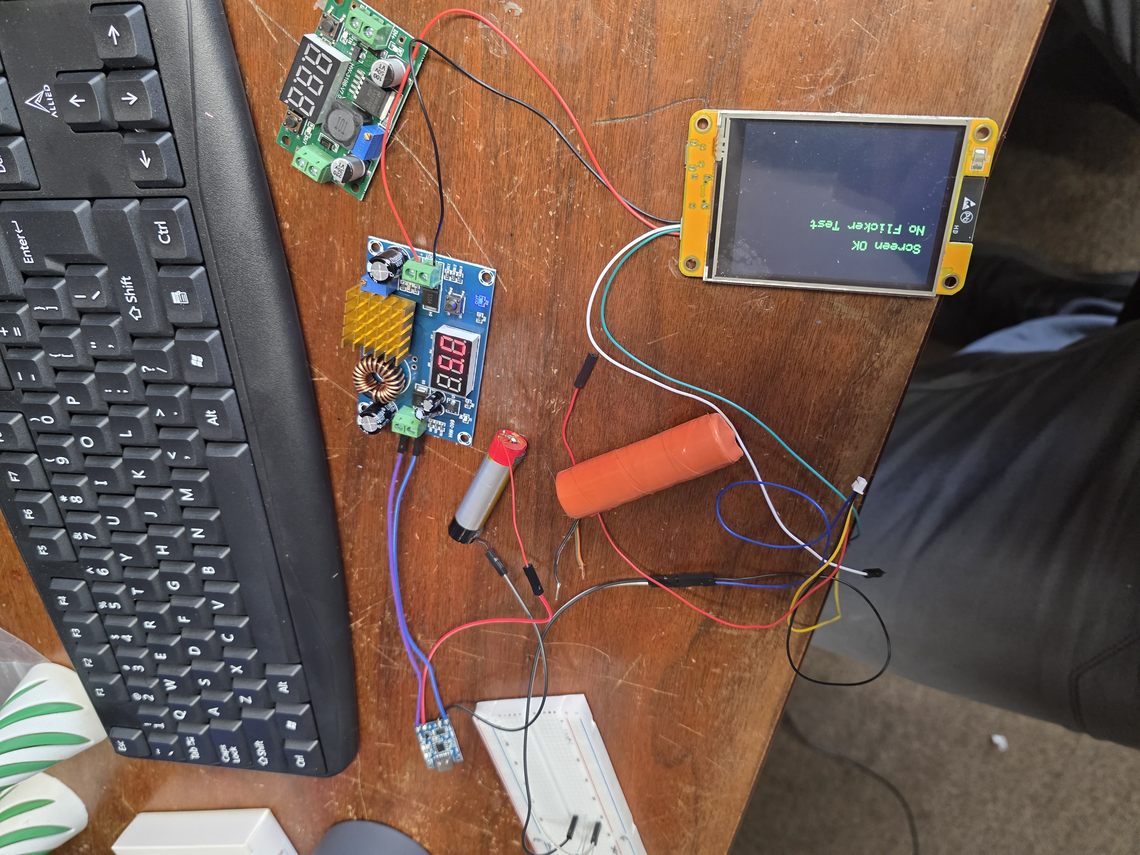
For my final project, I am using the ESP32 touchscreen as the main interface. The screen acts as the output device because it shows the battery voltage, charger mode, and battery status. The input device is a button that lets the user switch between the different charger modules or battery modes.
What the Project Does
The smart battery checker and charger is designed to check and charge different types of lithium batteries. One mode is for a single-cell 3.7V lithium battery using a TP4056 charging module. The other mode is for a 2S lithium battery pack, which is around 7.4V nominal and 8.4V fully charged, using a separate 2S charger module.
The two charger modules are kept separate so their outputs do not touch each other. The button allows the user to switch the screen between modes, so the display knows which battery type the user is checking or charging.
Components Used
- ESP32 touchscreen display
- TP4056 Type-C charger module for 3.7V lithium batteries
- 2S charger module for 7.4V lithium battery packs
- Two resistors used as a voltage divider
- Push button for switching modes
- Battery holders and battery wires
- Custom PCB wiring layout
- Buck and boost converter modules for power testing
- Arduino IDE for writing and uploading the code
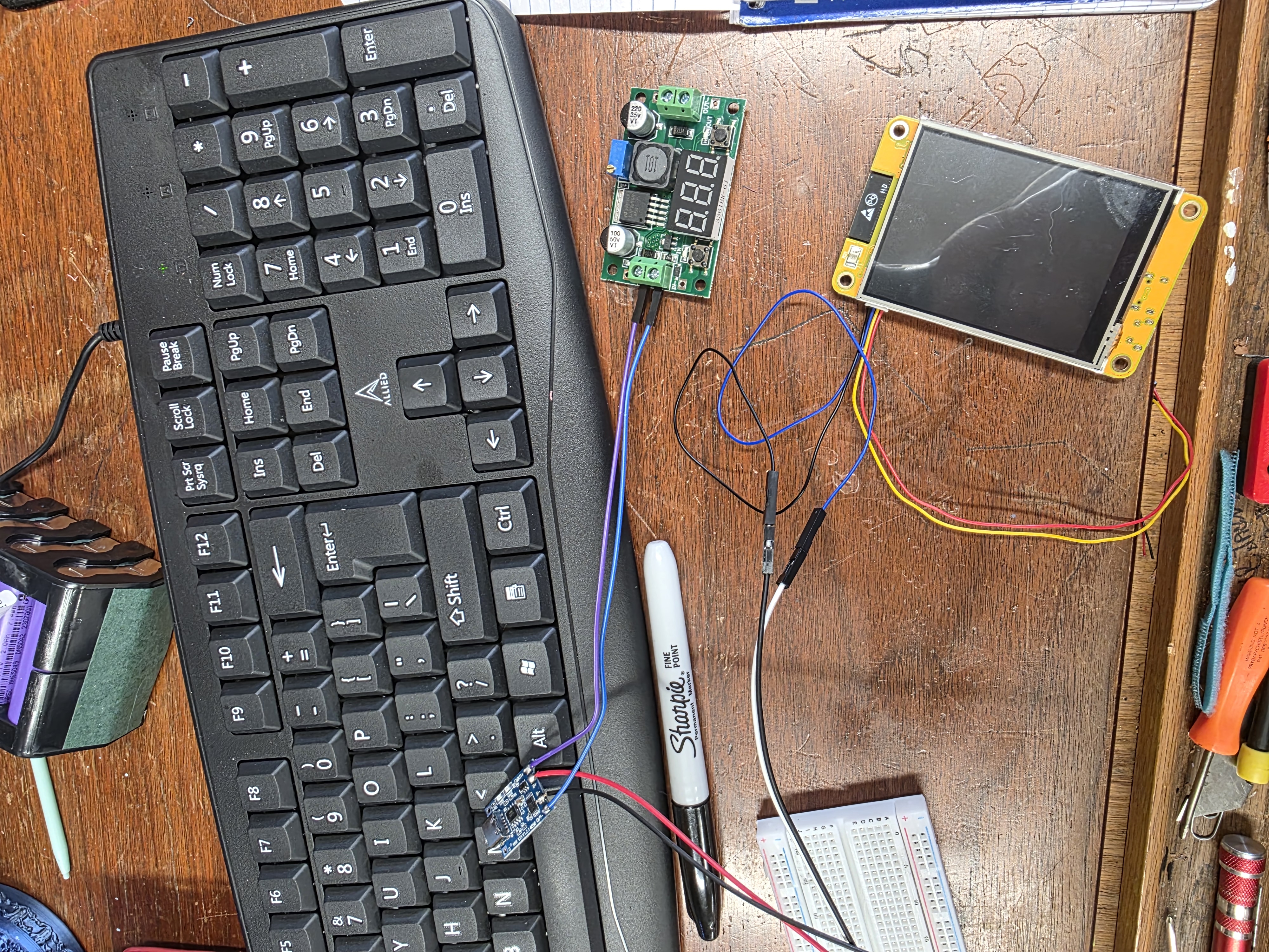
How the Code Works
The code was written in the Arduino IDE. The ESP32 reads the battery voltage from an analog input pin. Since the ESP32 cannot safely read higher battery voltages directly, I used two resistors as a voltage divider. The voltage divider lowers the battery voltage to a safe level for the ESP32 analog pin.
The code then converts the analog reading into a real voltage value. After that, the screen displays the battery voltage and gives the user information about the battery status. The button changes the mode on the screen, so the user can switch between the single-cell charger mode and the 2S charger mode.
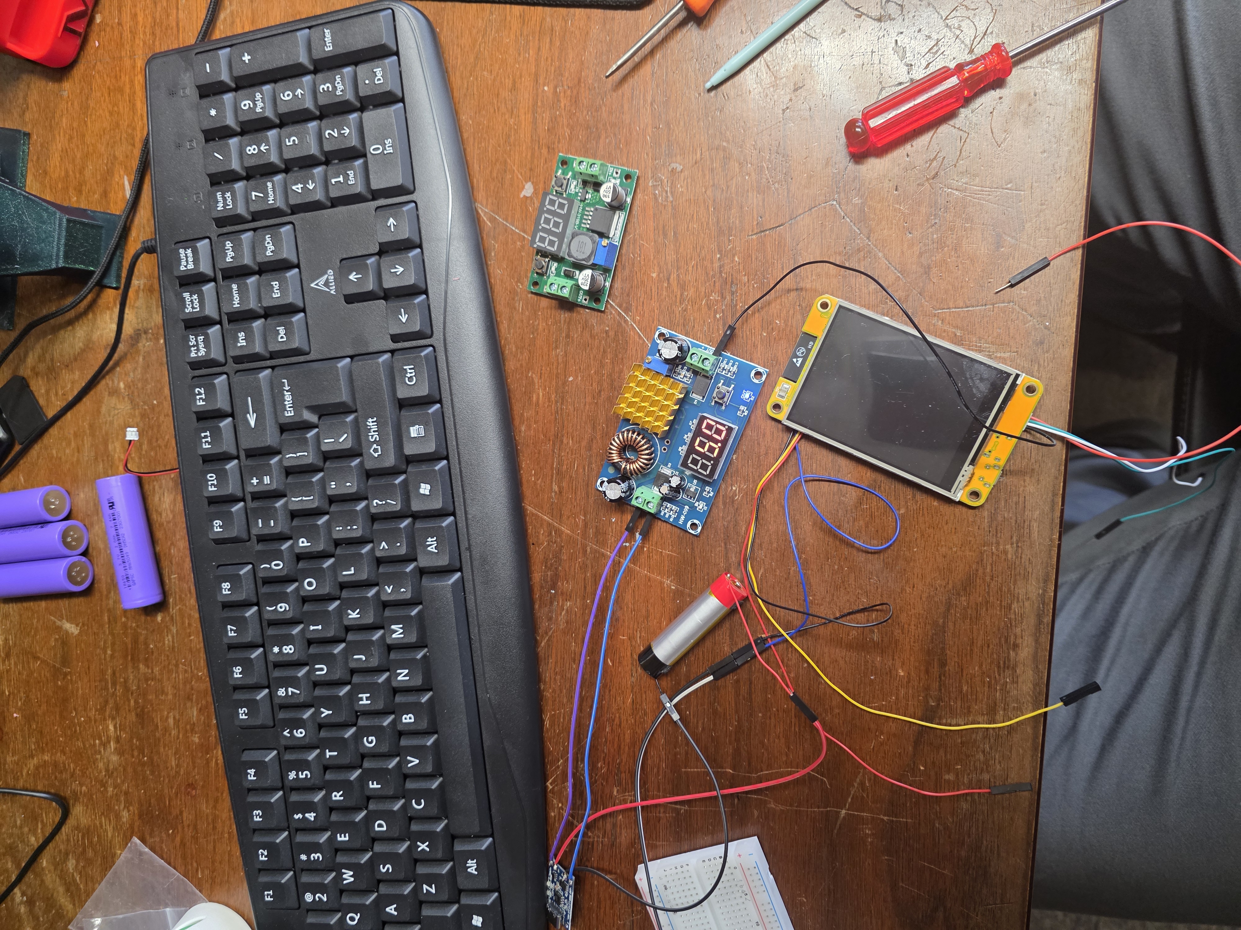
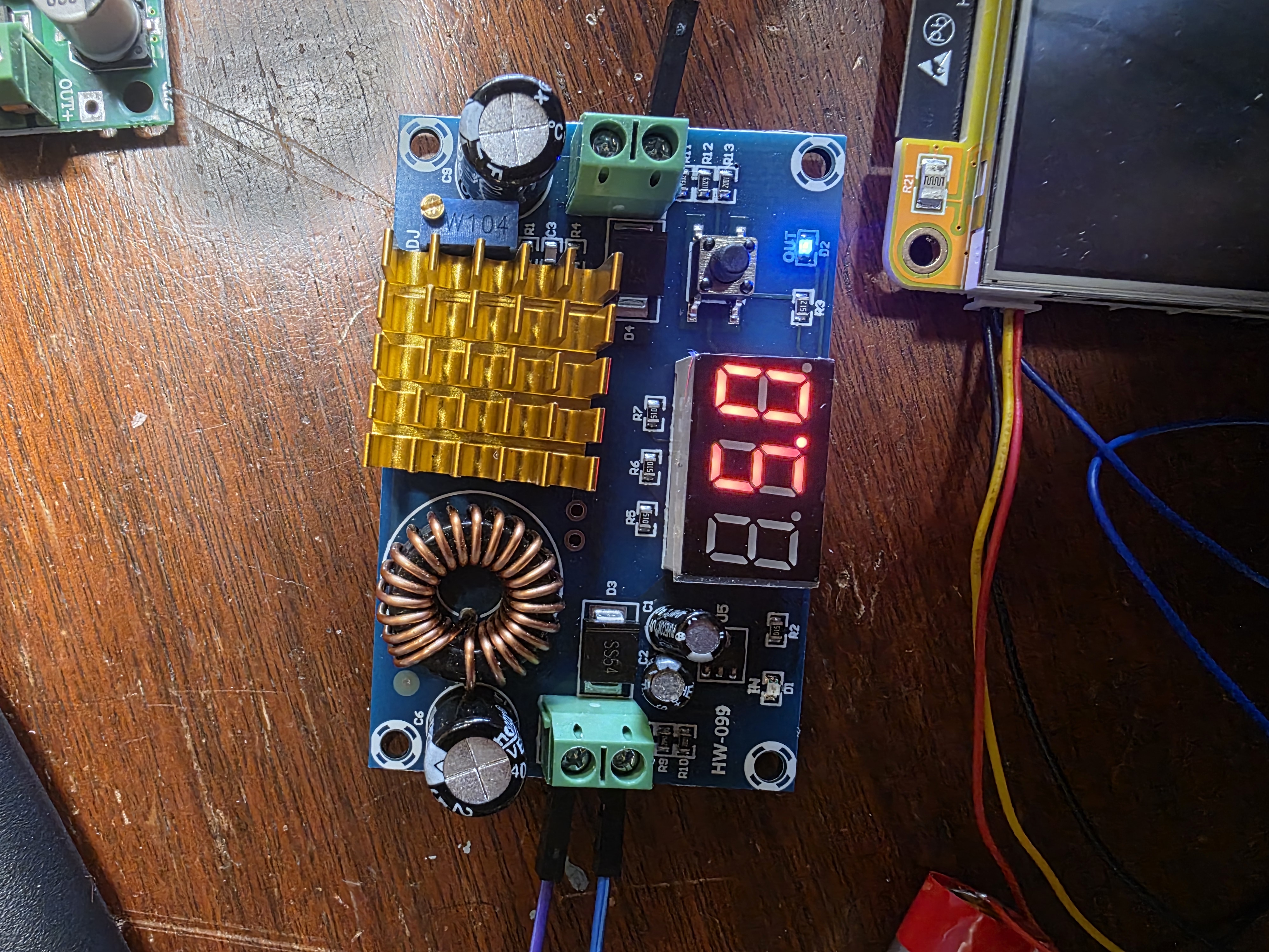
Sample Arduino Code
This is a small sample of the type of code used to read the battery voltage through the resistor divider and switch between charger modes using a button.
const int batteryPin = 35;
const int buttonPin = 22;

float resistor1 = 100000.0;
float resistor2 = 33000.0;

int chargerMode = 0;
bool lastButtonState = HIGH;

void setup() {
  Serial.begin(115200);

  pinMode(buttonPin, INPUT_PULLUP);

  // Screen setup would go here
}

void loop() {
  bool buttonState = digitalRead(buttonPin);

  if (lastButtonState == HIGH && buttonState == LOW) {
    chargerMode++;

    if (chargerMode > 1) {
      chargerMode = 0;
    }

    delay(250);
  }

  lastButtonState = buttonState;

  int rawValue = analogRead(batteryPin);

  float adcVoltage = rawValue * (3.3 / 4095.0);

  float batteryVoltage = adcVoltage * ((resistor1 + resistor2) / resistor2);

  Serial.print("Battery Voltage: ");
  Serial.println(batteryVoltage);

  if (chargerMode == 0) {
    Serial.println("Mode: 1S 3.7V Battery / TP4056 Charger");
  }

  if (chargerMode == 1) {
    Serial.println("Mode: 2S 7.4V Battery / 2S Charger Module");
  }

  delay(500);
}
This code reads the voltage, calculates the real battery voltage, and changes modes when the button is pressed. In the final version, the Serial Monitor information will also be shown on the touchscreen display so the user can see the battery information without needing a computer.
Screen Interface
The screen is important because it makes the project easier to use. Instead of only reading values in the Arduino Serial Monitor, the user will be able to see the battery voltage and charger mode directly on the device. This makes the project feel more like a finished tool instead of just a test circuit.
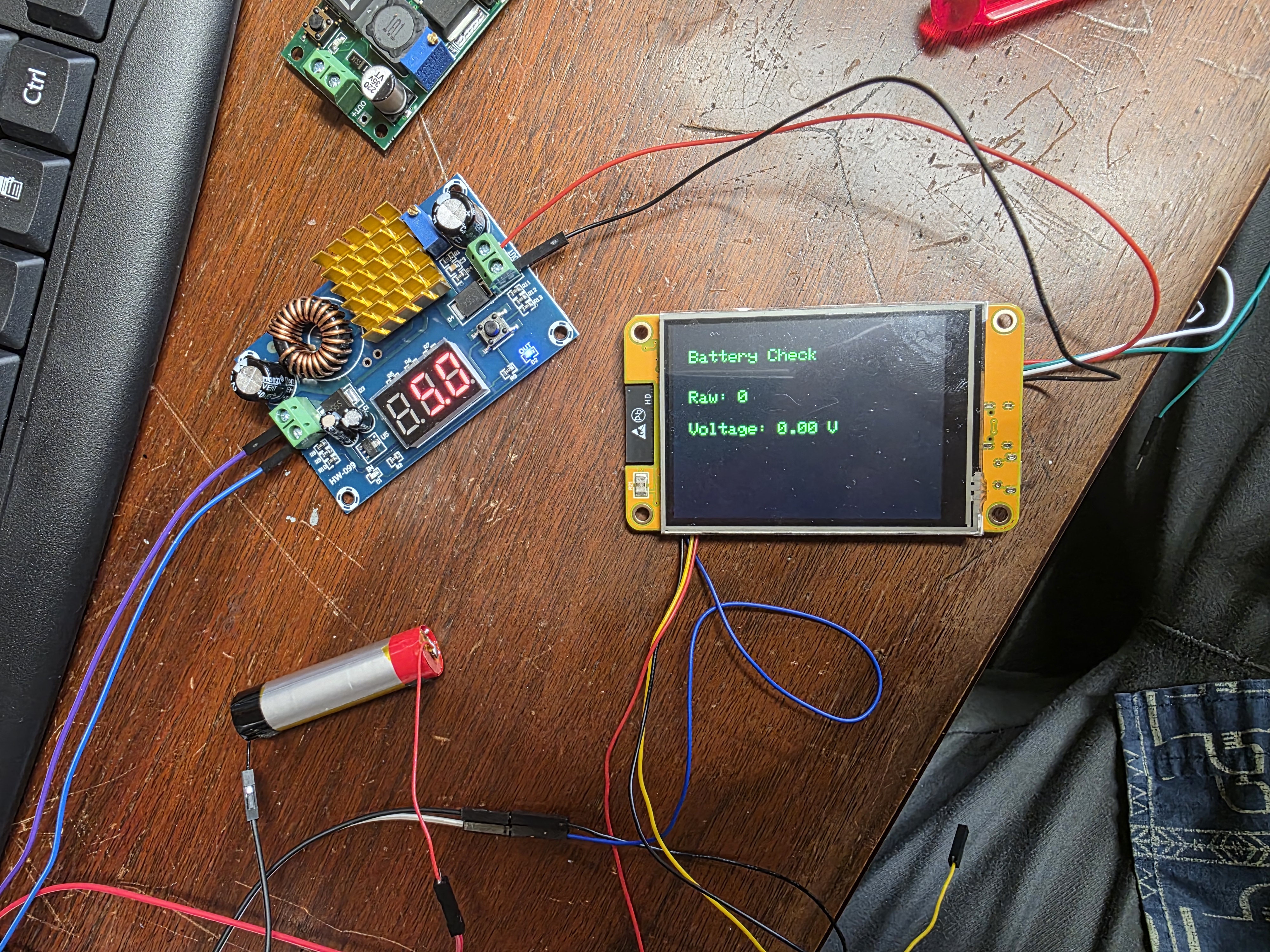
Custom PCB Development
As part of the final project, I also started designing and milling a custom PCB for the smart battery checker and charger. The goal of the PCB is to combine the ESP32, battery voltage reading circuit, button input, and charging connections into one clean board instead of using loose breadboard wires.
The PCB was designed with traces for the battery voltage divider, charger module connections, screen connections, and button input for switching between charging modes. I used larger traces where possible so the Makera Carvera CNC machine could mill the board more reliably.
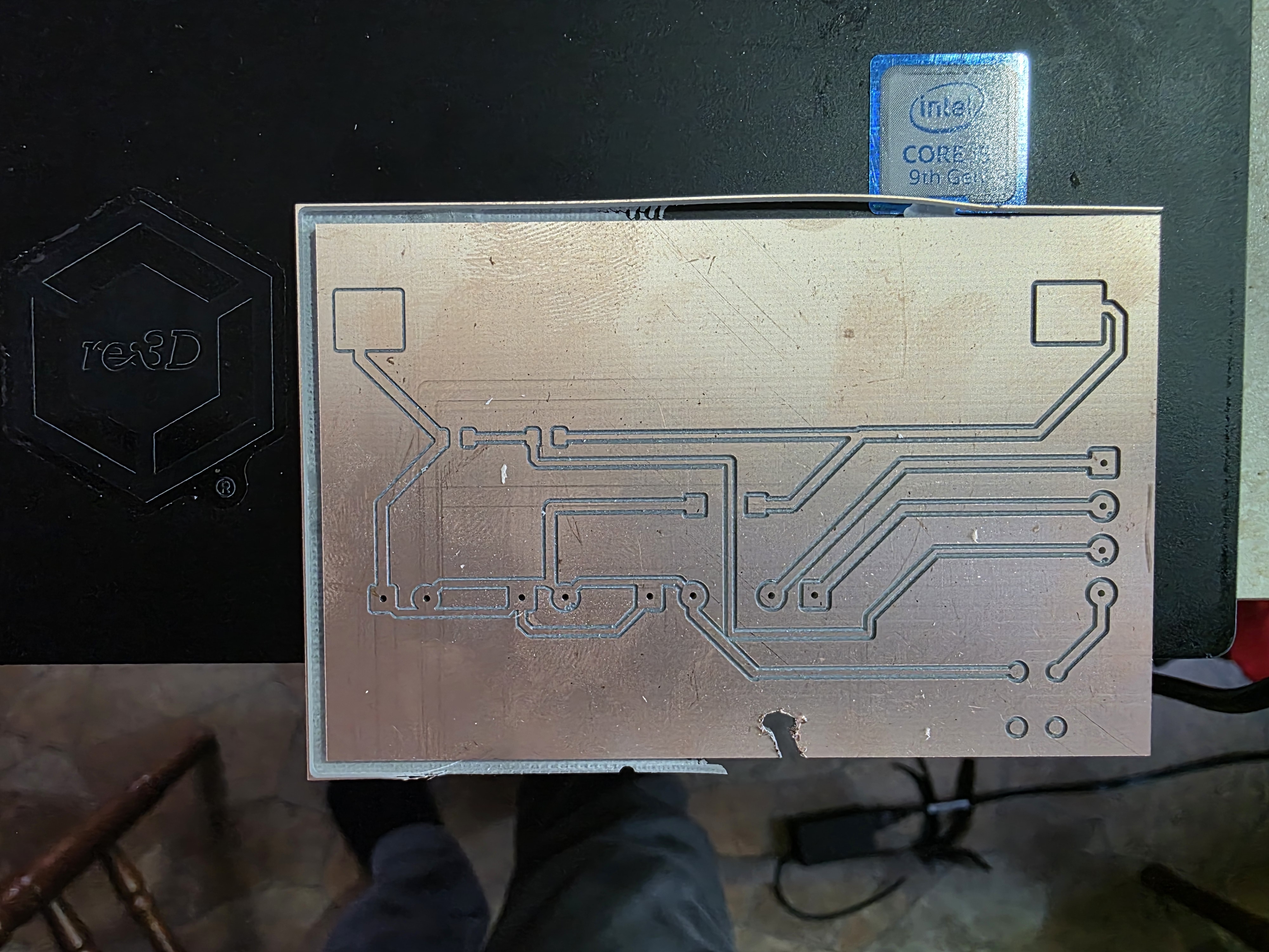
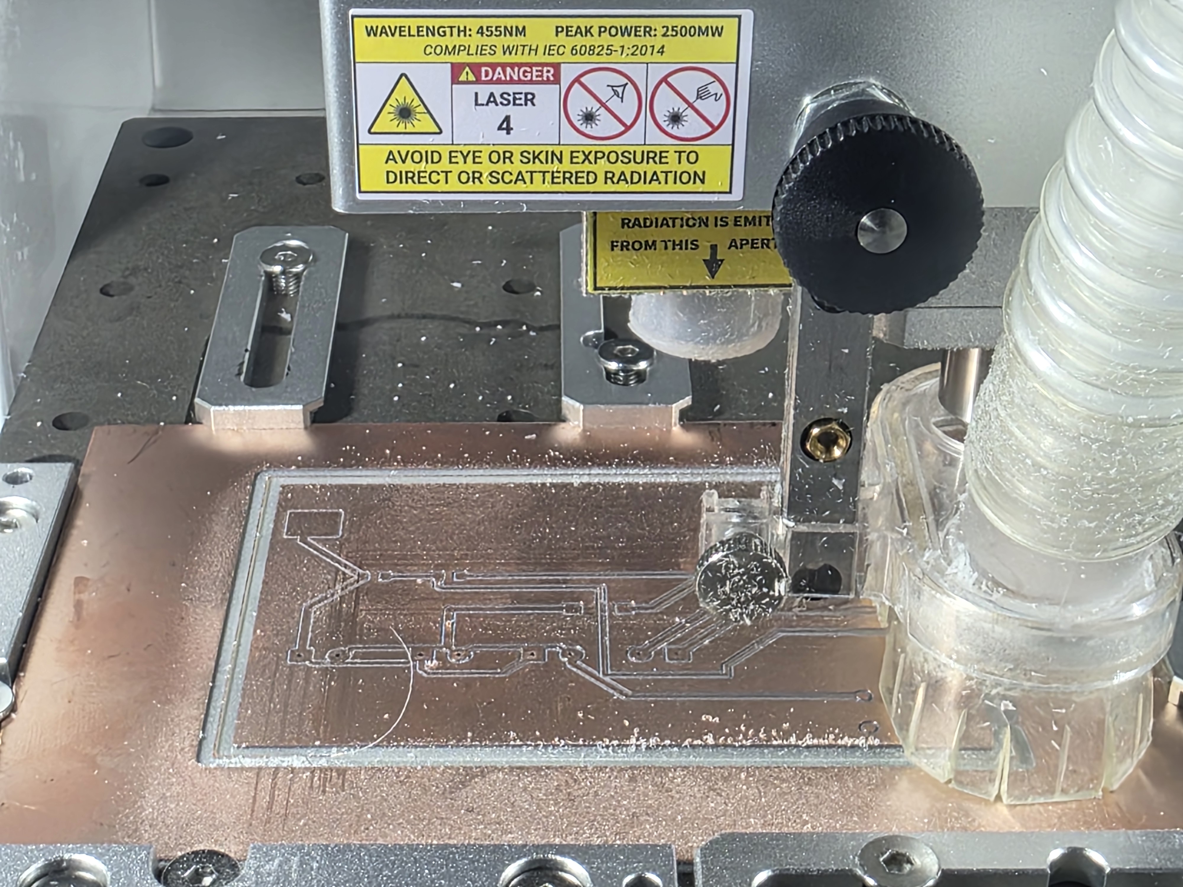
During the PCB milling process, I had a small problem where the board came loose while being milled. When the board shifted, the milling bit cut through part of the PCB and damaged some of the traces.
I also found that some of the traces were too close to the pads, which caused a few areas to become difficult to mill cleanly. Because of this, I had to go back and redesign parts of the PCB layout to improve the spacing and make the board easier to machine correctly.
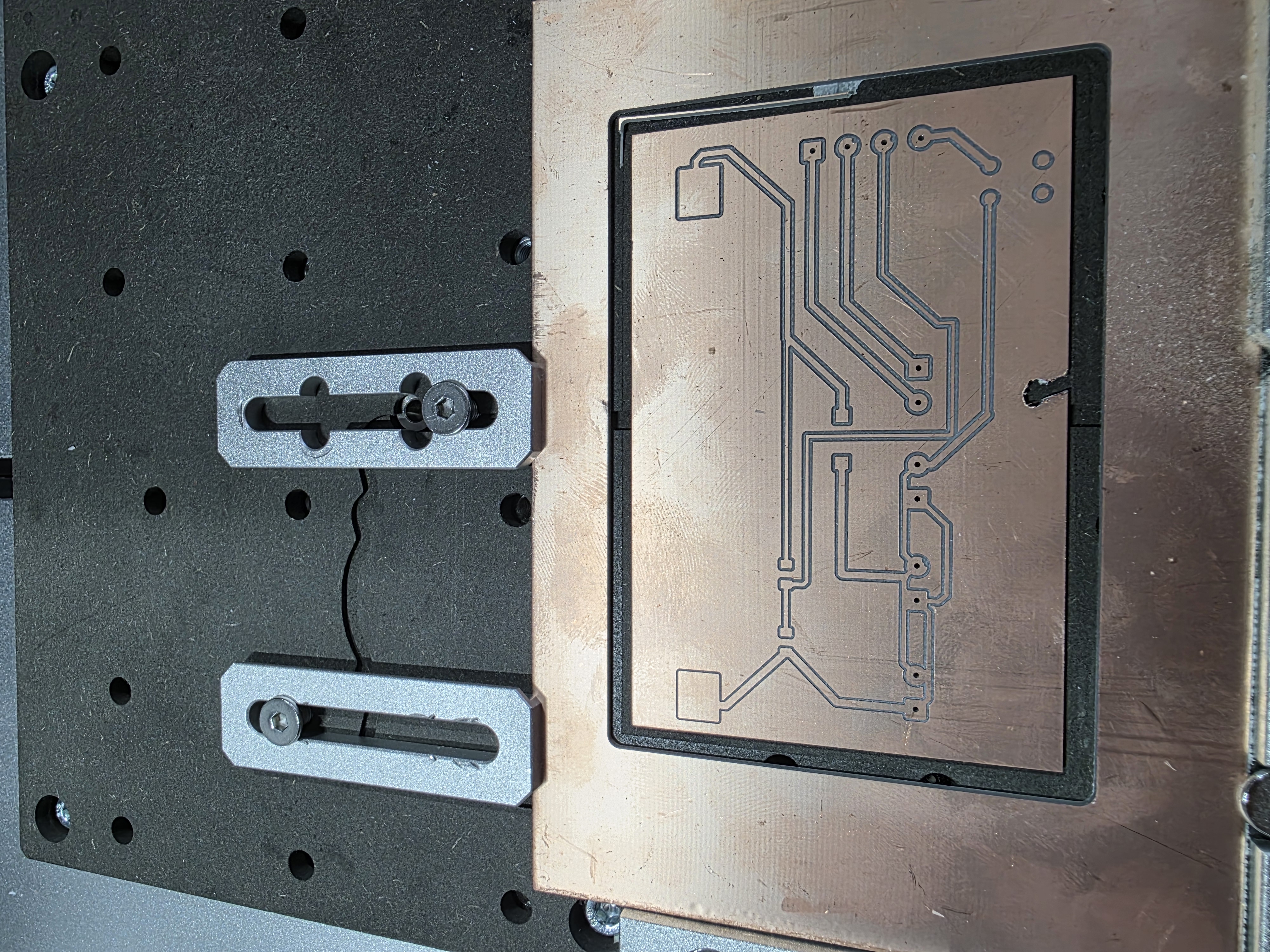
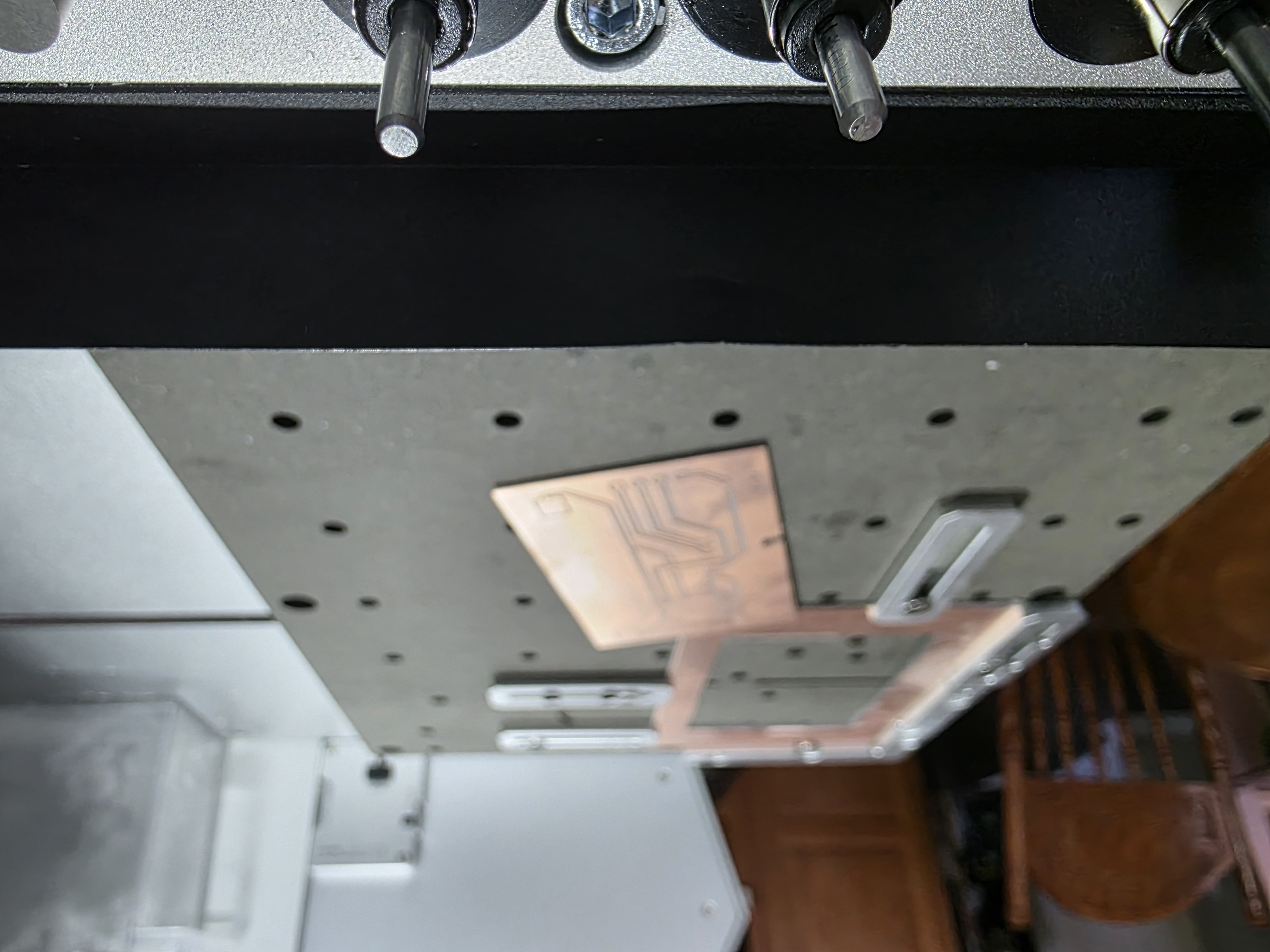
Even though the PCB had some problems during milling, the code and overall project logic still worked correctly. The redesign helped me understand how important trace spacing, board hold-down, and milling setup are during PCB production.
A new and improved PCB version will be coming soon as I continue improving the final project and preparing everything for final integration.
Help From Sparks
Sparks from ChatGPT helped me write, test, and fix the code for this project. Sparks helped me understand how to read battery voltage using two resistors, how to calculate the real battery voltage from the ESP32 analog reading, and how to use a button to switch between charger modes.
Sparks also helped me think through the PCB layout, trace spacing, CNC milling settings, and how to redesign the board after the first milling problems happened. This helped connect the coding side of the project with the electronics fabrication side of the project.
What I Learned
- I learned how to use an ESP32 as a user interface.
- I learned how to read battery voltage with an analog input.
- I learned why a voltage divider is needed to protect the ESP32.
- I learned how to use a button as an input device.
- I learned how to switch between different charger modes in code.
- I learned how important PCB trace spacing is during CNC milling.
- I learned how to redesign a PCB after machining problems.
- I learned how to connect my final project hardware to a working application.
Final Result
For Week 15, I created an application for my final project that connects the user to the battery checker and charger. The ESP32 reads the battery voltage, the screen shows the information, and the button switches between charging modes. I also began designing and milling a custom PCB for the project.
Even though the first PCB had some milling problems, the redesign process helped improve the overall project. This week was an important step toward turning the smart battery checker and charger into a complete working device with both hardware and software integration.