System Integration
Bringing the electronics, screen, charger modules, PCB, and enclosure together for my final project.
Final Project System Integration
For Week 16, the assignment was to design and document the system integration for my final project. My final project is a smart battery checker and charger. The goal is to combine the electronics, user interface, charging modules, custom PCB, voltage reading circuit, and enclosure into one complete system.
This week was focused on showing how all of the smaller parts connect together. Instead of only having separate tests on the bench, I started putting everything into one full device so it can work as a finished tool.
System Overview
- ESP32 touchscreen for the display and user interface
- Button input for switching between battery modes
- Voltage divider circuit for safely reading battery voltage
- Custom milled PCB for organizing the wiring and connections
- TP4056 Type-C charger module for single-cell 3.7V lithium batteries
- 2S charger module for 7.4V lithium battery packs
- Boost converter module for power testing and powering the electronics
- 3D printed enclosure to hold the screen, PCB, modules, and wiring
The battery connects through the battery input wires. The PCB sends the battery voltage through a voltage divider so the ESP32 can safely read it. The ESP32 then displays the voltage and battery mode on the screen.
Custom Milled PCB
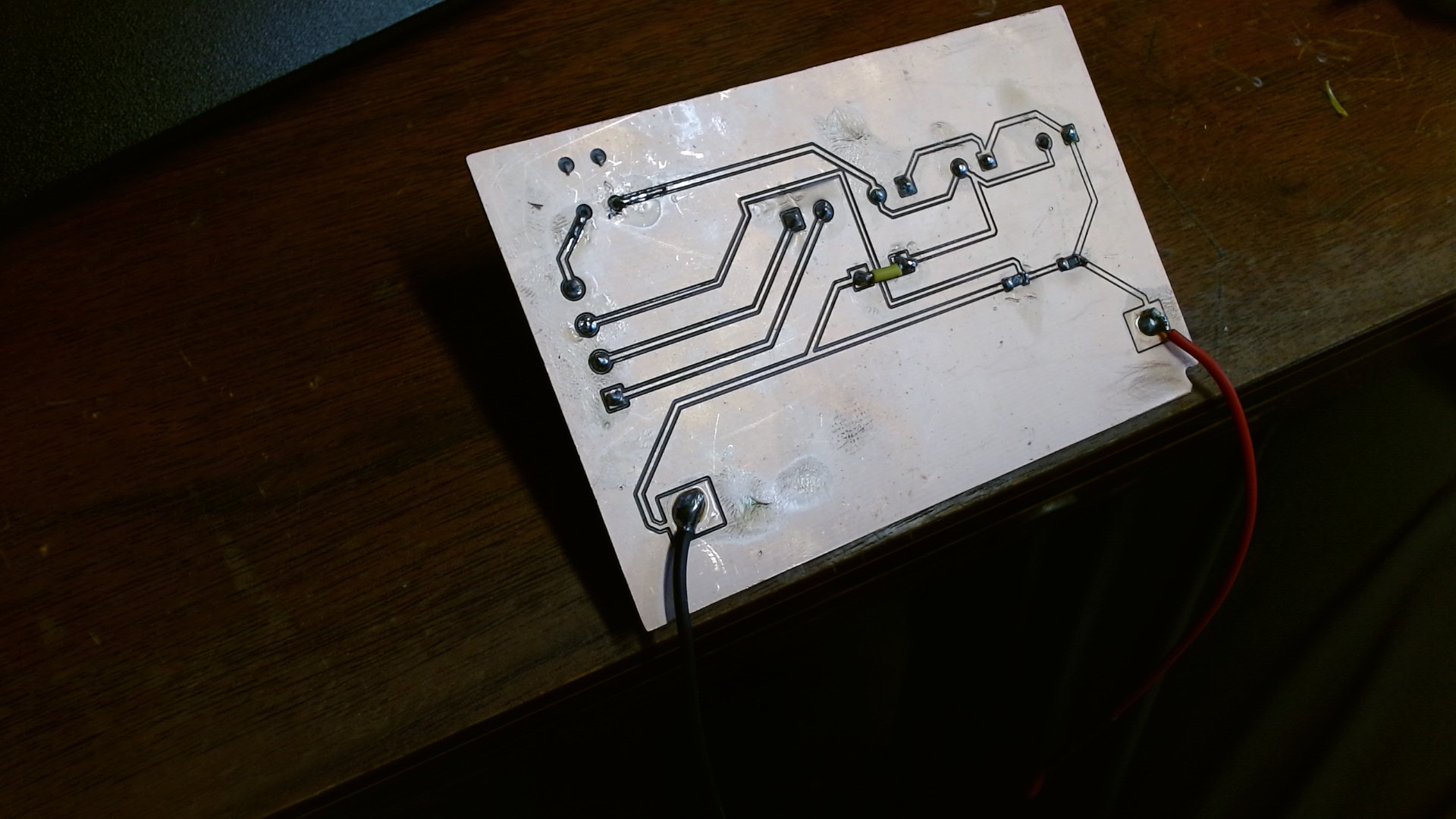
This is the custom PCB that I designed and milled for the final project. The PCB helps organize the wiring and makes the inside cleaner than having loose breadboard wires everywhere.
One important part of the PCB is the voltage divider. The voltage divider lets the ESP32 safely read battery voltage without sending too much voltage into the microcontroller pin.
Boost Converter
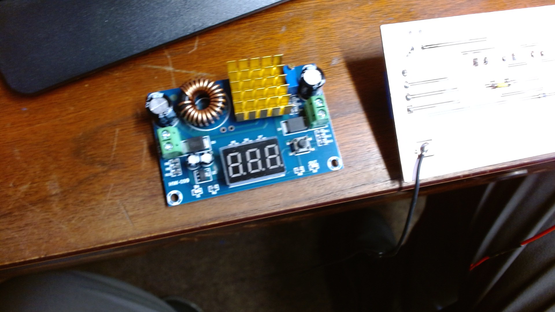
The boost converter helps step voltage up when needed so the system can power the screen and electronics correctly. Since the project works with batteries and charger modules, power management is one of the most important parts.
ESP32 Touch Screen
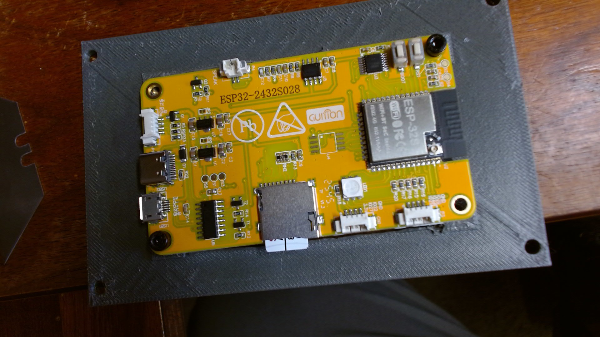
The ESP32 touchscreen is the main user interface. It displays the battery voltage, battery status, and selected mode. Instead of needing a computer or Serial Monitor, the user can see the information directly on the device.
Everything Connected Together
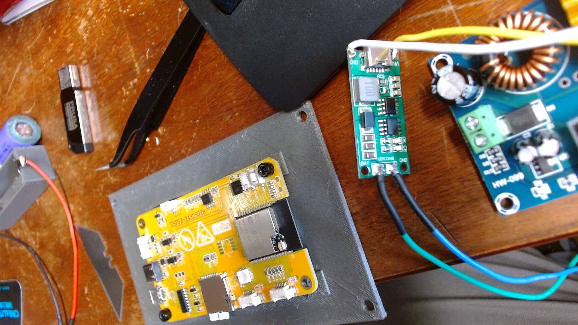
This picture shows the main parts of the system together. This is where the project started becoming one complete device instead of separate pieces. The PCB, boost converter, charger modules, wiring, and ESP32 screen all have to work together.
Single Battery Charger Module
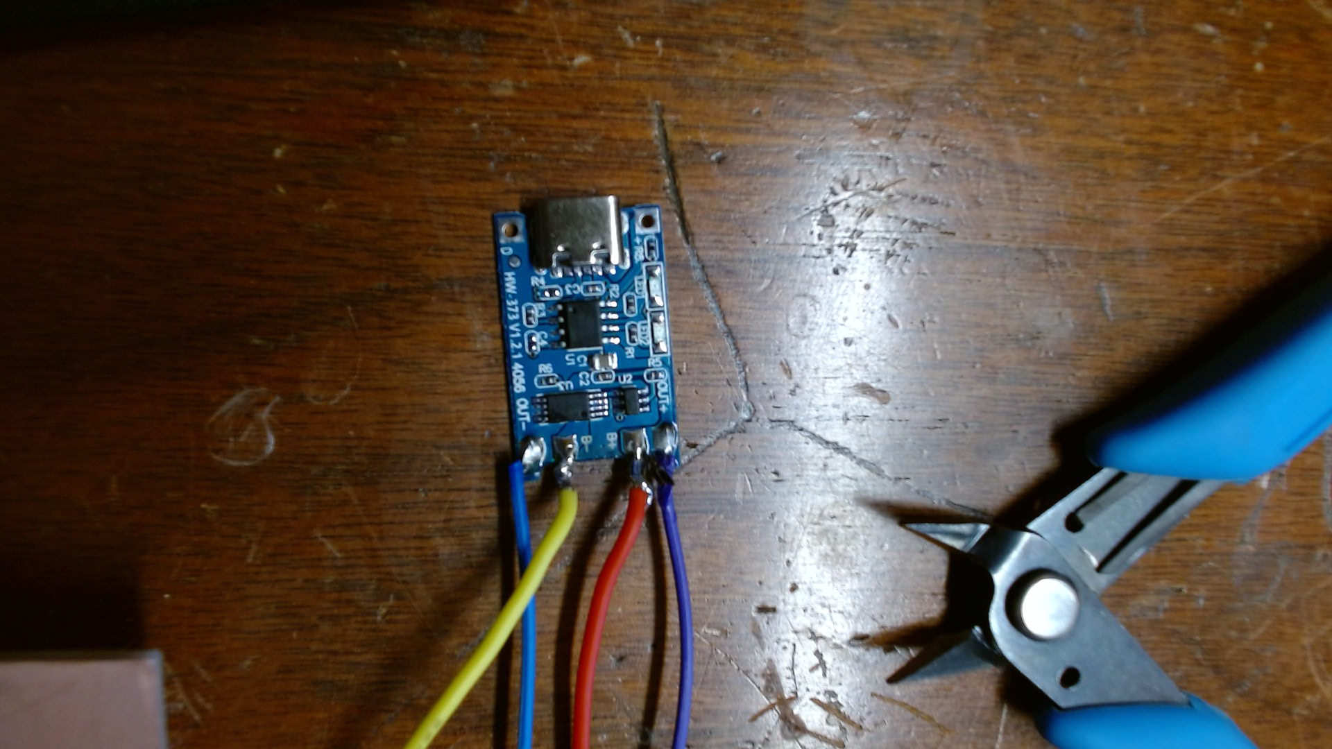
This is the single battery charger module used for charging a single 3.7V lithium battery. It has a USB Type-C input, which makes it easy to plug in power for charging.
How the System Works Together
The battery checking system uses the battery input, voltage divider on the PCB, and ESP32 screen. The charging system uses the charger modules and charging ports. The power system uses the boost converter to help provide the correct voltage.
The enclosure brings all of these parts together physically. The screen is mounted in the lid, the PCB and modules are mounted inside the box, and the charging ports line up with holes in the side of the enclosure.
Integration Problems and Fixes
During system integration, I had to think about how each part affected the other parts. One issue was making sure the charger modules stayed separate so power would not backfeed into the wrong part of the circuit.
I also learned that the PCB layout needs enough spacing around pads and traces so it can be milled cleanly on the CNC machine. Some of the first PCB areas were tight, so future versions need better spacing and cleaner routing.
What Worked
- The ESP32 screen powered on and displayed information.
- The PCB was milled and soldered.
- The voltage divider resistors tested correctly with a multimeter.
- The charger module and boost converter were connected into the system.
- The button and screen interface connected back to the final project idea.
- The project started working as one combined system instead of separate tests.
What Still Needs Improved
Some of the wiring and packaging still needs to be cleaned up. The enclosure holes may need small adjustments so the charger ports and screen fit better. The PCB design may also need more spacing around some pads and traces.
What I Learned
- I learned how to combine separate project parts into one system.
- I learned why power management is important when using batteries.
- I learned why charger modules need to be isolated from each other.
- I learned how the PCB helps organize the final wiring.
- I learned how the enclosure affects the electronics layout.
- I learned that system integration is not just wiring parts together, but making sure everything works safely as one device.