Final Project
A smart battery checker and charger with an ESP32 touchscreen, custom PCB, charging modules, and integrated enclosure.
Final Presentation
Here is my Google Doc for my SparkIon final presentation. This document includes the links to my final presentation slide and project video.
📊 View SparkIon Final Presentation Slide and Video
My final project is a smart battery checker and charger system designed to safely read battery voltage, display information on an ESP32 touchscreen, and charge lithium batteries using USB Type-C charging modules.
This project combines electronics design, PCB milling, embedded programming, 3D printing, system integration, fabrication, and troubleshooting into one complete device.
What Does It Do?
The system reads battery voltage through a voltage divider circuit and displays the information on the ESP32 touchscreen. A push button allows the user to switch between different display modes and system functions.
The project supports both single-cell lithium batteries and larger battery packs using separate charging systems and boost converter modules.
Project Overview Video
This video shows the completed project operating and switching between display modes.
PCB Milling Video
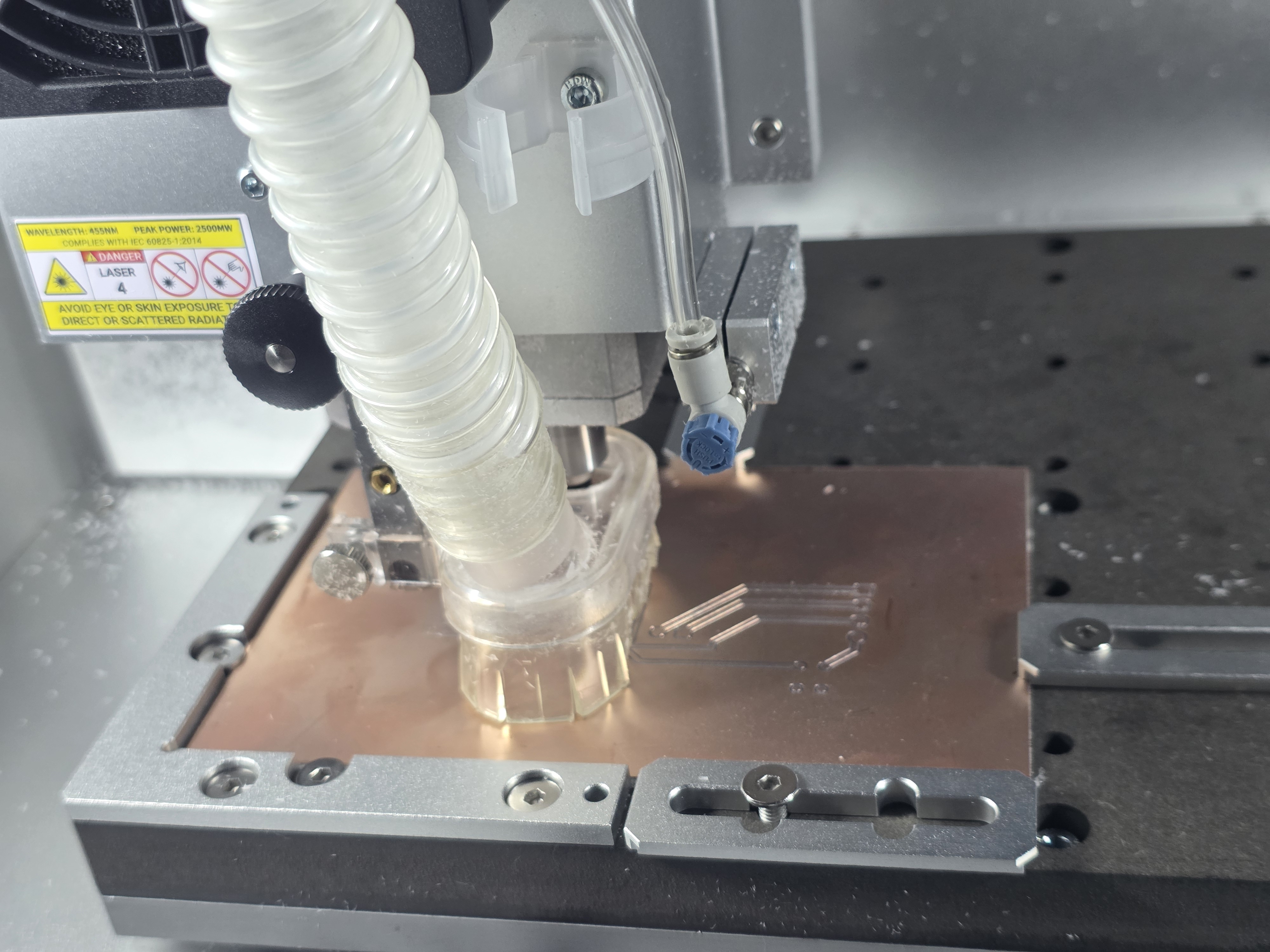
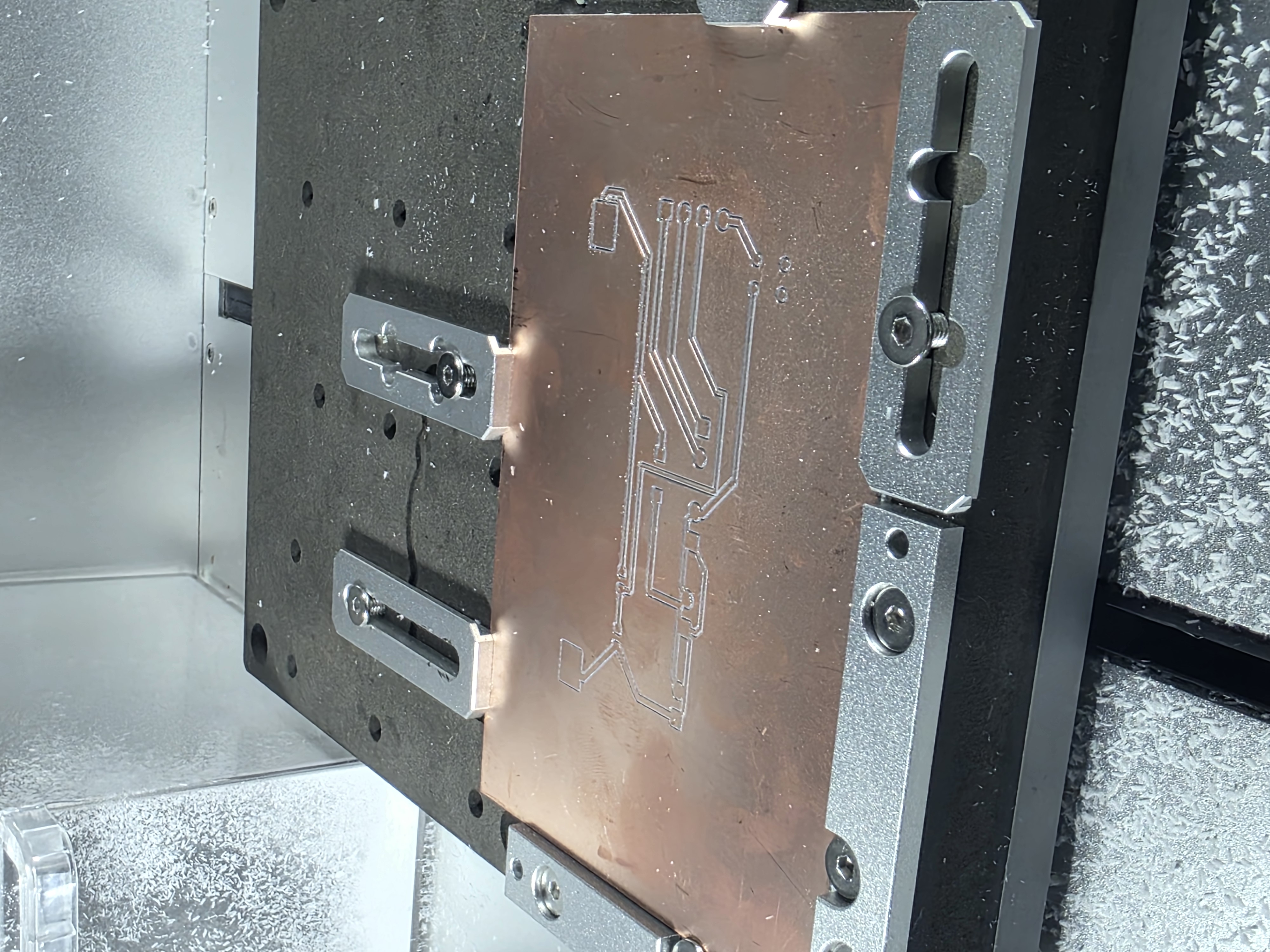
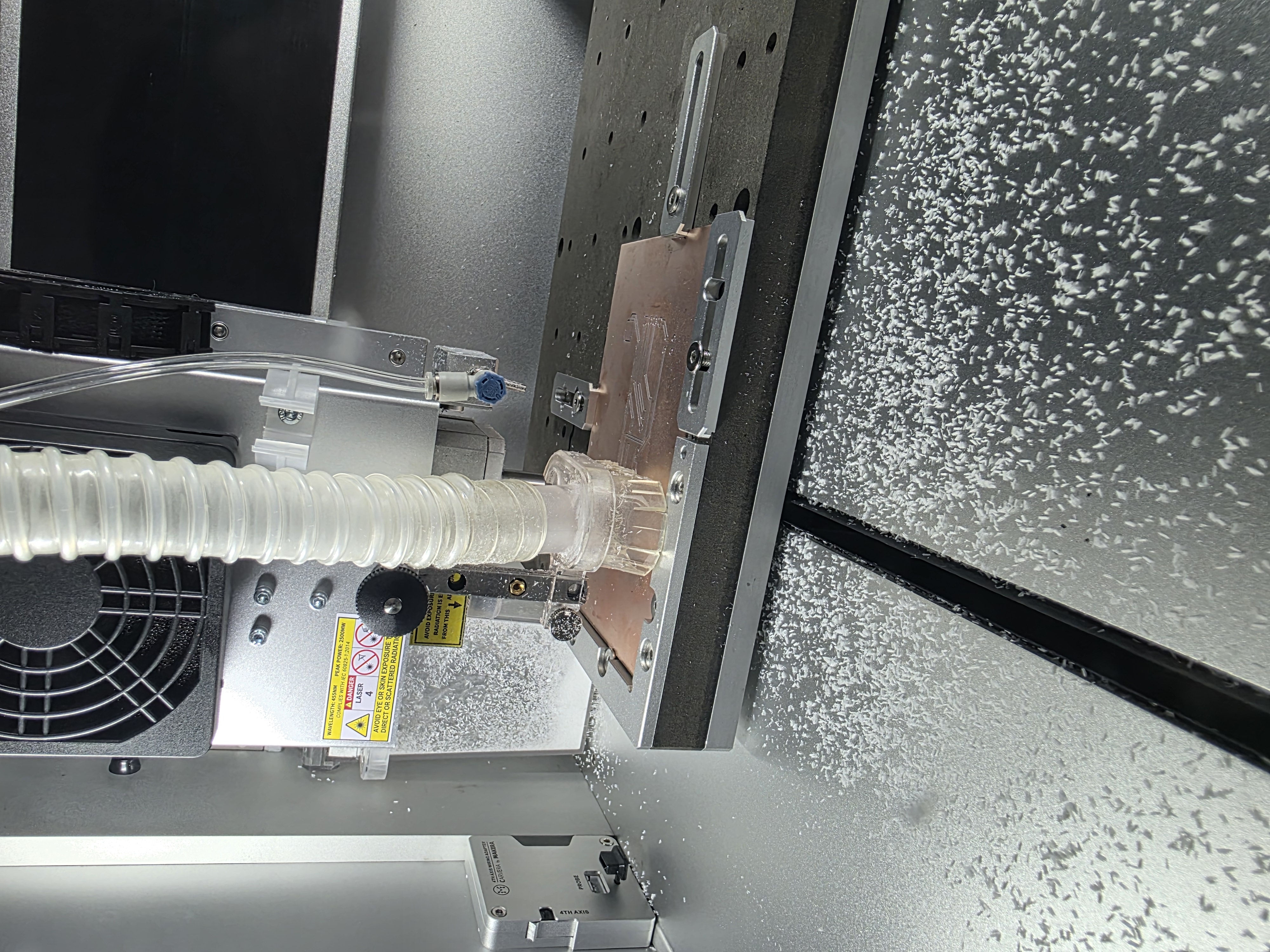
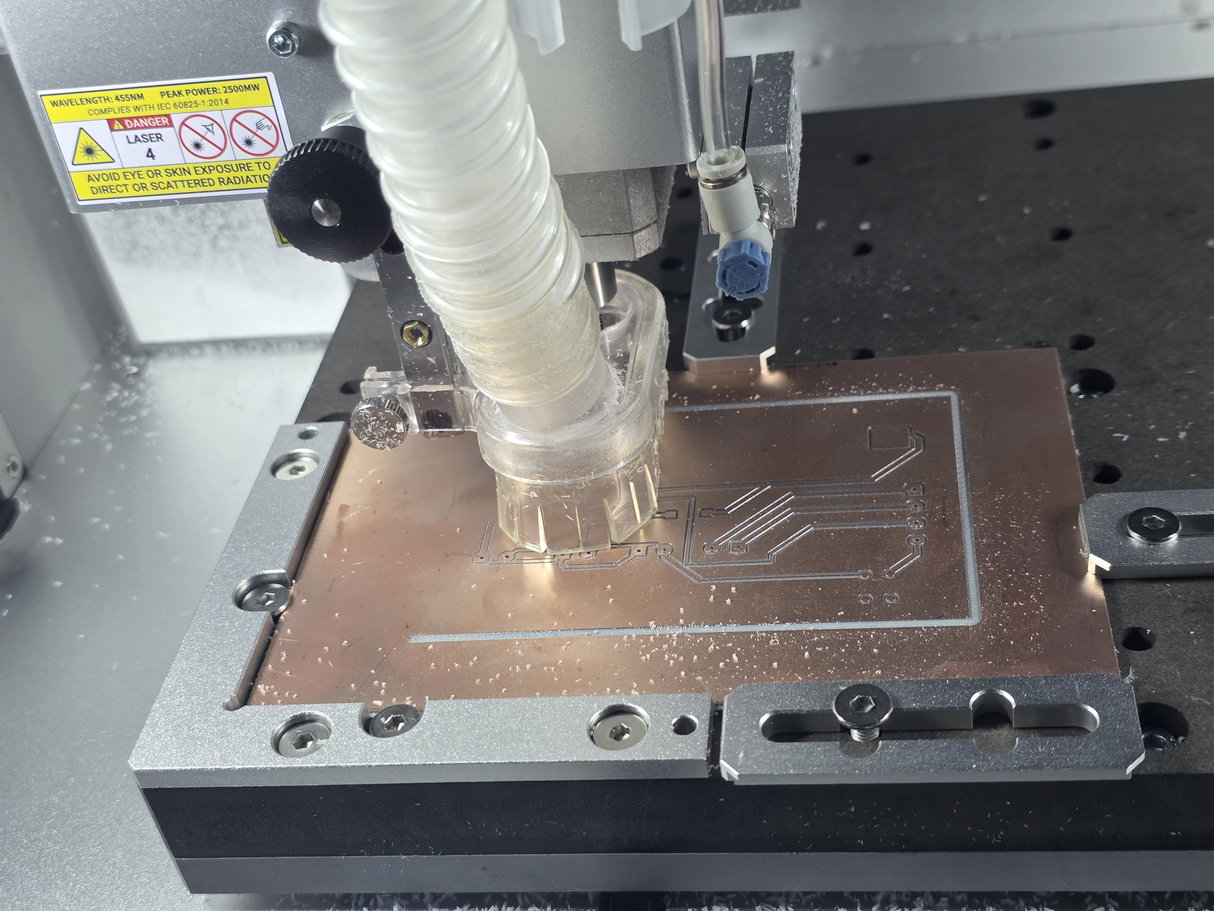
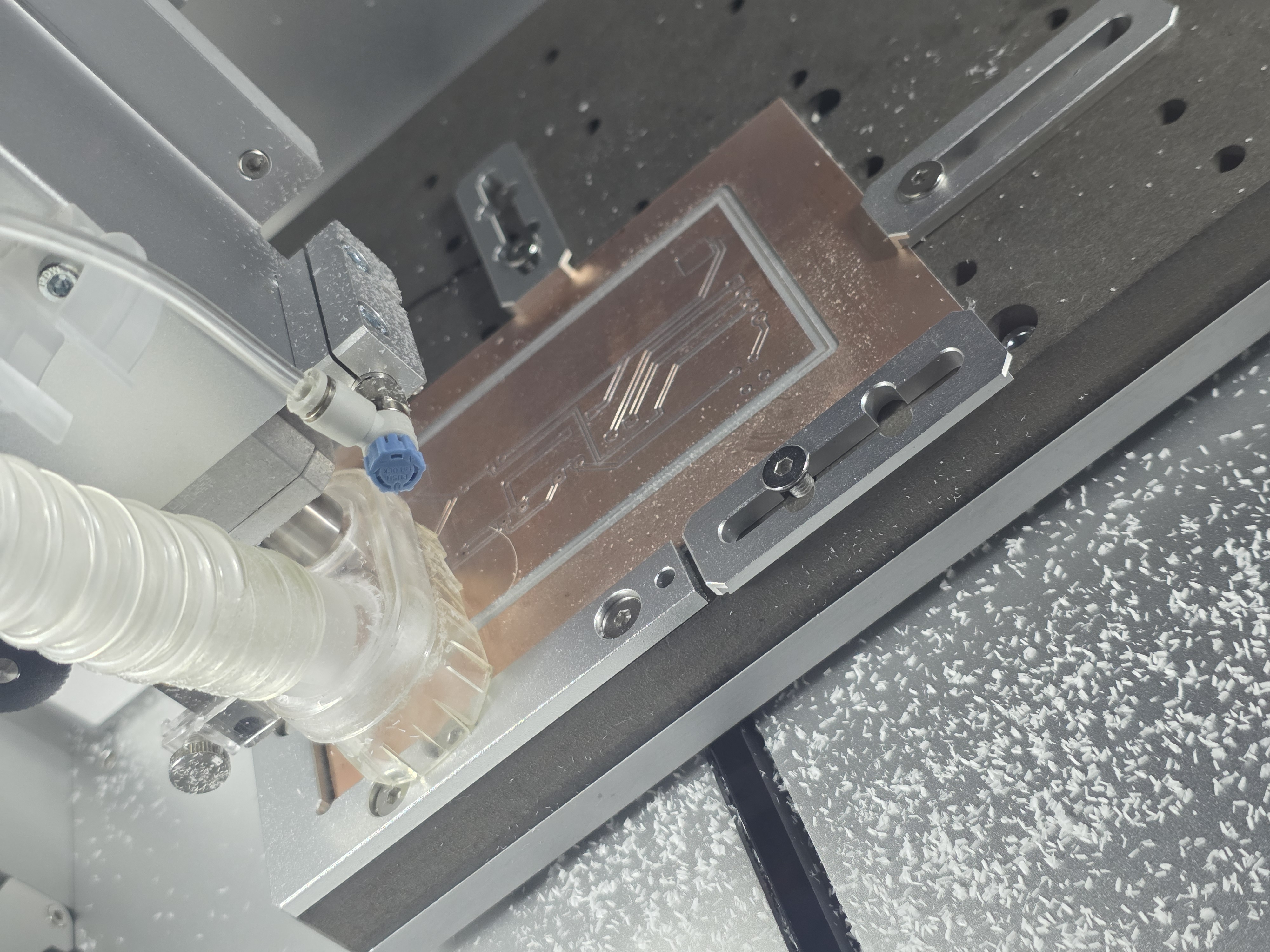
This video shows the CNC milling process used to create the custom PCB.
What I Designed
- Custom PCB
- Battery voltage divider circuit
- ESP32 touchscreen interface
- Charging and battery monitoring system
- Custom enclosure and packaging
- Integrated wiring layout
Materials and Components
- ESP32 touchscreen
- Custom milled PCB
- Voltage divider resistors
- USB Type-C charger modules
- Boost converter module
- Push button
- Battery connectors
- 3D printed enclosure
- Wires and solder
PCB Milling and Electronics
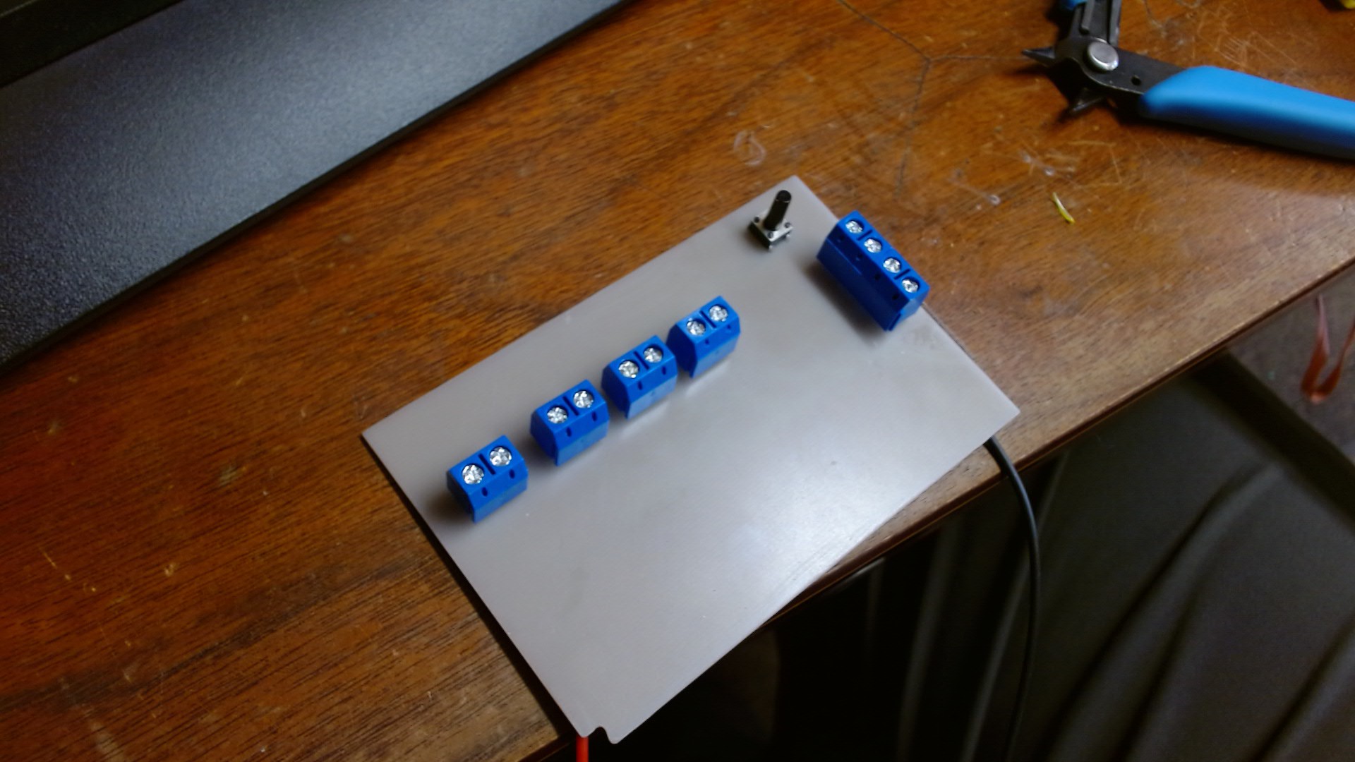
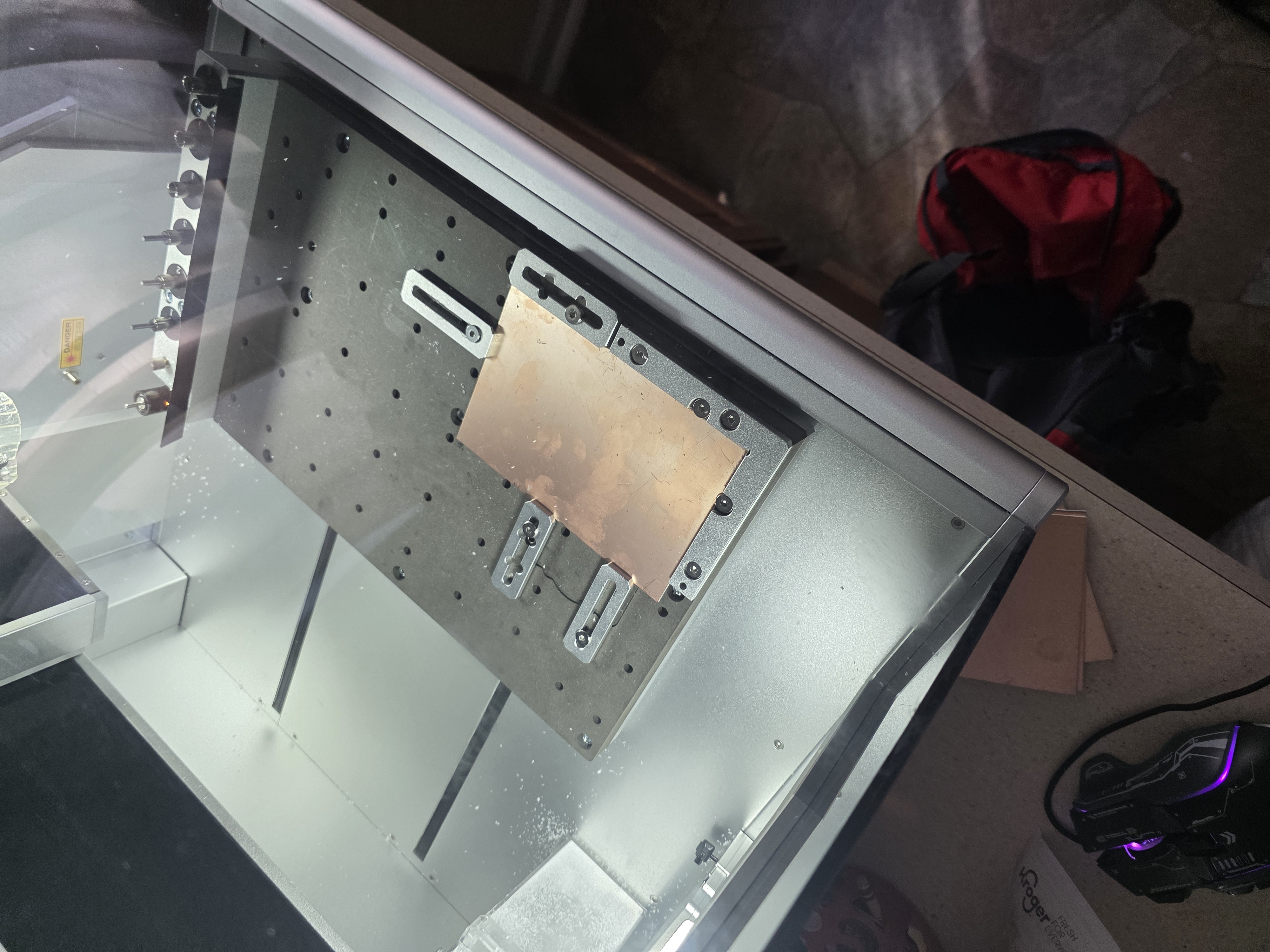
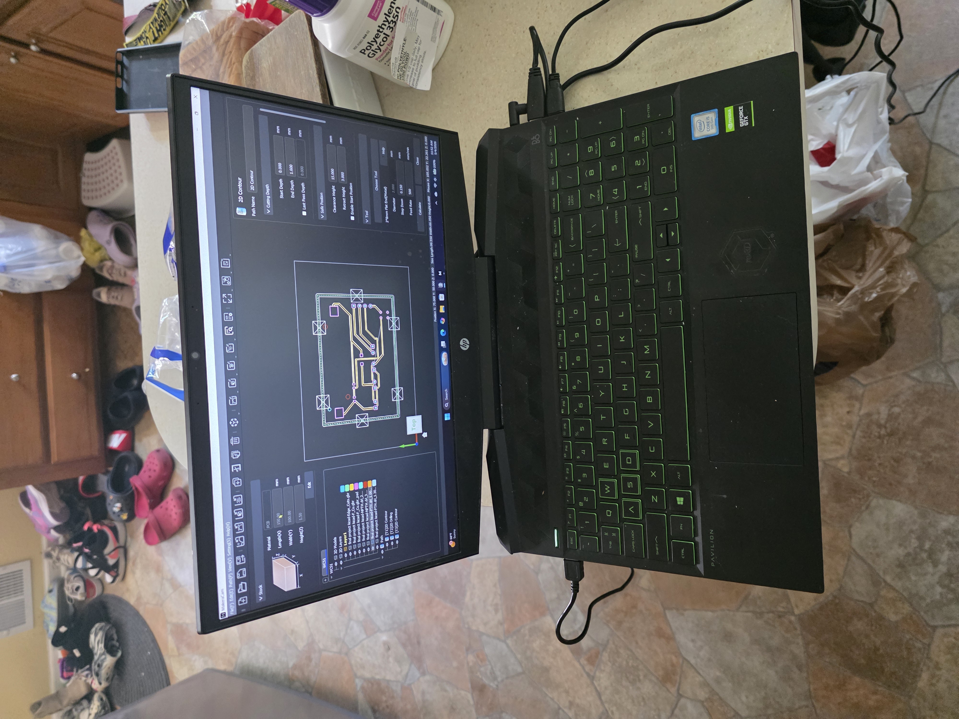
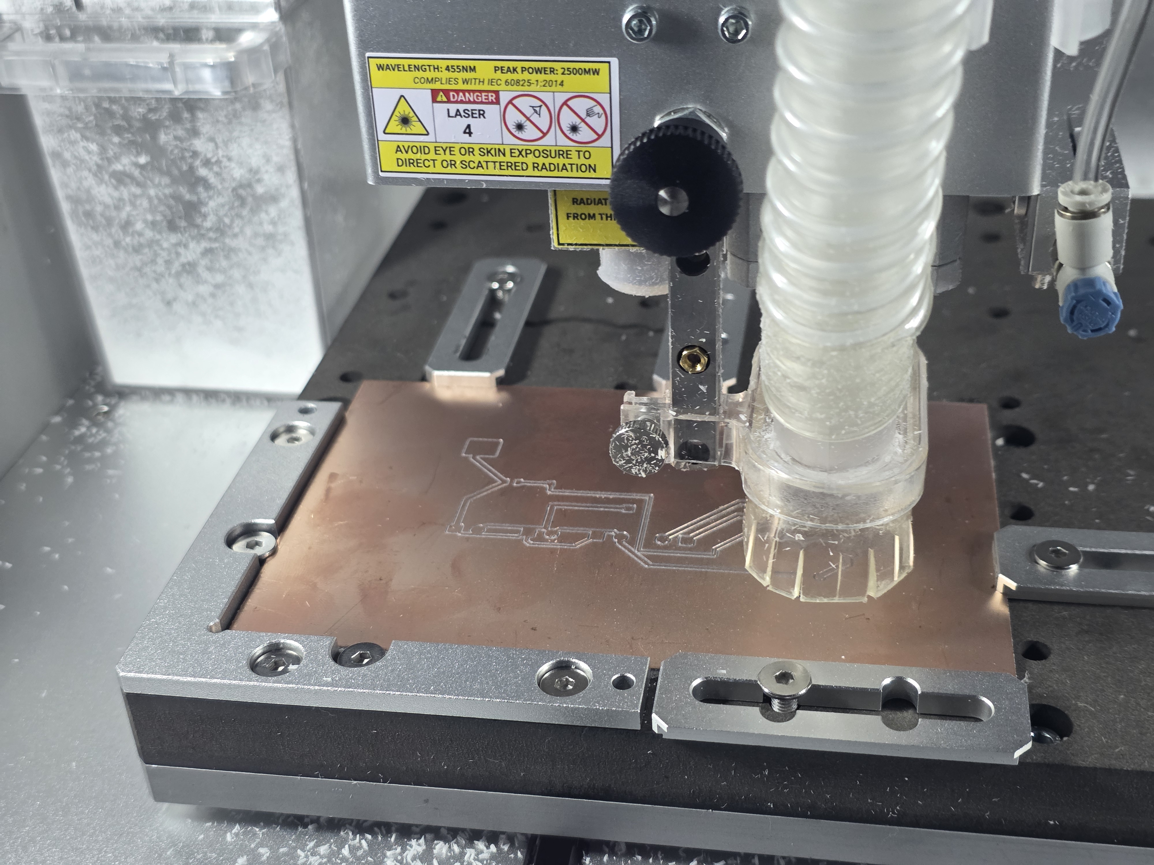
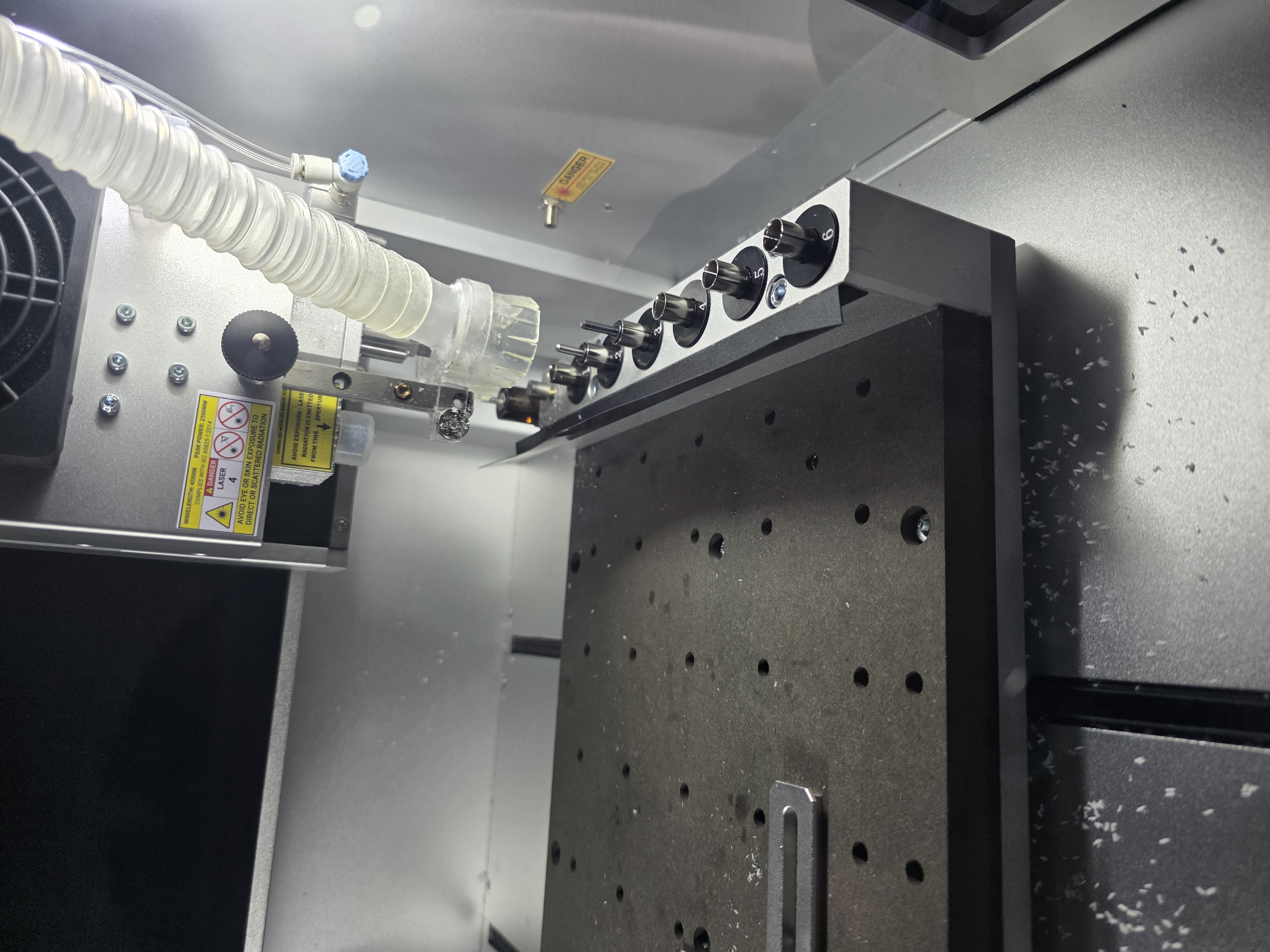
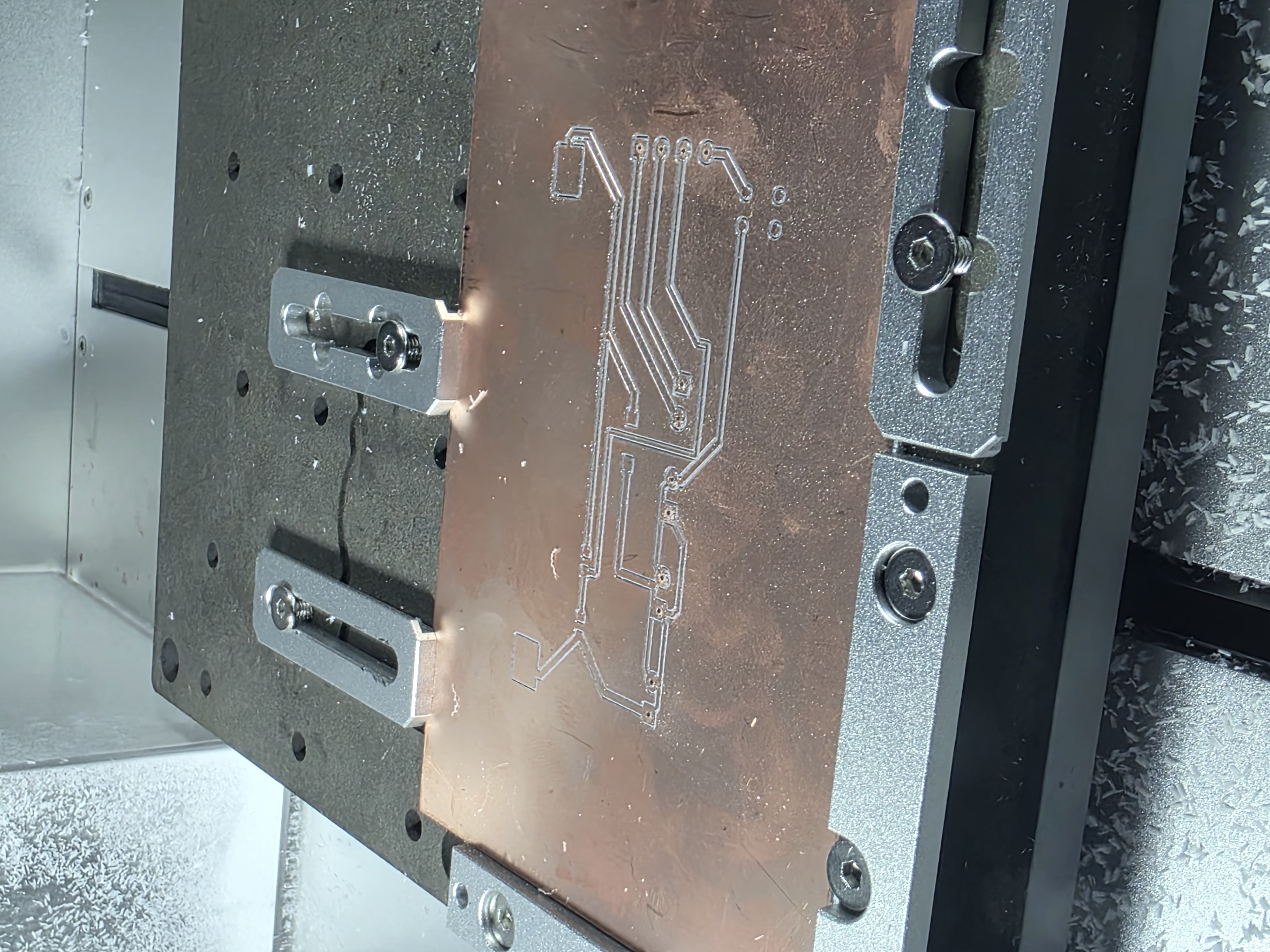
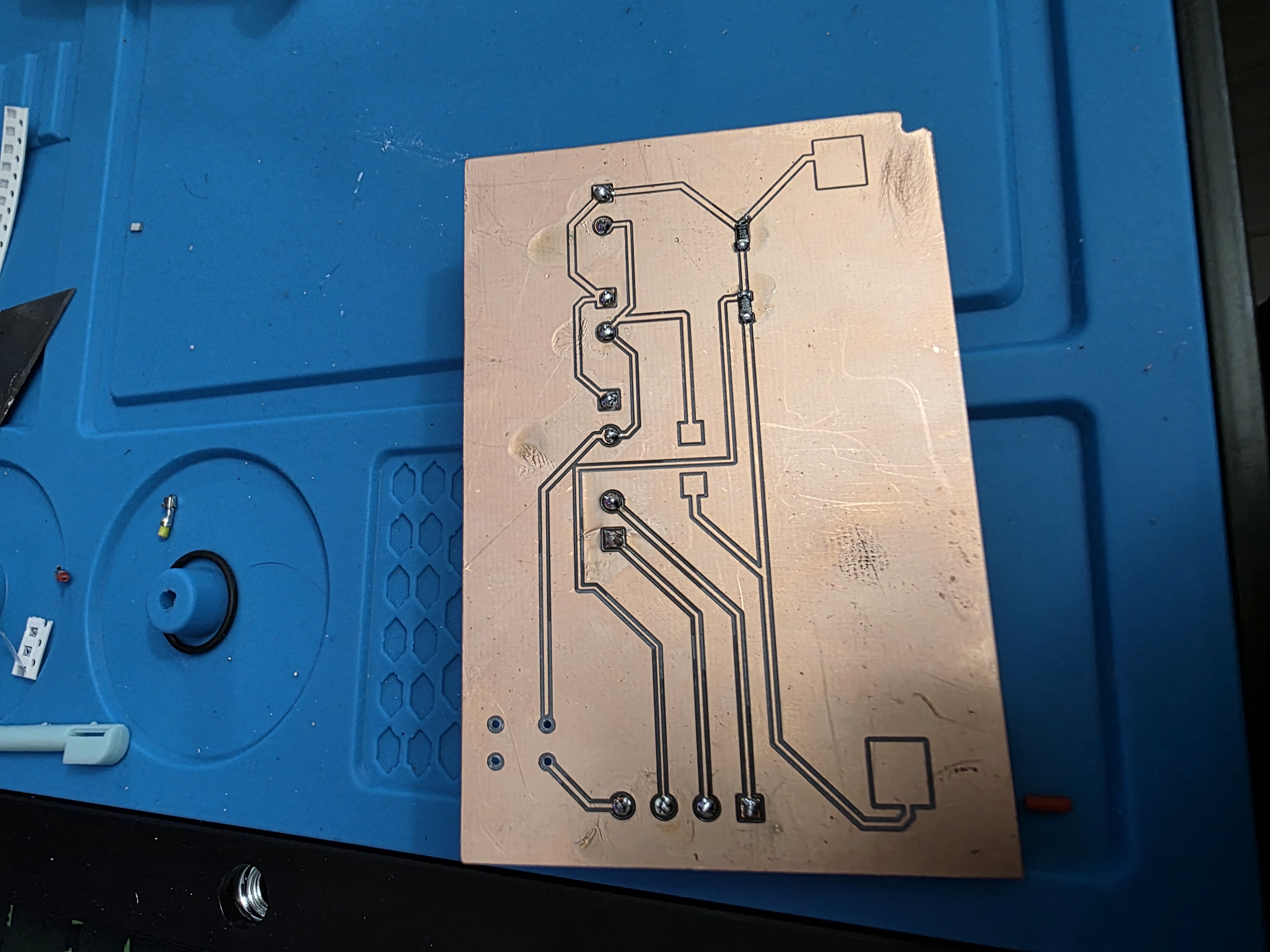
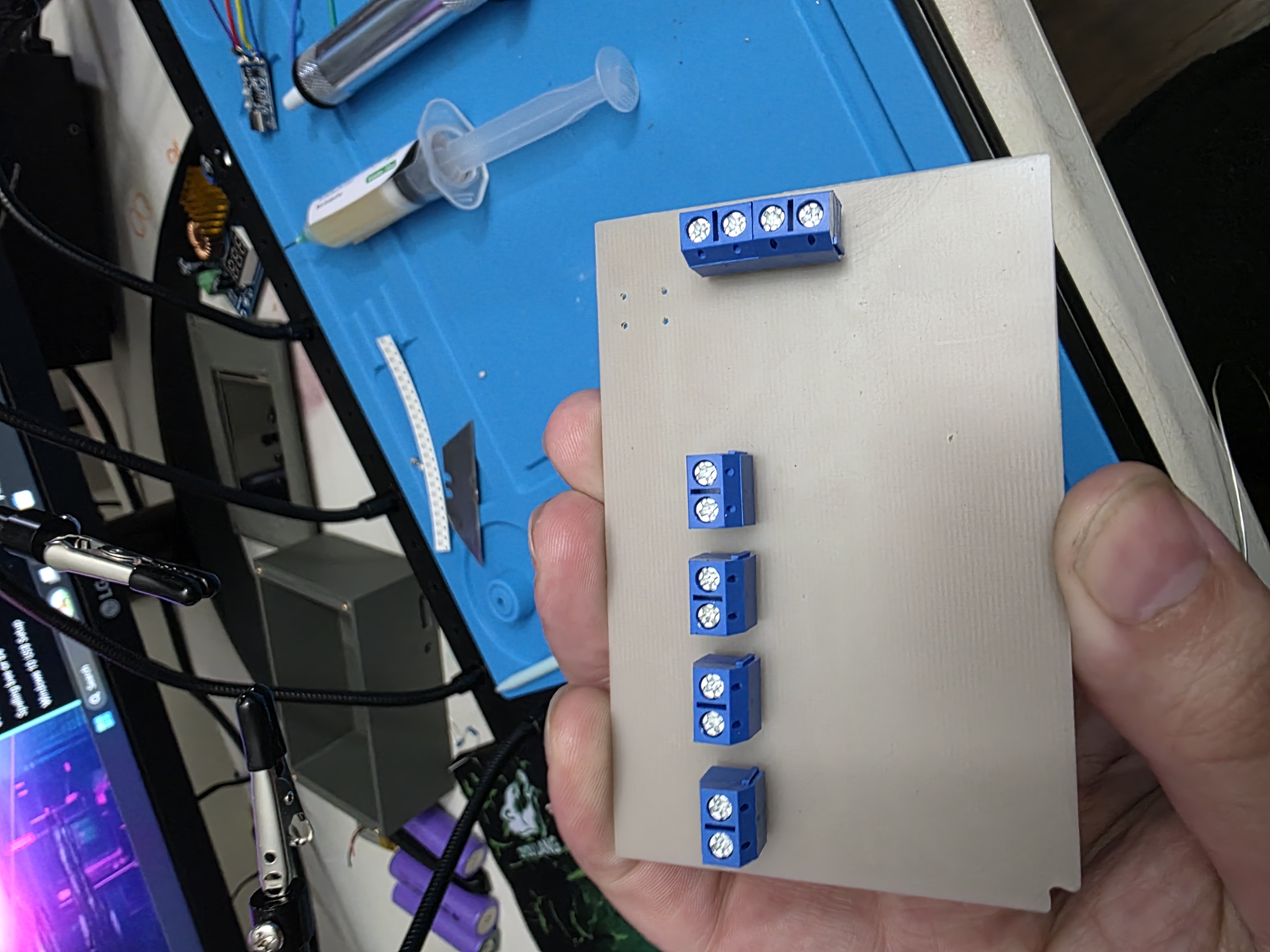
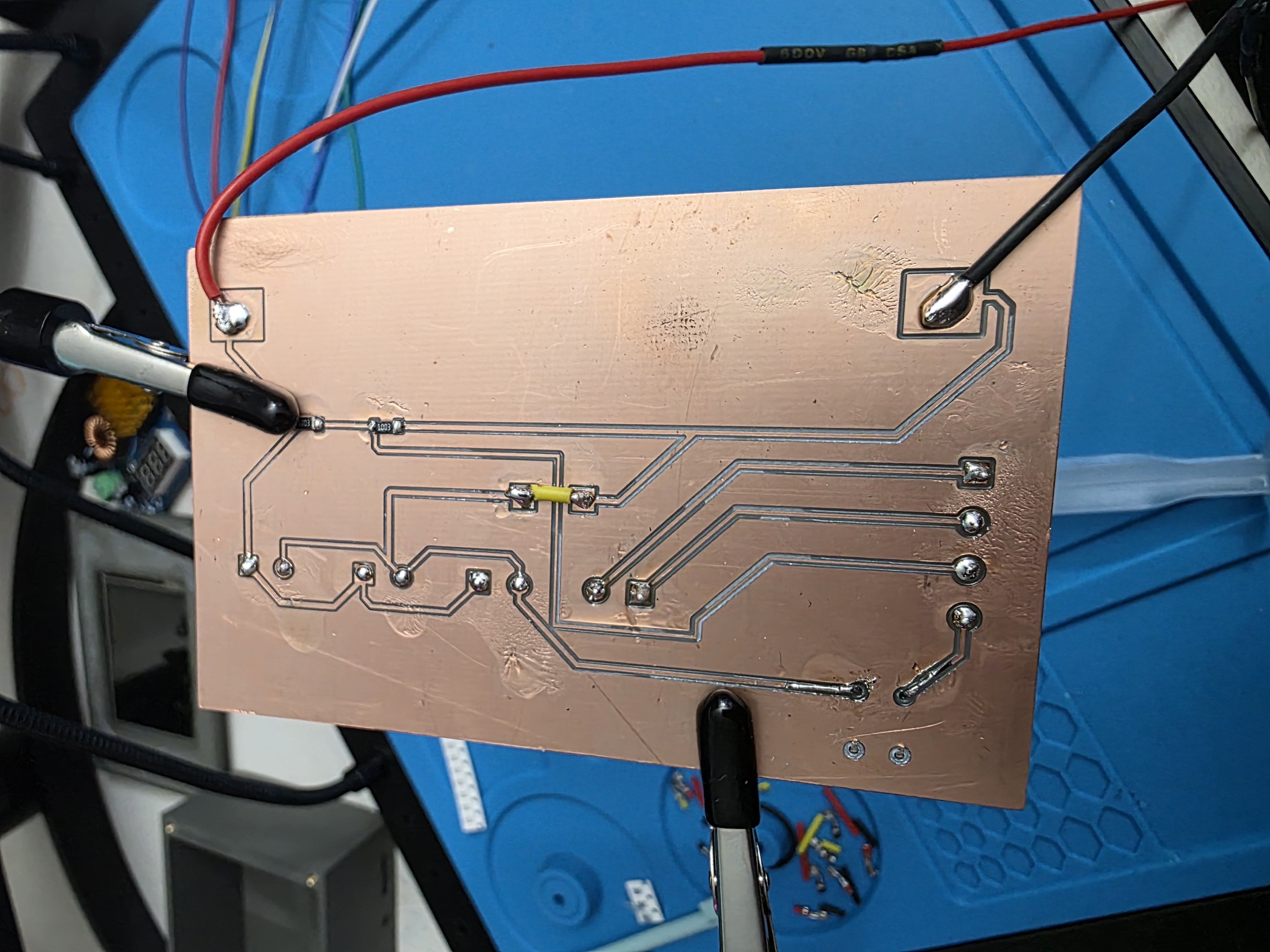
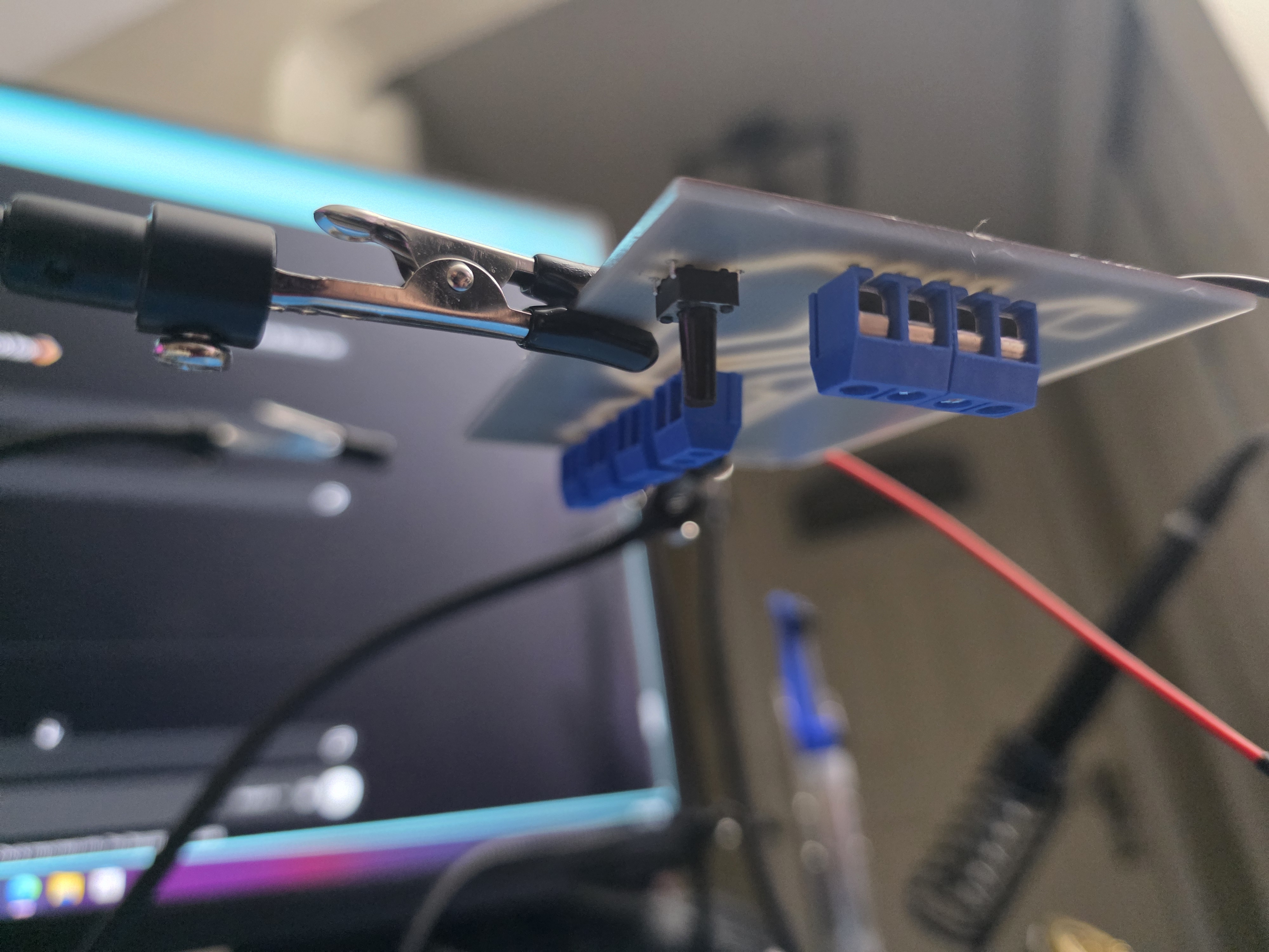
The PCB was designed and milled using the Makera Carvera CNC machine. During development I had to redesign traces and spacing multiple times to improve milling results and soldering reliability.
System Integration
The project combines multiple systems together into one device: the ESP32 touchscreen, charging modules, boost converter, voltage divider, custom PCB, and enclosure.
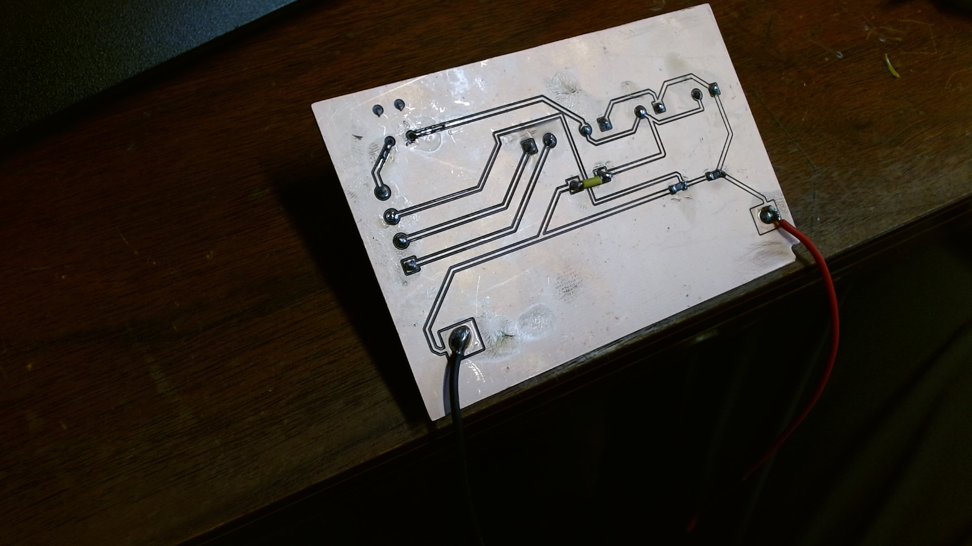
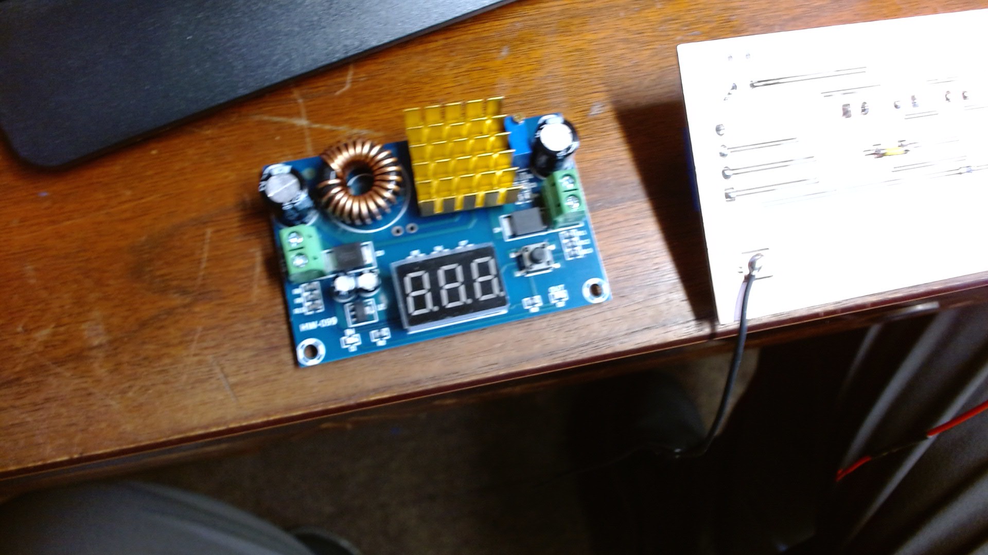
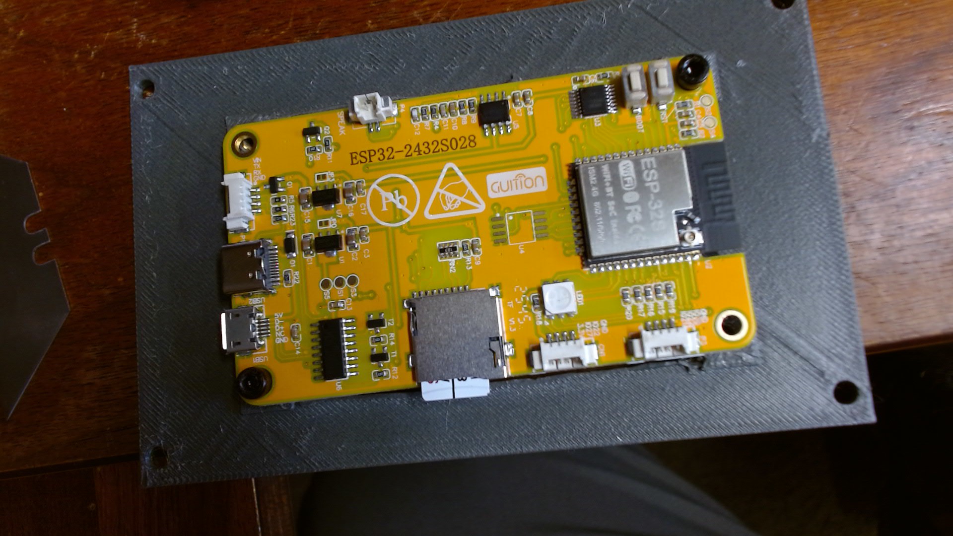
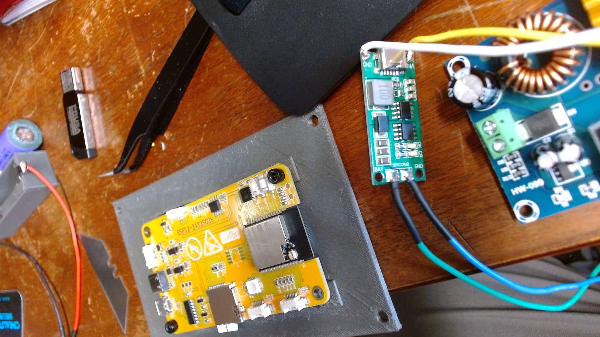
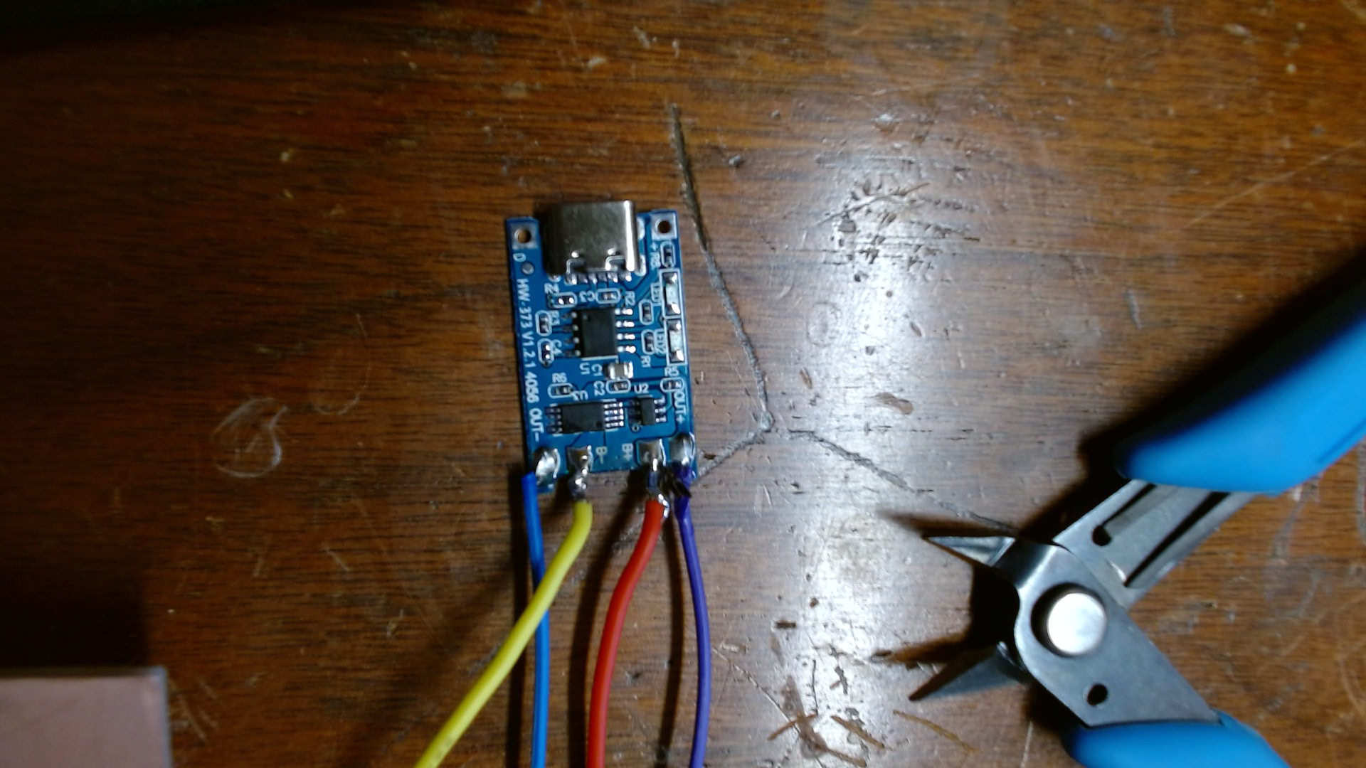
The ESP32 works as the user interface while the custom PCB handles the voltage reading system and module connections.
Programming and Assembly
The ESP32 was programmed using Arduino IDE and TFT_eSPI libraries. The code reads battery voltage values and displays the information on the screen.
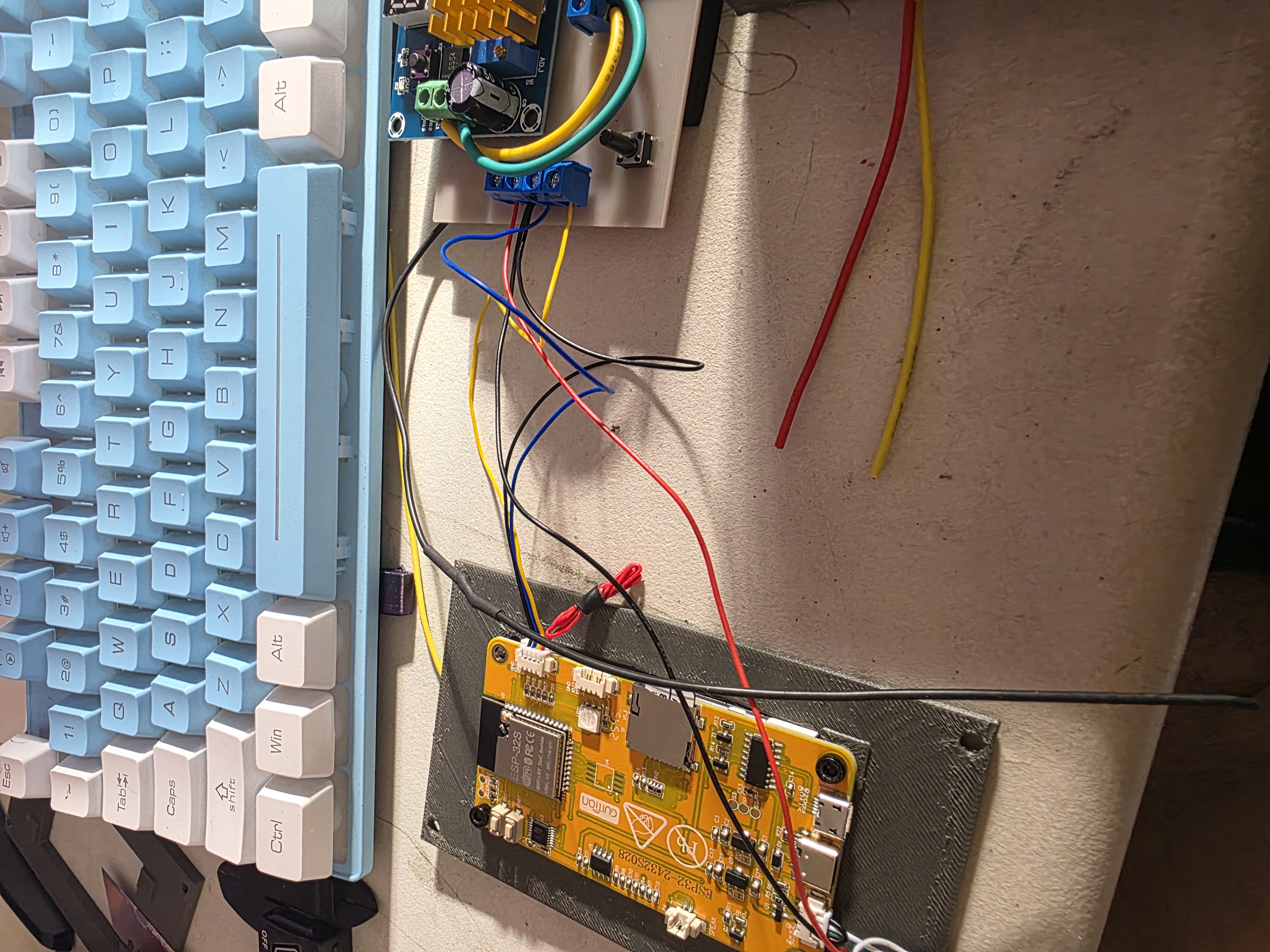
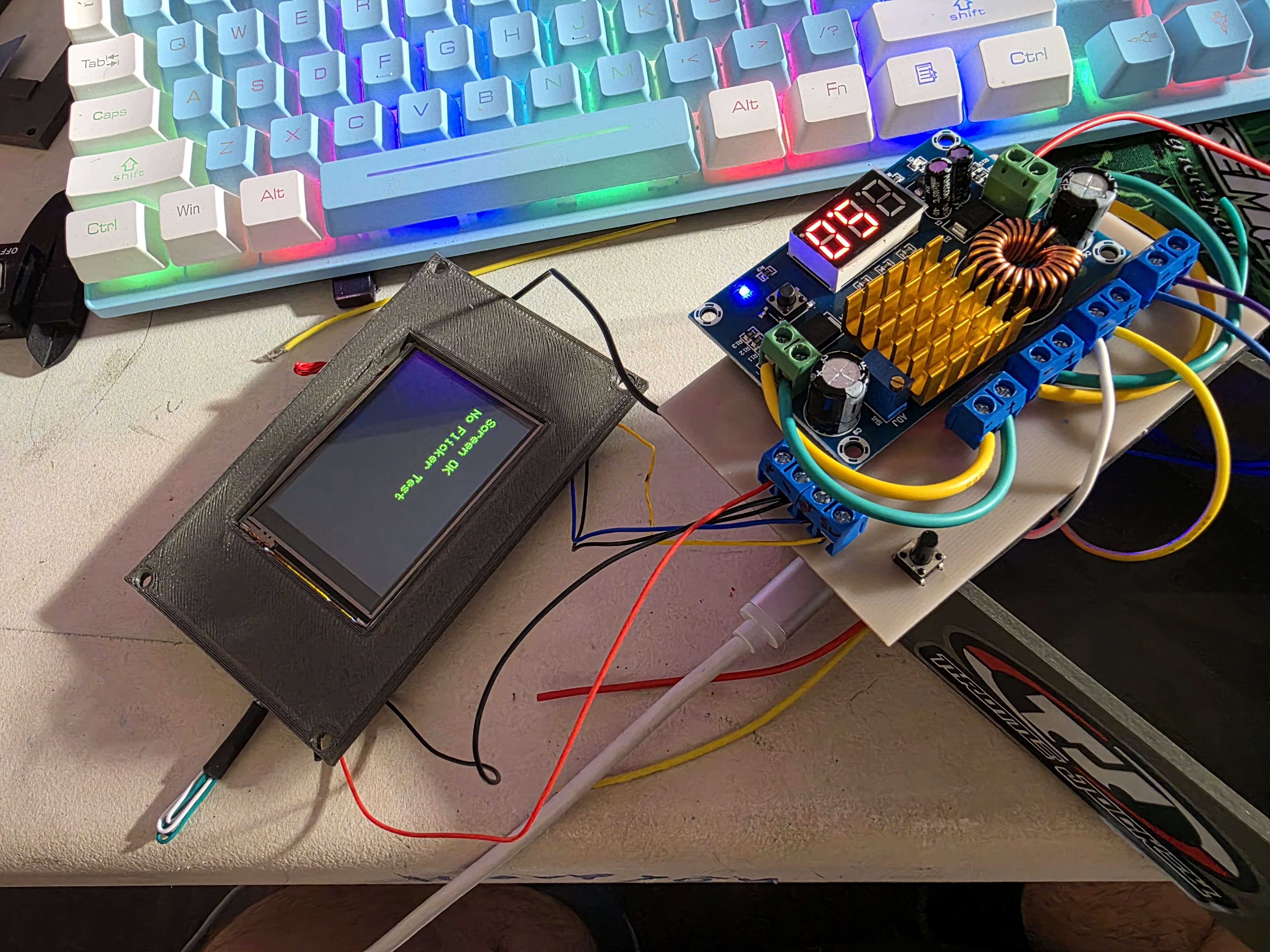
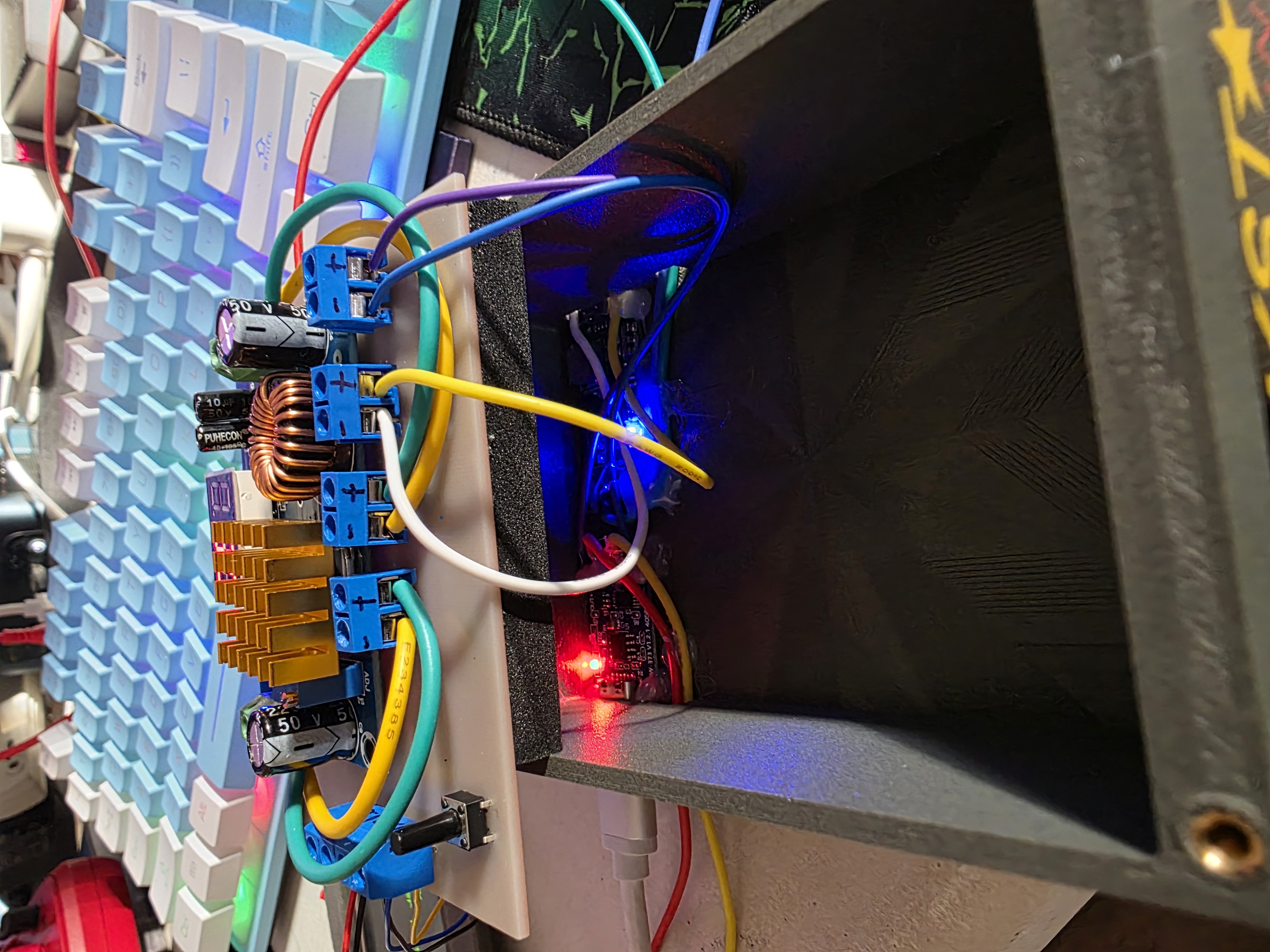
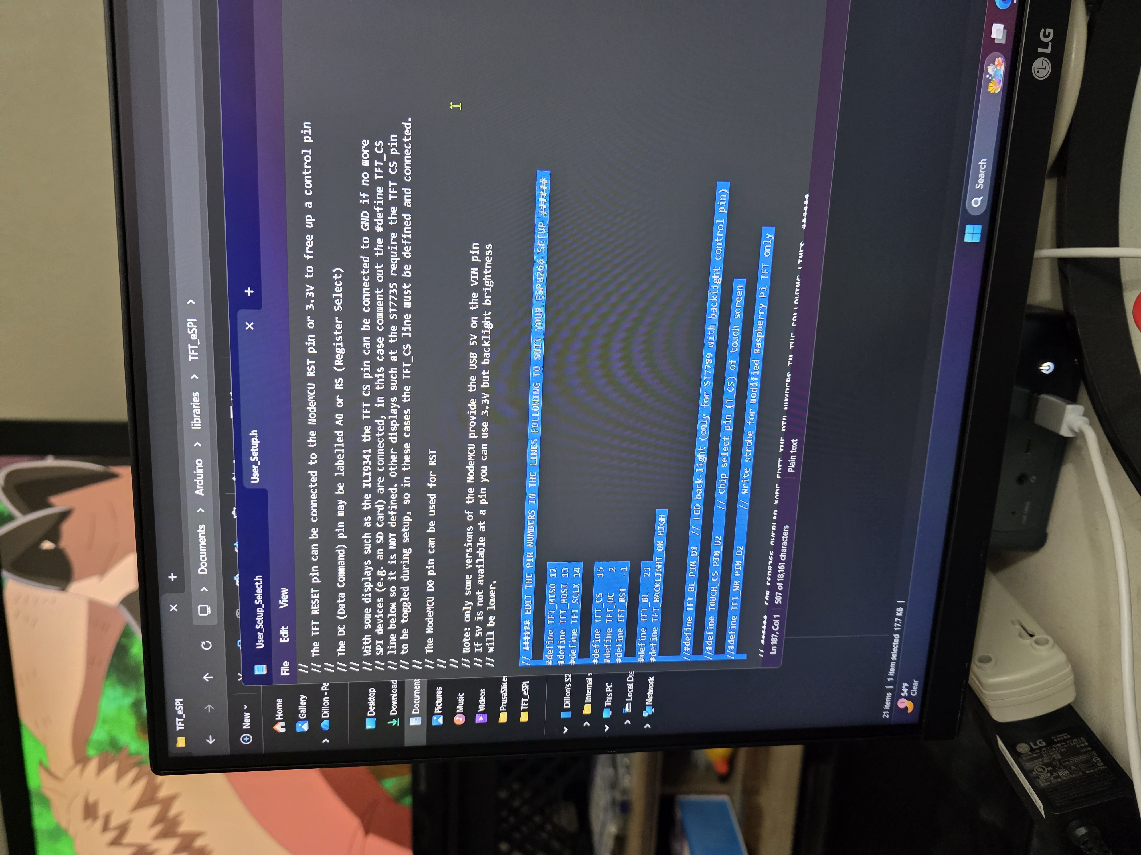
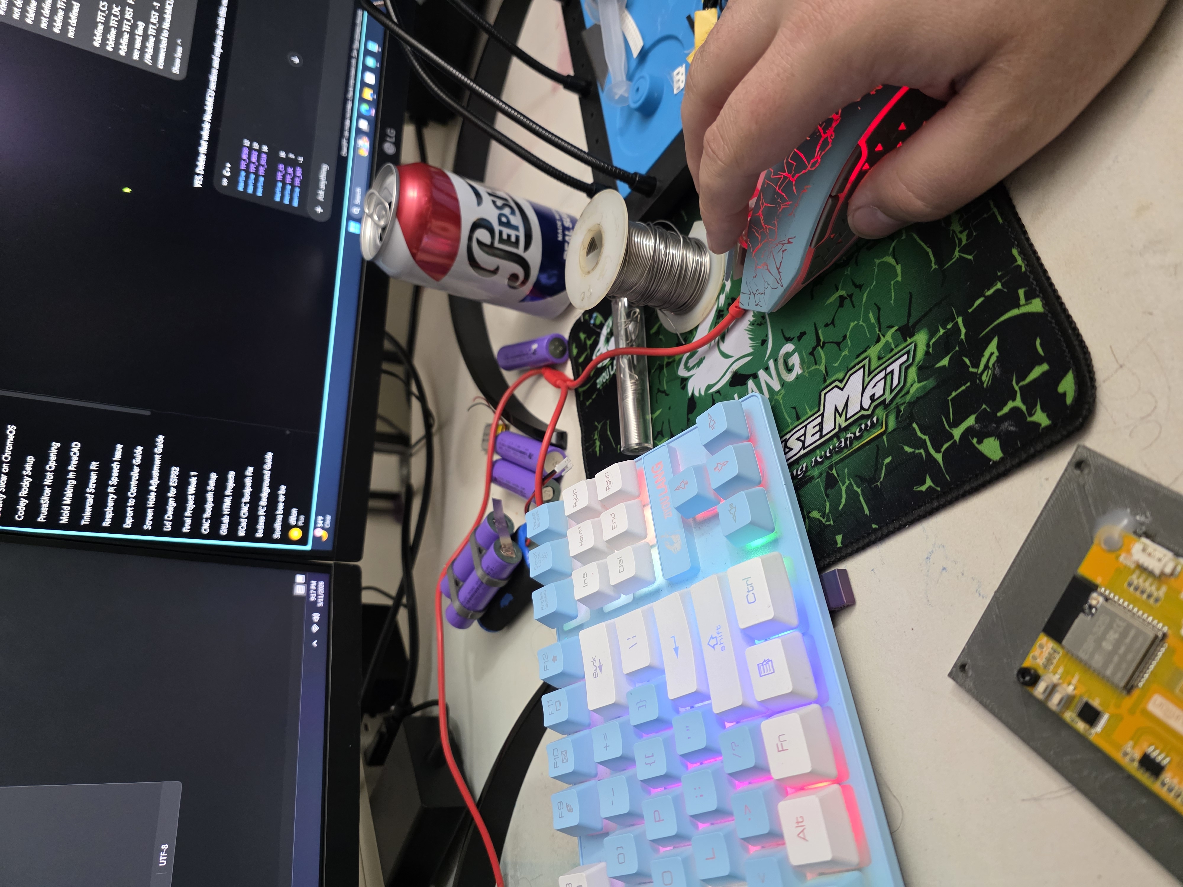
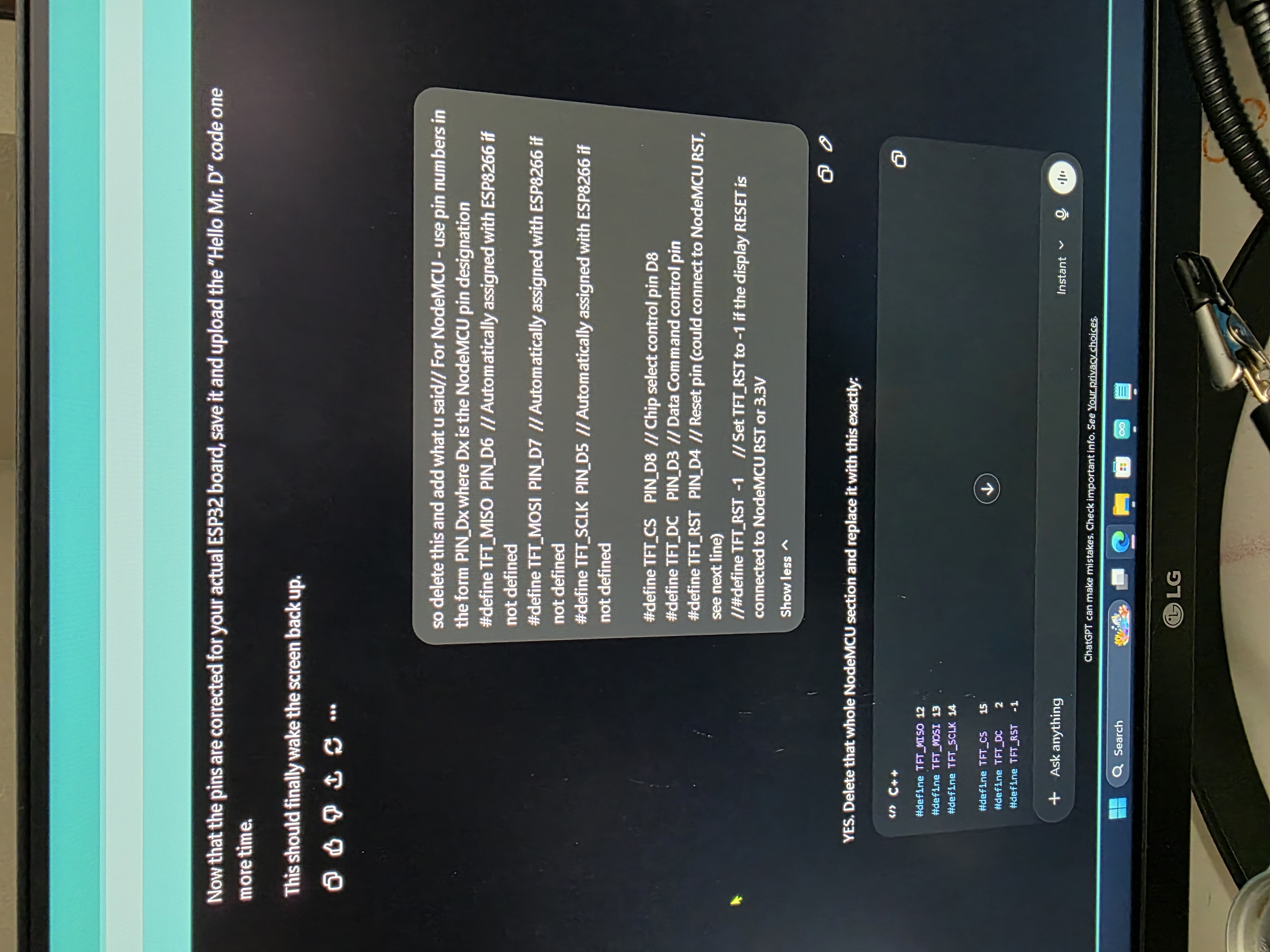
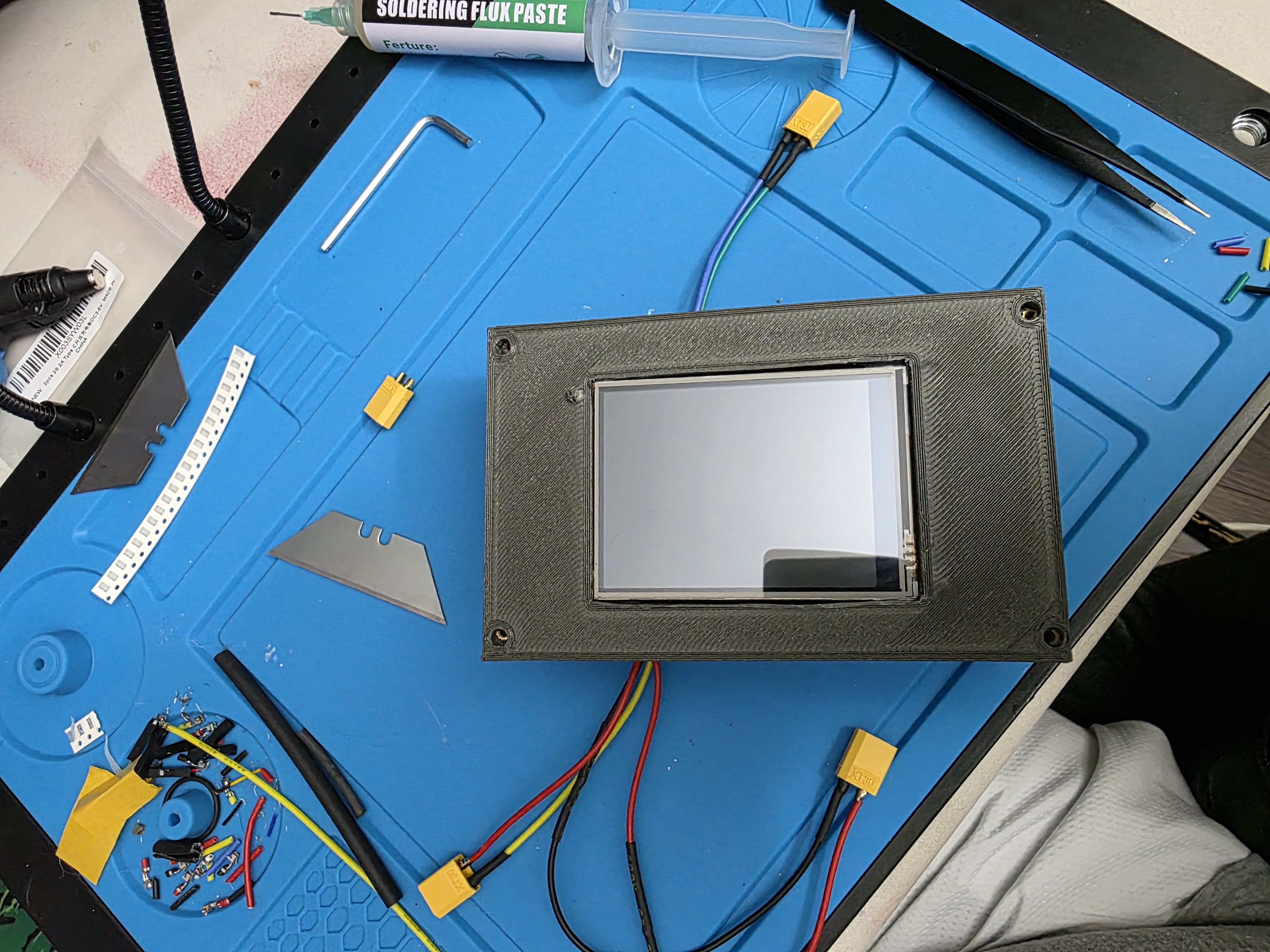
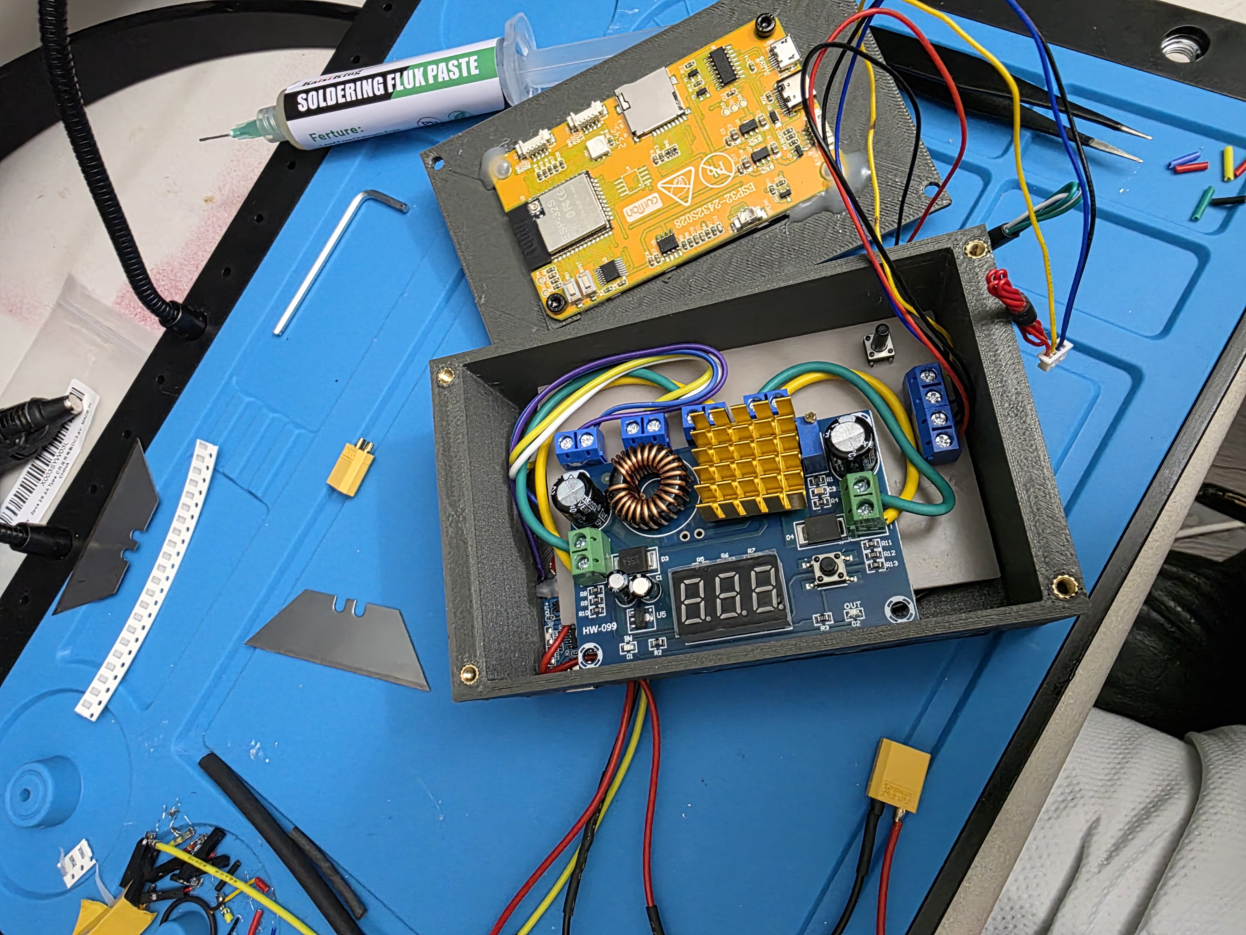
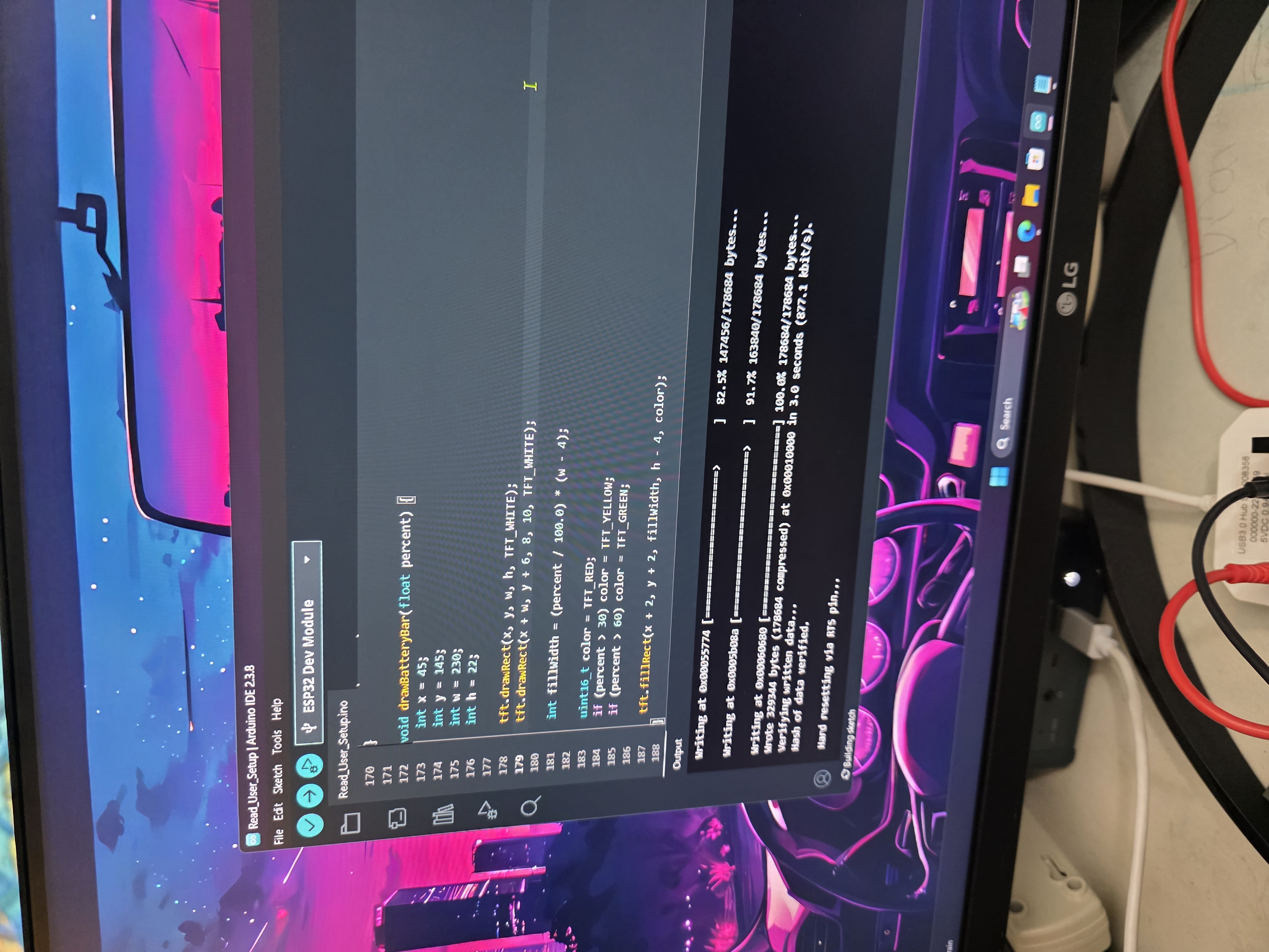
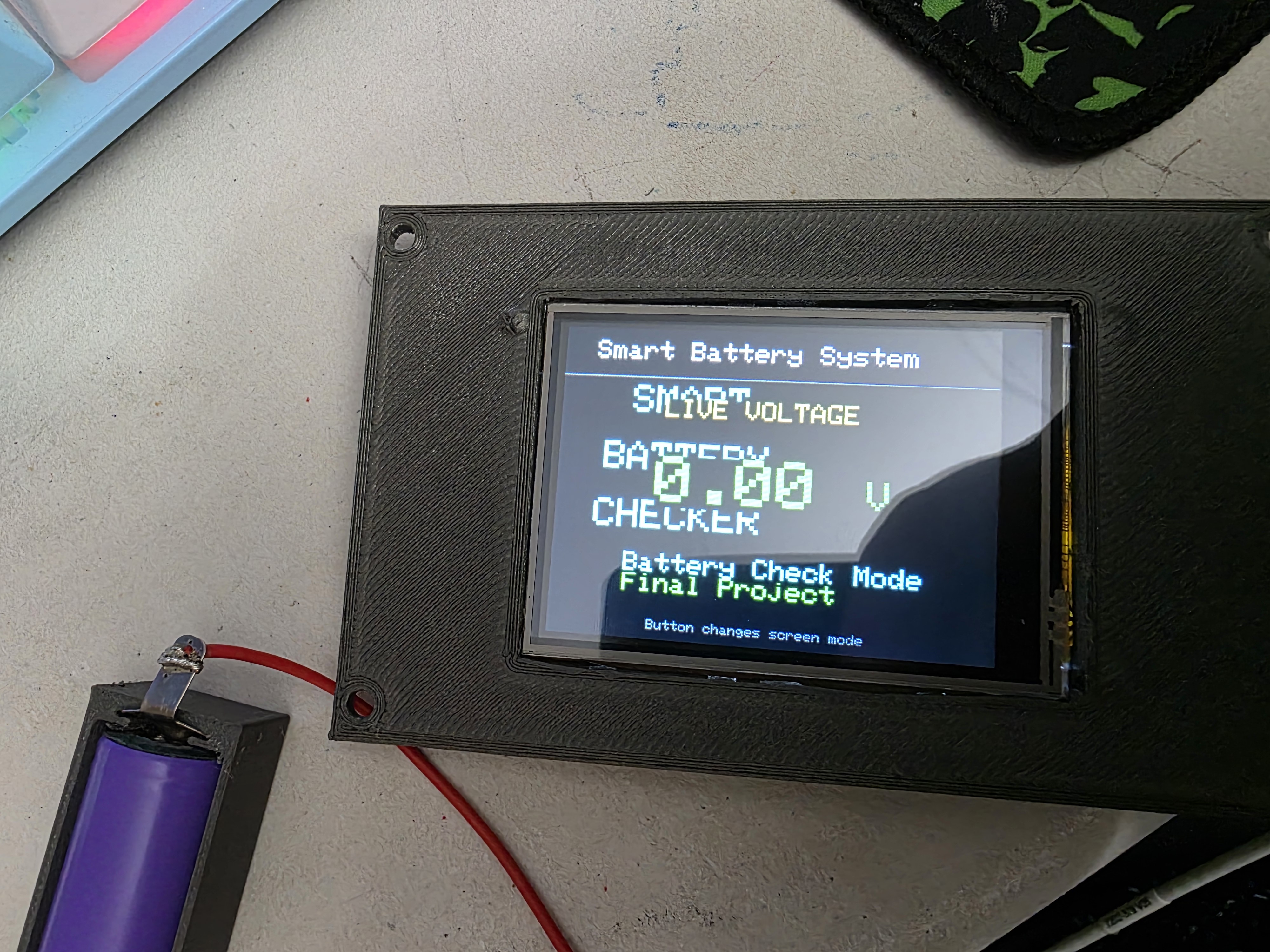
Assembly involved soldering electronics, routing wires, testing voltage readings, mounting components into the enclosure, and troubleshooting system integration problems.
Tools and Processes Used
- Makera Carvera CNC machine
- Arduino IDE
- ESP32 programming
- PCB milling
- Soldering
- 3D printing
- Laser cutting
- CAD design
- Voltage testing with multimeter
Problems During Development
Several PCB revisions were required because of trace spacing issues during milling. Some enclosure openings also needed resizing after test fitting the components.
During early testing, unstable readings and flickering values appeared until wiring and code changes improved the system stability.
What Worked
- ESP32 touchscreen displayed battery data correctly
- Custom PCB milled successfully
- Charging modules worked properly
- Voltage readings displayed correctly
- Button switching between modes worked
- Enclosure held all systems together successfully
What I Learned
This project brought together many of the skills learned throughout Fab Academy: electronics, fabrication, PCB production, embedded programming, troubleshooting, and system integration.
One of the biggest lessons was learning how much redesigning and troubleshooting happens during a real engineering project. Small wiring or PCB mistakes can affect the entire system.
Final Thoughts
I am proud that I was able to combine multiple fabrication and electronics systems into one working device capable of reading battery voltage and charging batteries while displaying information on a touchscreen interface.
Throughout the project I also used Astra, my ChatGPT assistant, to help explain concepts, troubleshoot issues, improve documentation, and help organize the development process.
Download Files
All source files used for this final project are available for download. This ZIP file contains the Arduino code, KiCad PCB files, Gerber files, CNC toolpaths, CAD files, STL files, project documentation, presentation, and supporting project resources used to develop SparkIon.