Week 11: Networking and Communications
Week 11 Assignment:
-
Group Assignment
- Send a message between two projects
-
Individual Assignment
- Design, build, and connect wired or wireless node(s) with network or bus addresses and local input &/or output device(s)
Notes from the Lecture
-
- location -> people are in different locations, so we network because of distance
- parallelism -> a processor can do one thing at a time, an operating system divide time for multiple tasks. So you can have one big processor and an operating system managing multiple tasks.
- modularity -> Or, you can spread it out, you have a little processor controlling a motor, another one controlling a sensor, another one controlling a display - each task goes into its own processor. You have the motor, the sensor, the display reading completely separately, debug them separately, and then plug them in. It makes the system easier to debug and more scalable.
- interference -> for example you might have high voltage or high current in one part of your system, also low level sensor signals in another part of the system. By separating and networking, you can prevent interference.
Purposes of networking and communications:
-> so for all those reasons, there are great reasons to make a network completely in a single final project to have multiple processors distributed even if you don’t have to network for geographical separation.
-
Wired Networks
- Peripherals to do serial communication: UART, USART, SERCOM, PIO, bit-bang
- Asynchronous Serial -> you just start talking
- serial broadcast
- hop-count
- broad-hop
- Synchronous Serial -> you are going to have a clock line and data line. The clock line tells you when to communicate.
- I2C -> it has SDA (data) and SCL (clock).
- SPI
- Asynchronous unlocked
-
OSI Layers:
- 7 -> application (HTTP), things like HTTP for web browsing
- 6 -> presentation (SSL), things like encryption
- 5 -> session (RPC), you may or may not see
- 4 -> transport (TCP, UDP), how you control the sending and receiving of messages
- 3 -> network (IP), how you route a message to have an address
- 2 -> data link (MAC), once you are connected to it, how you control who gets to talk when
- 1 -> physical (PHY), physical medium such as one wire, two wires, fiber optic or radio
-
Modulation -> how we modulate
- PCM: Pulse-Code Modulation -> amplitude
- PPM: Pulse-Position Modulation -> you control pulses in time
- OOK: On-Off Keying -> turn the signal on and off
- FSK: Frequency-Shift Keying -> shift frequency
- BPSK: Binary Phase-Shift Keying -> shift phase
- QAM: Quadrature Amplitude Modulation
- OFDM: Orthogonal Frequency-Division Multiplexing
- FHSS: Frequency-Hopping Spread Spectrum
- DSSS: Direct-Sequence Spread Spectrum
- UWB: Ultra-WideBand -> spread over a wide frequency range
-
Channel Sharing -> then you need to figure out who gets to talk when. so you can divide time slots, and you can also divide them in frequency.
- TDMA: Time-Division Multiple Access
- FDMA: Frequency-Divsion Multiple Access
- CSMA: Carrier-Sense Multiple Access *most common -> where you listen if nobody’s talking, you can start talking. If somebody’s talking, you wait a delay, but the delay has to be random. otherwise everybody would start at the same time. And after a random back off, you start talking, but you check if anybody collided.
GROUP ASSIGNMENT
Chai Huo Week 11 - Group Assignment
Idea
Create a simple musical instrument with two microcontrollers. Microcontroller 1 acts as the sender (providing input), and Microcontroller 2 acts as the receiver (producing output). It is very fast and has low power consumption.
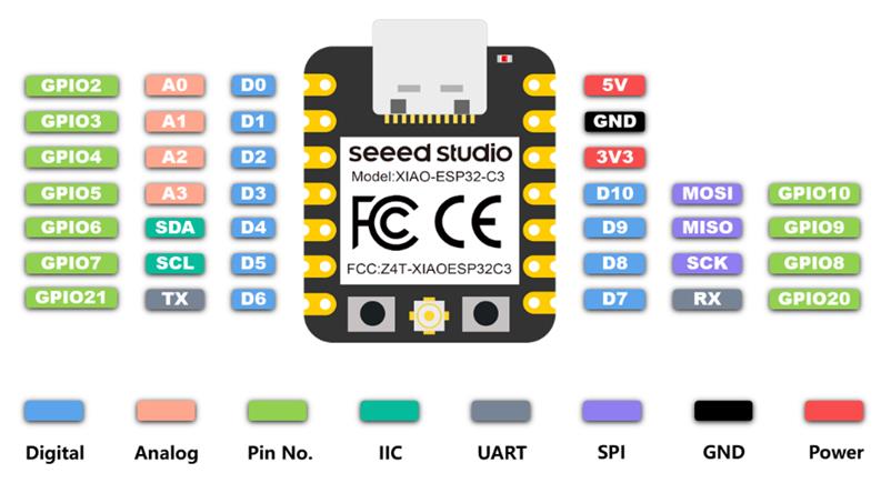
Connect 2 XIAO ESP32C3
ESP-NOW
ESP-NOW is a direct device-to-device communication protocol developed by Espressif Systems. It enables ESP devices to communicate with each other wirelessly without requiring a Wi-Fi router or an internet connection. This makes it suitable for fast, low-power, and short-range data exchange.
We are using ESP-NOW to connect 2 XIAO ESP32C3. It is a connectionless wireless protocol developed specifically for ESP chips. It allows the two microcontrollers to talk directly to each other without needing a Wi-Fi router, acting like a direct remote control. It is incredibly fast and perfect for this use case.
How ESP-NOW works: we need to find the MAC Address (the unique physical ID) of Microcontroller 2 (Receiver) and paste it into the code of your Microcontroller 1 (Sender) so it knows exactly where to send the data.
We need to upload this code to Microcontroller 2 (Receiver):
#include "WiFi.h"
void setup(){
  Serial.begin(115200);
  WiFi.mode(WIFI_MODE_STA);
  Serial.println(WiFi.macAddress());
}
void loop(){}
Open the Serial Monitor, and copy the MAC address it prints out:
Microcontroller 1 (Sender)
This code checks the buttons. If a button is pressed, it turns on the corresponding LED and sends a signal (a number from 1 to 5) via ESP-NOW to the receiver.
The connections:
- Button 1 -> GPIO 9
- Button 2 -> GPIO 8
- Button 3 -> GPIO 20
- Button 4 -> GPIO 21
-
Button 5 -> GPIO 7
-
LED 1 -> GPIO 2
- LED 2 -> GPIO 3
- LED 3 -> GPIO 4
- LED 4 -> GPIO 5
- LED 5 -> GPIO 6
Since the MAC address of Microcontroller 2 (Receiver) is 64:E8:33:8A:5B:00,
the receiverAddress will be {0x64, 0xE8, 0x33, 0x8A, 0x5B, 0x00}
(This code is generated from Gemini)
#include <esp_now.h>
#include <WiFi.h>

// REPLACE WITH THE MAC ADDRESS OF YOUR SECOND MICROCONTROLLER
// Example format: {0x34, 0x85, 0x18, 0x01, 0x02, 0x03}
uint8_t receiverAddress[] = {0x64, 0xE8, 0x33, 0x8A, 0x5B, 0x00};

// Define Pins
const int btnPins[5] = {9, 8, 20, 21, 7};
const int ledPins[5] = {2, 3, 4, 5, 6};

// Variable to store the last state of the buttons
int lastBtnState[5] = {HIGH, HIGH, HIGH, HIGH, HIGH};

// Structure to send data
typedef struct struct_message {
    int noteIndex; // Will send 1 for DO, 2 for RE, etc.
} struct_message;

struct_message myData;
esp_now_peer_info_t peerInfo;

void setup() {
  Serial.begin(115200);

  // Setup pins
  for (int i = 0; i < 5; i++) {
    pinMode(btnPins[i], INPUT_PULLUP); // Using internal pull-up resistors
    pinMode(ledPins[i], OUTPUT);
    digitalWrite(ledPins[i], LOW);     // LEDs off by default
  }

  // Set device as a Wi-Fi Station
  WiFi.mode(WIFI_STA);

  // Init ESP-NOW
  if (esp_now_init() != ESP_OK) {
    Serial.println("Error initializing ESP-NOW");
    return;
  }

  // Register peer (the receiver)
  memcpy(peerInfo.peer_addr, receiverAddress, 6);
  peerInfo.channel = 0;
  peerInfo.encrypt = false;

  if (esp_now_add_peer(&peerInfo) != ESP_OK){
    Serial.println("Failed to add peer");
    return;
  }
}

void loop() {
  for (int i = 0; i < 5; i++) {
    int currentState = digitalRead(btnPins[i]);

    // Check if button was pressed (LOW because of INPUT_PULLUP)
    if (currentState == LOW && lastBtnState[i] == HIGH) {
      digitalWrite(ledPins[i], HIGH); // Turn on LED

      myData.noteIndex = i + 1; // 1 to 5

      // Send message via ESP-NOW
      esp_err_t result = esp_now_send(receiverAddress, (uint8_t *) &myData, sizeof(myData));

      delay(50); // Debounce delay
    }
    // Check if button was released
    else if (currentState == HIGH && lastBtnState[i] == LOW) {
      digitalWrite(ledPins[i], LOW); // Turn off LED
      delay(50); // Debounce delay
    }

    lastBtnState[i] = currentState;
  }
}
Microcontroller 2 (Receiver)
The connections:
- OLED 0.96” -> SDA (GPIO 6), SCL (GPIO 7)
- Buzzer / Speaker -> GPIO 3
Buzzer
This code listens for ESP-NOW messages. When it receives a number (1-5), it updates the OLED screen and plays the corresponding frequency on the buzzer.
When Button 1, Button 2, Button 3, Button 4, or Button 5 is pressed on Microcontroller 1 (Sender), the OLED displays “DO”, “RE”, “MI”, “FA”, and “SOL”, while the buzzer plays the corresponding notes C4, D4, E4, F4, and G4.
(This code is generated from Gemini)
#include <esp_now.h>
#include <WiFi.h>
#include <Wire.h>
#include <Adafruit_GFX.h>
#include <Adafruit_SSD1306.h>

#define SCREEN_WIDTH 128
#define SCREEN_HEIGHT 64
// XIAO ESP32C3 default I2C: SDA is GPIO6 (D4), SCL is GPIO7 (D5)
Adafruit_SSD1306 display(SCREEN_WIDTH, SCREEN_HEIGHT, &Wire, -1);

const int buzzerPin = 3;

// Structure to receive data (must match sender)
typedef struct struct_message {
    int noteIndex;
} struct_message;
struct_message myData;

// Musical frequencies (C4, D4, E4, F4, G4)
const int noteFreqs[] = {262, 294, 330, 349, 392};
const String noteNames[] = {"DO", "RE", "MI", "FA", "SOL"};

// UPDATED Callback function for ESP32 Core v3.x
void OnDataRecv(const esp_now_recv_info * info, const uint8_t *incomingData, int len) {
  memcpy(&myData, incomingData, sizeof(myData));

  int idx = myData.noteIndex - 1; // Convert 1-5 to 0-4 array index

  if (idx >= 0 && idx <= 4) {
    // 1. Play Tone for 250 milliseconds
    tone(buzzerPin, noteFreqs[idx], 250);

    // 2. Update OLED Screen
    display.clearDisplay();
    display.setTextSize(4);
    display.setTextColor(SSD1306_WHITE);
    display.setCursor(30, 20); // Roughly center text
    display.print(noteNames[idx]);
    display.display();

    Serial.println("Played: " + noteNames[idx]);
  }
}

void setup() {
  Serial.begin(115200);

  // Initialize Buzzer
  pinMode(buzzerPin, OUTPUT);

  // Initialize OLED (Address 0x3C is standard for 0.96" OLEDs)
  if(!display.begin(SSD1306_SWITCHCAPVCC, 0x3C)) {
    Serial.println(F("SSD1306 allocation failed"));
    for(;;); // Don't proceed, loop forever
  }
  display.clearDisplay();
  display.setTextSize(2);
  display.setTextColor(SSD1306_WHITE);
  display.setCursor(10, 20);
  display.print("Waiting...");
  display.display();

  // Set device as a Wi-Fi Station
  WiFi.mode(WIFI_STA);

  // Init ESP-NOW
  if (esp_now_init() != ESP_OK) {
    Serial.println("Error initializing ESP-NOW");
    return;
  }

  // Register for recv callback
  esp_now_register_recv_cb(OnDataRecv);
}

void loop() {
  // Clear the screen if no note has been played recently (optional)
  // Everything is handled by the ESP-NOW callback in the background!
}
Now that the antenna is attached, both consoles are working.
Speaker
If you connect a Grove Speaker instead of a buzzer, you can use the same code but change the pin name from buzzerPin to speakerPin and make sure to connect the speaker to the correct GPIO pin.
When Button 1, Button 2, Button 3, Button 4, or Button 5 is pressed on Microcontroller 1 (Sender), the OLED displays “DO”, “RE”, “MI”, “FA”, and “SOL”, while the speaker plays the corresponding notes C4, D4, E4, F4, and G4.
(This code is generated from Gemini)
#include <esp_now.h>
#include <WiFi.h>
#include <Wire.h>
#include <Adafruit_GFX.h>
#include <Adafruit_SSD1306.h>

#define SCREEN_WIDTH 128
#define SCREEN_HEIGHT 64
// XIAO ESP32C3 default I2C: SDA is GPIO6 (D4), SCL is GPIO7 (D5)
Adafruit_SSD1306 display(SCREEN_WIDTH, SCREEN_HEIGHT, &Wire, -1);

// Changed variable name to reflect the new hardware
const int speakerPin = 3;

// Structure to receive data (must match sender)
typedef struct struct_message {
    int noteIndex;
} struct_message;
struct_message myData;

// Musical frequencies (C4, D4, E4, F4, G4)
const int noteFreqs[] = {262, 294, 330, 349, 392};
const String noteNames[] = {"DO", "RE", "MI", "FA", "SOL"};

// Callback function for ESP32 Core v3.x
void OnDataRecv(const esp_now_recv_info * info, const uint8_t *incomingData, int len) {
  memcpy(&myData, incomingData, sizeof(myData));

  int idx = myData.noteIndex - 1; // Convert 1-5 to 0-4 array index

  if (idx >= 0 && idx <= 4) {
    // 1. Play Tone for 250 milliseconds on the Grove Speaker
    tone(speakerPin, noteFreqs[idx], 250);

    // 2. Update OLED Screen
    display.clearDisplay();
    display.setTextSize(4);
    display.setTextColor(SSD1306_WHITE);
    display.setCursor(30, 20); // Roughly center text
    display.print(noteNames[idx]);
    display.display();

    Serial.println("Played: " + noteNames[idx]);
  }
}

void setup() {
  Serial.begin(115200);

  // Initialize Speaker Pin
  pinMode(speakerPin, OUTPUT);

  // Initialize OLED (Address 0x3C is standard for 0.96" OLEDs)
  if(!display.begin(SSD1306_SWITCHCAPVCC, 0x3C)) {
    Serial.println(F("SSD1306 allocation failed"));
    for(;;); // Don't proceed, loop forever
  }
  display.clearDisplay();
  display.setTextSize(2);
  display.setTextColor(SSD1306_WHITE);
  display.setCursor(10, 20);
  display.print("Waiting...");
  display.display();

  // Set device as a Wi-Fi Station
  WiFi.mode(WIFI_STA);

  // Init ESP-NOW
  if (esp_now_init() != ESP_OK) {
    Serial.println("Error initializing ESP-NOW");
    return;
  }

  // Register for recv callback
  esp_now_register_recv_cb(OnDataRecv);
}

void loop() {
  // Clear the screen if no note has been played recently (optional)
  // Everything is handled by the ESP-NOW callback in the background!
}
Now that the antenna is attached, both consoles are working.
(23 April 2026)
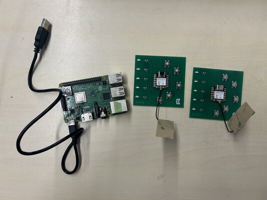
Since we were previously using a breadboard for this experiment, we repeated the setup using a PCB fabricated with a CNC machine.
We used a different XIAO ESP32C3 for the new PCB, so we needed to determine the MAC address of this microcontroller.
To do this, we checked it using the following code in the Arduino IDE:
#include "WiFi.h"
void setup(){
  Serial.begin(115200);
  WiFi.mode(WIFI_MODE_STA);
  Serial.println(WiFi.macAddress());
}
void loop(){}
After uploading the code, open the Serial Monitor and copy the MAC address displayed:
You can find the MAC address shown at the bottom, as illustrated below: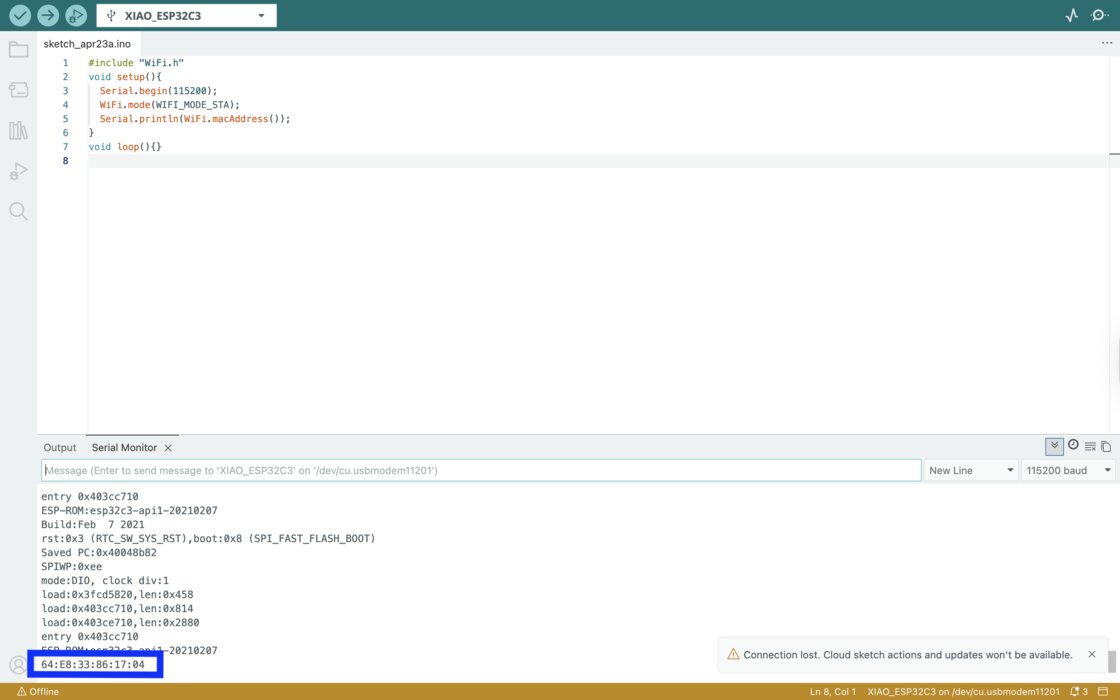
Therefore, we need to update the code for Microcontroller 1 (Sender) by replacing it with the MAC address of the new Microcontroller 2 (Receiver): 64:E8:33:86:17:04
#include <esp_now.h>
#include <WiFi.h>

// REPLACE WITH THE MAC ADDRESS OF YOUR SECOND MICROCONTROLLER
// Example format: {0x34, 0x85, 0x18, 0x01, 0x02, 0x03}
uint8_t receiverAddress[] = {0x64, 0xE8, 0x33, 0x86, 0x17, 0x04};

// Define Pins
const int btnPins[5] = {9, 8, 20, 21, 7};
const int ledPins[5] = {2, 3, 4, 5, 6};

// Variable to store the last state of the buttons
int lastBtnState[5] = {HIGH, HIGH, HIGH, HIGH, HIGH};

// Structure to send data
typedef struct struct_message {
    int noteIndex; // Will send 1 for DO, 2 for RE, etc.
} struct_message;

struct_message myData;
esp_now_peer_info_t peerInfo;

void setup() {
  Serial.begin(115200);

  // Setup pins
  for (int i = 0; i < 5; i++) {
    pinMode(btnPins[i], INPUT_PULLUP); // Using internal pull-up resistors
    pinMode(ledPins[i], OUTPUT);
    digitalWrite(ledPins[i], LOW);     // LEDs off by default
  }

  // Set device as a Wi-Fi Station
  WiFi.mode(WIFI_STA);

  // Init ESP-NOW
  if (esp_now_init() != ESP_OK) {
    Serial.println("Error initializing ESP-NOW");
    return;
  }

  // Register peer (the receiver)
  memcpy(peerInfo.peer_addr, receiverAddress, 6);
  peerInfo.channel = 0;
  peerInfo.encrypt = false;

  if (esp_now_add_peer(&peerInfo) != ESP_OK){
    Serial.println("Failed to add peer");
    return;
  }
}

void loop() {
  for (int i = 0; i < 5; i++) {
    int currentState = digitalRead(btnPins[i]);

    // Check if button was pressed (LOW because of INPUT_PULLUP)
    if (currentState == LOW && lastBtnState[i] == HIGH) {
      digitalWrite(ledPins[i], HIGH); // Turn on LED

      myData.noteIndex = i + 1; // 1 to 5

      // Send message via ESP-NOW
      esp_err_t result = esp_now_send(receiverAddress, (uint8_t *) &myData, sizeof(myData));

      delay(50); // Debounce delay
    }
    // Check if button was released
    else if (currentState == HIGH && lastBtnState[i] == LOW) {
      digitalWrite(ledPins[i], LOW); // Turn off LED
      delay(50); // Debounce delay
    }

    lastBtnState[i] = currentState;
  }
}
INDIVIDUAL ASSIGNMENT
This week, I tried to connect a Raspberry Pi and XIAO ESP32C3 using a wireless network (Wi-Fi / HTTP).
Idea
The idea is based on my final project: a game console. I want to create a quiz game console with a “Raise Hand” button. When a player presses the button on the XIAO ESP32C3 (client), the Raspberry Pi (server) will record who pressed first: Console 1 or Console 2.
HTTP over Wi-Fi
This is the standard way devices connect using a wireless network. Devices communicate using internet protocols such as HTTP, allowing them to interact with web servers, cloud platforms, and mobile applications. This method works over a local network or the internet, supports large amounts of data transfer compared to ESP-NOW, but generally consumes more power and has higher latency.
Server: Raspberry Pi

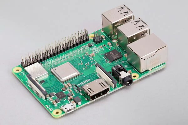
Materials:
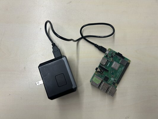
- Raspberry Pi 3 Model B+
- Micro USB Cable
- USB power supply
Headless Setup (SSH Connection)
In order to make things easier, I set up the Raspberry Pi in headless mode, so I can control it from my laptop without using a monitor.
I followed this tutorial: Raspberry Pi Headless Setup in 5 Minutes (No Monitor Needed)
-
Make sure your laptop and Raspberry Pi are connected to the same WiFi
-
Open your terminal on your laptop and type:
-> change username and hostname according to your username and hostname, for example:
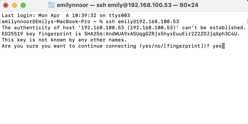
ssh emily@192.168.100.53They will ask:
This key is not known by any other names.
Are you sure you want to continue connecting (yes/no/[fingerprint])?
And I answered: “yes”
-
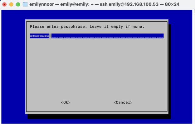
Enter your password
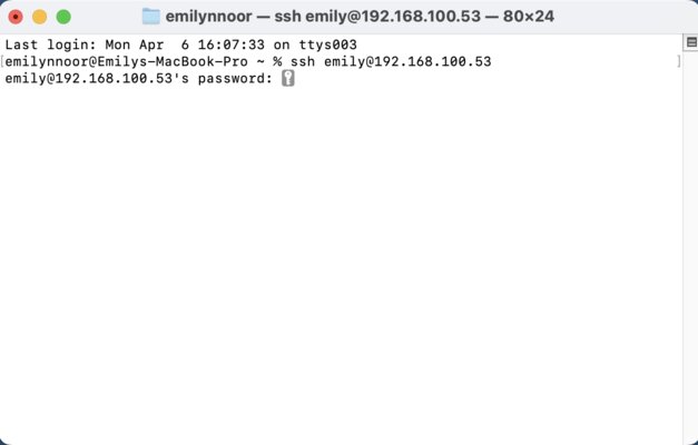
Note
the password will not be visible when typing!
-
If successful, the terminal prompt will change:
emily@emily:~ $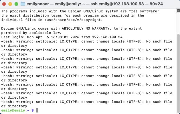
Setting up Raspberry Pi as the Server
-
Update system and install Python:
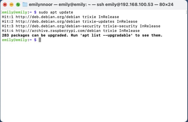
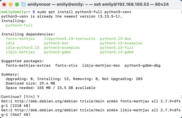
-
Create a virtual environment (for example: venv)
-
Activate the virtual environment
my terminal prompt changed and show “venv” at the start:
(venv) emily@emily:~ $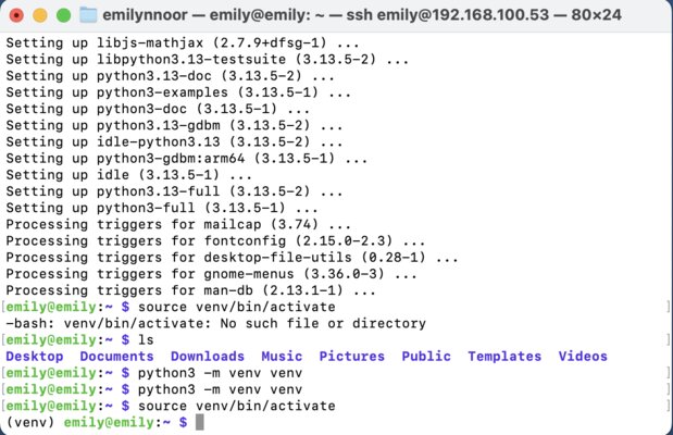
-
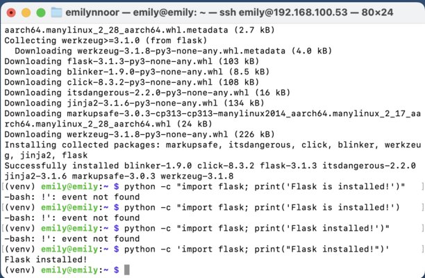
Next, install Flask inside the virtual environment. Flask is a “micro” web framework written in Python. It is used to build the backend of web applications, handling the server-side logic that processes user requests and returns data to a browser.
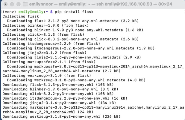
then test if the flask is installed successfully or not:
-
Create a new Python file for the quiz. For example I wrote:
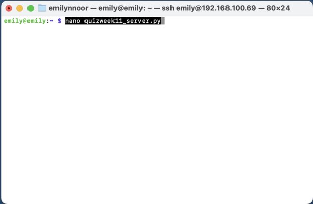
and then wrote this code: (This code is generated from ChatGPT)
from flask import Flask, request
import time

app = Flask(__name__)

first_buzzer = None
start_time = None

@app.route("/start")
def start():
    global first_buzzer, start_time
    first_buzzer = None
    start_time = time.time()
    return "Quiz started!"

@app.route("/buzz")
def buzz():
    global first_buzzer, start_time

    player = request.args.get("player")

    if start_time is None:
        return "Game not started"

    if first_buzzer is None:
        first_buzzer = player
        elapsed = time.time() - start_time
        print(f"{player} pressed first! ({elapsed:.3f}s)")
        return "You are FIRST!"

    return "Too late!"

if __name__ == "__main__":
    app.run(host="0.0.0.0", port=5000)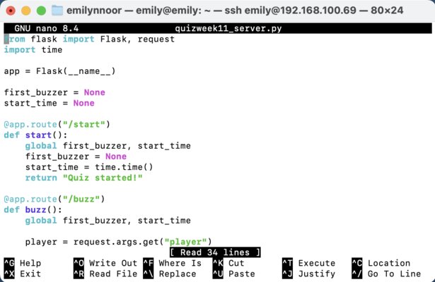
After writing the code, press Ctrl+O (Save) -> Enter -> Ctrl+X (Exit)
-> At this point, the code exists as a file on my Pi
-
Run the server:
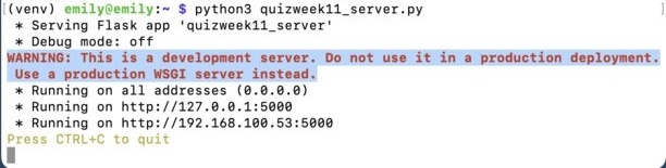
Output:
Running on http://0.0.0.0:5000/
This means your server is listening for HTTP requests.
Any device on the same WiFi network can now access the server at: http://192.168.100.53:5000
Client: XIAO ESP32C3
Next, we need to set up the XIAO ESP32C3. XIAO ESP32C3 has WiFi feature.
Materials:
- 2 × XIAO ESP32C3 (with antenna)
- Button + LED circuit (from Week 6)
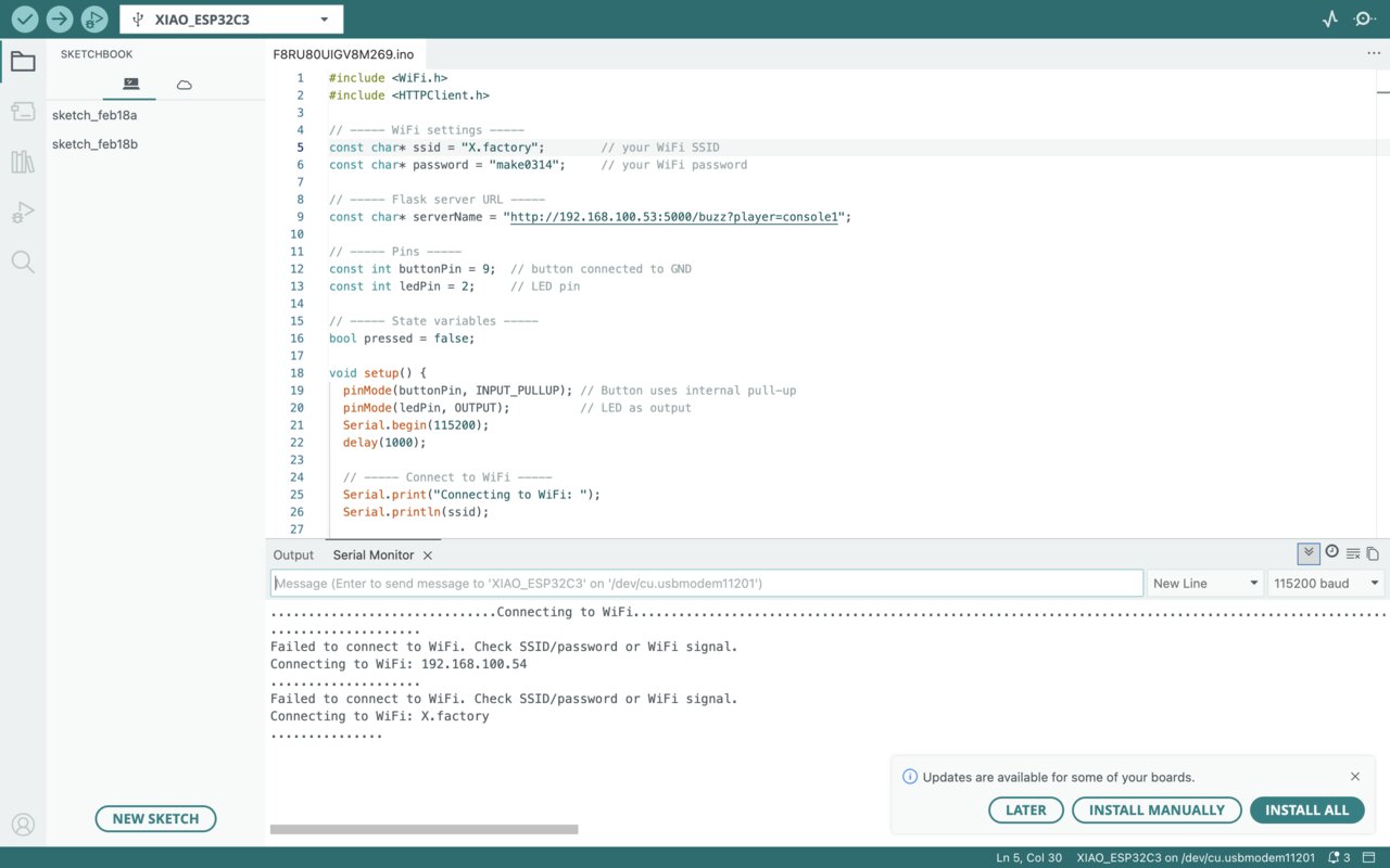
Mistake & Debugging
Initially, I used the WiFi network:
SSID: X.factory
Password: make0314
However, the ESP32 could not connect:
To debug this, I used a WiFi scanning code to check available networks:
#include "WiFi.h"

void setup() {
Serial.begin(115200);

// Set WiFi to station mode and disconnect from an AP if it was previously connected
WiFi.mode(WIFI_STA);
WiFi.disconnect();
delay(100);

Serial.println("Setup done");
}

void loop() {
Serial.println("scan start");

// WiFi.scanNetworks will return the number of networks found
int n = WiFi.scanNetworks();
Serial.println("scan done");
if (n == 0) {
    Serial.println("no networks found");
} else {
    Serial.print(n);
    Serial.println(" networks found");
    for (int i = 0; i < n; ++i) {
    // Print SSID and RSSI for each network found
    Serial.print(i + 1);
    Serial.print(": ");
    Serial.print(WiFi.SSID(i));
    Serial.print(" (");
    Serial.print(WiFi.RSSI(i));
    Serial.print(")");
    Serial.println((WiFi.encryptionType(i) == WIFI_AUTH_OPEN) ? " " : "*");
    delay(10);
    }
}
Serial.println("");

// Wait a bit before scanning again
delay(5000);
}
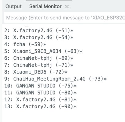
It turned out that the ESP32C3 could not detect “X.factory”.
-> This is because: The ESP32C3 only supports 2.4 GHz WiFi, not 5 GHz.
Therefore, I switched to a 2.4 GHz network:
SSID: X.factory2.4G
Then I updated both: - Raspberry Pi WiFi settings - ESP32C3 WiFi credentials
Change WiFi on Raspberry Pi
-
Open the terminal and run:
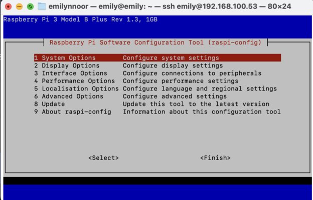
-
Navigate to:
1 System Options Configure system settingsand then,
S1 Wireless LAN Configure wireless LAN -
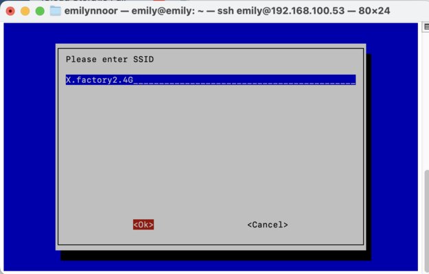
Enter new SSID and password
-
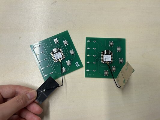
Connect the included WiFi/Bluetooth antenna to the IPEX connector on the XIAO ESP32C3 board
If you’re using the WiFi feature, don’t forget to use the antenna!
-
Connect XIAO ESP32C3 to the computer via a USB Type-C cable
-
Open Arduino IDE and wrote this code:
(This code is generated from ChatGPT)
I want the ESP32C3 to:
- Connects to WiFi
- Detects button press
- Sends HTTP request to Raspberry Pi
- Turns LED ON when pressed
#include <WiFi.h>
#include <HTTPClient.h>

const char* ssid = "X.factory2.4G";
const char* password = "make0314";

const char* serverName = "http://192.168.100.53:5000/buzz?player=console1"; // it must be the same server as Raspberry Pi

const int buttonPin = 9;
const int ledPin = 2;   // LED on GPIO 2

bool pressed = false;

void setup() {
pinMode(buttonPin, INPUT_PULLUP);
pinMode(ledPin, OUTPUT);      // set LED pin as output
digitalWrite(ledPin, LOW);    // LED starts OFF

Serial.begin(115200);

WiFi.begin(ssid, password);
while (WiFi.status() != WL_CONNECTED) {
    delay(500);
}

Serial.println("WiFi connected!");
}

void loop() {
int buttonState = digitalRead(buttonPin);

// Button pressed
if (buttonState == LOW && !pressed) {
    pressed = true;

    digitalWrite(ledPin, HIGH);   // 🔥 turn LED ON

    if (WiFi.status() == WL_CONNECTED) {
    HTTPClient http;
    http.begin(serverName);
    int httpResponseCode = http.GET();

    Serial.print("HTTP Response: ");
    Serial.println(httpResponseCode);

    http.end();
    }
}

// Button released
if (buttonState == HIGH && pressed) {
    pressed = false;

    digitalWrite(ledPin, LOW);    // 💡 turn LED OFF
}

delay(50); // debounce
}
Start the Quiz
-
SSH into Raspberry Pi:
-
Enter password
-
Activate environment:
-
Run the program:
-
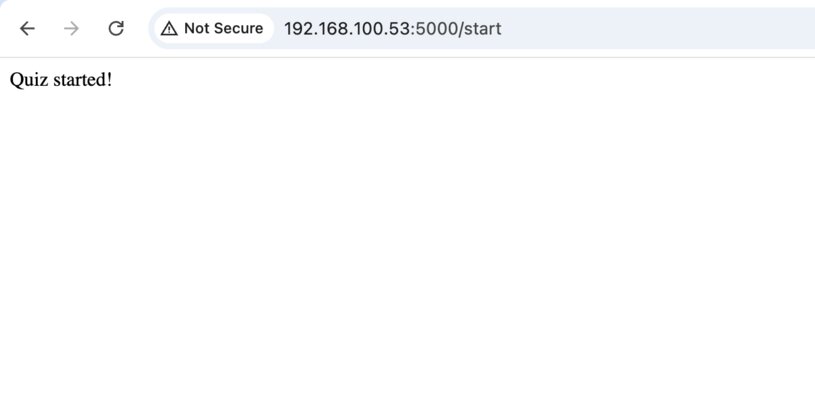
Open browser (I am using Chrome) and write this link:
The message ‘Quiz started!’ appears in the browser.
At the same time, in the terminal, it will show up something like this:
-
When a button is pressed:
- The ESP32 sends a request to the server
-
The Raspberry Pi prints:
console1 pressed first! (85.749s)-> WINNER -
Additional presses are ignored:
GET /buzz?player=console2-> TOO LATE
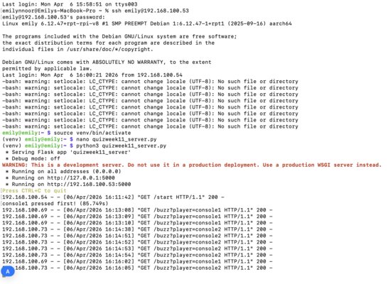
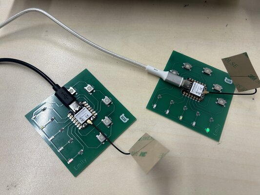
In this video below, Console 1 presses the button first, while Console 2 does not function properly because it does not have an antenna attached:
Now that the antenna is attached, both consoles are working.
WiFi/Bluetooth Antenna
The antenna is what actually sends and receives wireless signals (Wi-Fi and Bluetooth).
Without it, the microcontroller cannot transmit signals effectively, cannot receive signals reliably and has very week or almost zero range.
Notes
- The system works using HTTP requests over WiFi
- The Raspberry Pi determines the winner (first request received)
- Make sure to use XIAO ESP32C3 with the antenna, the signal is so much better
- This setup can be extended into a full quiz game system with scoring, UI, and A/B/C/D multiple choices
Pi IP Address Keep Changing
On 6 April, my Pi’s IP address was 192.168.100.53. The next day, when I tried to connect via SSH, this IP no longer worked. Therefore, I had to check the Pi’s current IP address using a keyboard and monitor with the command:
For example, if the new IP is 192.168.100.69, I can connect via SSH using this updated address.