Week 10: Output Devices
Week 10 Assignment:
-
Group Assignment
- Measure the power consumption of an output device
-
Individual Assignment
- Add an output device to a microcontroller board you’ve designed, and program it to do something
GROUP ASSIGNMENT
Chai Huo Week 10 - Group Assignment
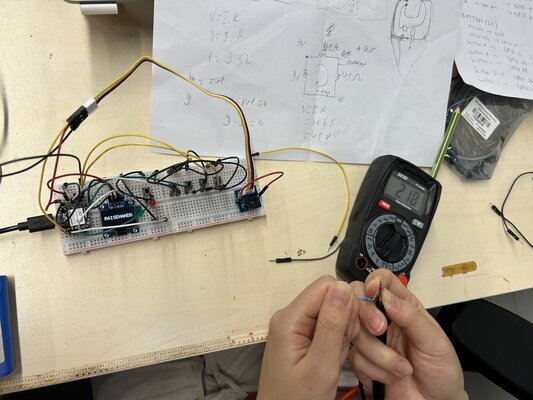
Power Consumption of different LEDs
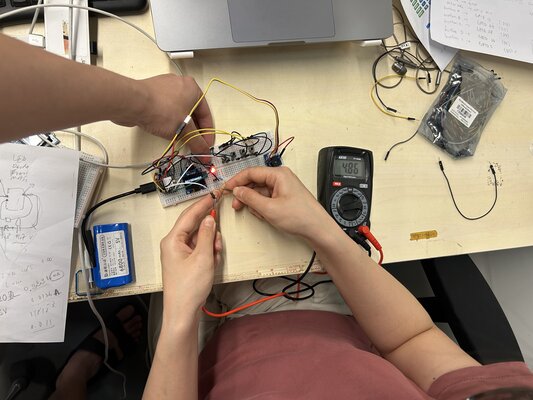
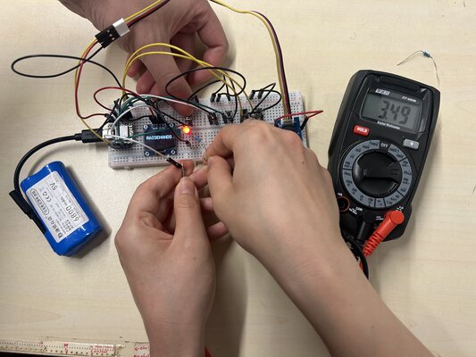
I measured the power consumption of an LED from this circuit using different resistors.
Power can be calculated using the following equation:
Power (W) = Voltage (V) × Current (I)
Ohm’s Law:
Voltage (V) = Current (I) × Resistance (R)
-
Experiment 1: Using a 218 Ω Resistor
-
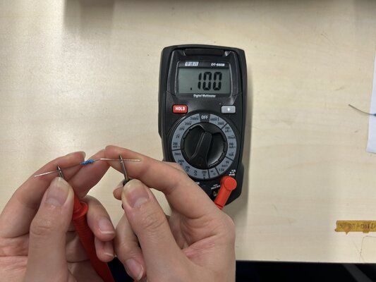
Step 1: Measuring Resistance
I measured the resistance of the first resistor: 218 Ω
-
Step 2: Measuring Voltage (LED & Resistor)
Using a multimeter:
-
The voltage across the LED + resistor is 2.99 V
-
The voltage across the LED only is 1.87 V
-
Therefore, the voltage across the resistor only is: 2.99 V − 1.87 V = 1.12 V
-
-
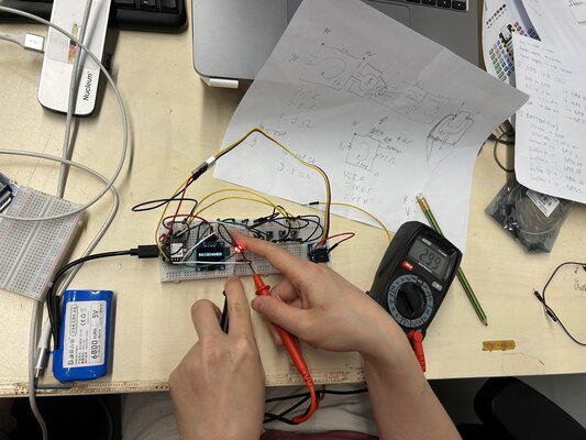
Step 3: Measuring Current
Calculated Current: Since I know the voltage across the resistor (1.12 V) and its resistance (218 Ω), I used Ohm’s Law (I = V / R) to calculate the current:
I = 1.12 V / 218 Ω = 5.14 mAMeasured Current: I also measured the current using a multimeter: 4.86 mA
The Difference
-> The calculated current (5.14 mA) and measured current (4.86 mA) are close. The difference may be due to measurement error or component tolerances.
-
Step 4: Calculating Power
I calculated the power consumption of the LED based on the measured values:
P = 1.87 V × 4.86 mA = 0.009 W = 9.1 mW
-
-
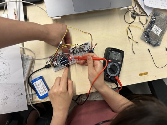
Experiment 2: Using a 100 Ω Resistor
-
Step 1: Measuring Resistance
I measured the resistance of the first resistor: 100 Ω
-
Step 2: Measuring Voltage (LED & Resistor)
Using a multimeter:
-
The voltage across the LED + resistor is 2.99 V
-
The voltage across the LED only is 1.87 V
-
Therefore, the voltage across the resistor only is: 2.99 V − 1.87 V = 1.12 V
-
-
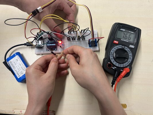
Step 3: Measuring Current
Calculated Current: Since I know the voltage across the resistor (1.12 V) and its resistance (218 Ω), I used Ohm’s Law (I = V / R) to calculate the current:
I = 1.12 V / 100 Ω = 11.2 mAMeasured Current: I also measured the current using a multimeter: 7.66 mA
-
Step 4: Calculating Power
I calculated the power consumption of the LED based on the measured values:
P = 1.87 V × 7.66 mA = 0.014 W = 14.32 mW
-
-
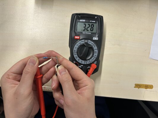
Experiment 3: Using a 328 Ω Resistor
-
Step 1: Measuring Resistance
I measured the resistance of the first resistor: 328 Ω
-
Step 2: Measuring Voltage (LED & Resistor)
Using a multimeter:
-
The voltage across the LED + resistor is 2.99 V
-
The voltage across the LED only is 1.87 V
-
Therefore, the voltage across the resistor only is: 2.99 V − 1.87 V = 1.12 V
-
-
Step 3: Measuring Current
Calculated Current: Since I know the voltage across the resistor (1.12 V) and its resistance (218 Ω), I used Ohm’s Law (I = V / R) to calculate the current:
I = 1.12 V / 328 Ω = 3.41 mAMeasured Current: I also measured the current using a multimeter: 3.49 mA
-
Step 4: Calculating Power
I calculated the power consumption of the LED based on the measured values:
P = 1.87 V × 3.49 mA = 0.0065 W = 6.53 mW
-
Summary
| Resistor Resistance (R) | LED Voltage (V) | Current (I) | Power (V x I) |
|---|---|---|---|
| 100 Ω | 1.87 V | 7.66 mA | 14.32 mW |
| 218 Ω | 1.87 V | 4.86 mA | 9.1 mW |
| 328 Ω | 1.87 V | 3.49 mA | 6.53 mW |
- Higher resistance -> lower current (Ohm’s Law)
- Lower current -> lower power (since P = V x I)
Power Consumption of the 0.91” OLED Display
Second, I measured the power consumption of the 0.91” OLED display using a DC power supply.
I connected the black cable to GND and the red cable to the 5V pin.

Next, I set the voltage on the DC power supply to 5.00 V and the current limit to 0.100 A.
Then, I turned on the power supply.
The measured power consumption was:
5 V × 0.031 A = 0.155 W
Then, I repeated the same process.
it showed slightly different value:
5 V x 0.033 A = 0.165 W
The small difference in power consumption may be caused by normal fluctuations in current measurement or slight changes in the OLED display’s operating condition. Overall, the OLED display consumes approximately 0.16 W of power during operation.
INDIVIDUAL ASSIGNMENT
This week, I experimented with different kinds of output devices, including LCD, OLED, Buzzer and LED.
LCD vs OLED
-
LCD (Liquid Crystal Display) -> There are backlight (a big light source in the back) and a layer of liquid crystals in front. The response time is slower, the crystals have to move/rotate to change color.
-
OLED (Organic Light-Emitting Diode) -> Unlike LCD, OLED doesn’t have backlight. Each individual pixel is made of organic material that glows when you give it electricity. The response time is instant: when electricity hits the organic material, it changes light output immediately.
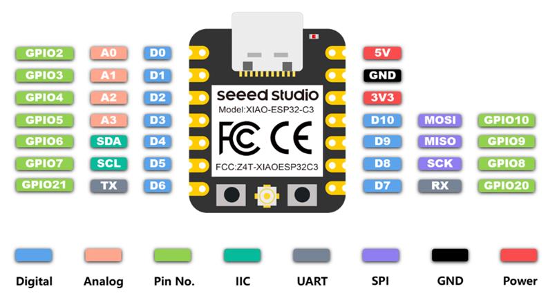
For all the experiments, I used the XIAO ESP32C3 as the microcontroller.
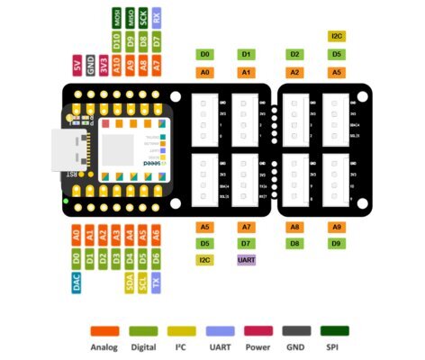
Moreover, I used the Grove Shield for XIAO as an expansion board. This board acts as a bridge between the Seeed Studio XIAO and the Grove modules.
As the CNC milling machine was not ready yet, I used the Grove Shield for XIAO and a breadboard to explore output devices. This documentation has been kept for reference. You can go to Using My Own PCB to see output testing done with my custom PCB manufactured using CNC milling (updated on 23 April 2026).
Using Grove Shield for XIAO & Breadboard
LCD RGB Backlight, LCD (White on Blue)
-
Prepare the materials needed:
- XIAO ESP32C3
- Grove Base for XIAO
- Grove - LCD RGB Backlight
Grove - LCD RGB Backlight:
It enables the user to set any color preference with a simple and concise Grove interface.
Features:
- RGB Backlight
- I2C communication
- Built-in English and Japanese fonts
- 16x2 LCD
Specifications:
Item Value Input Voltage 3.3/5V Operating Current <60mA CGROM 10880 bit CGRAM 64x8 bit LCD I2C Address 0X3E RGB I2C Address 0X62 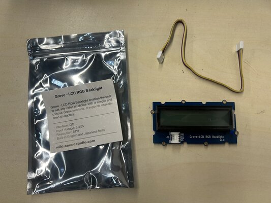
-
Connect Grove-LCD RGB Backlight to I2C port of Grove Base
-
Plug XIAO ESP32C3 to Grove Base
-
Connect XIAO ESP32C3 to PC via a USB-C cable
-
Download the Grove-LCD RGB Backlight Library from Github
-
Open Arduino IDE. Click on
Sketch -> Include Library -> Add .ZIP Library -
Check if the library install correctly. Click on
File -> Examples -> Grove - LCD RGB Backlight -> choose an example, I chose “HelloWorld”.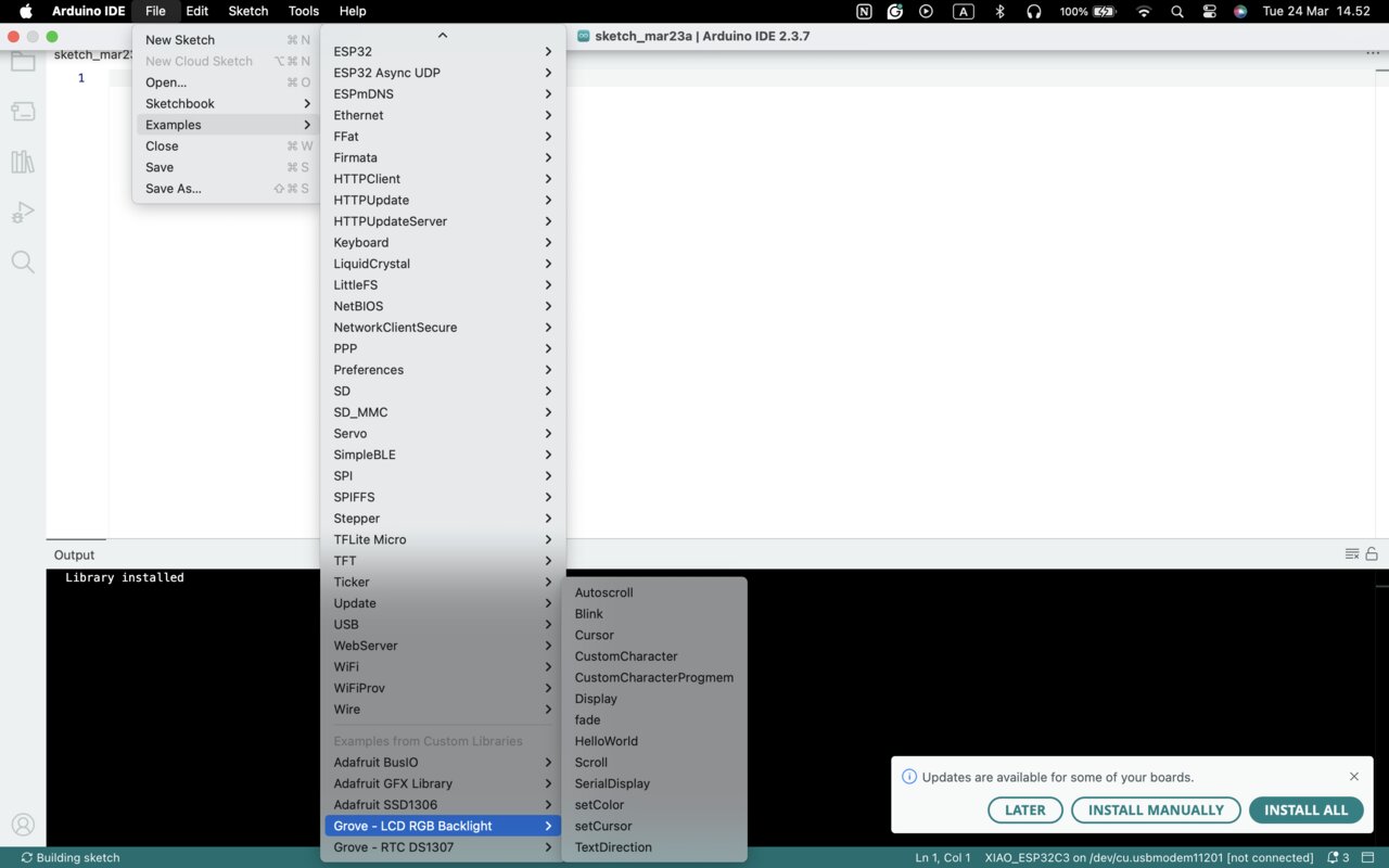
There are 13 examples in the library:
Autoscroll,Blink,Cursor,CustomCharacter,CustomCharacterProgmem,Display,fade,HelloWorld,Scroll,SerialDisplay,setColor,setCursor,TextDirection -
I uploaded the code, but somehow it didn’t work. It only showed red RGB backlight on the Grove - LCD RGB Backlight.
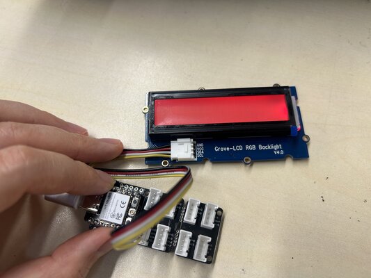
LCD not working
- Power and RGB backlight chip are working (I2C part at address 0x62)
- The LCD controller (text driver, usually 0x3E) is not communicating properly
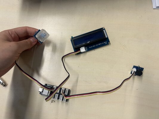
I tried to use another LCD: Grove - 16x2 LCD (White on Blue), and it worked well:
Grove - 16x2 LCD (White on Blue):
It enables the user to set any color preference with a simple and concise Grove interface.
Features:
- Display construction: 16 Characters, 2 Lines
- Display mode: STN
- On board MCU
- I2C-bus interface
- Support English and Japanese fonts
Specifications:
Item Value Operating Voltage 3.3V / 5V Operating temperature 0 to 50℃ Storage temperature -10 to 60℃ Driving method 1/16 duty, 1/5 bias Interface I2C I2C Address 0X3E
Buzzer
Since I am going to use OLED/LCD and buzzer for my final project, I want to experiment with these output components together. I followed this experiment: Toothbrushing Instructor
-
Prepare the materials needed:
- XIAO ESP32C3
- Grove Base for XIAO
- Grove - Mech Keycad
- Grove - 16x2 LCD (White on Blue)
- Grove - Buzzer
Grove - Buzzer:
This module has a piezo buzzer which can be connected to digital outputs and it will emit a tone when the output is HIGH. It can also be connected to an analog pulse-width modulation output to generate various tones and effects.
Feature:
- Easy to use piezoelectric buzzer
- Uses Standard 4-pin Grove Cables to connect to other Grove modules such as - Grove Power Modules and Grove - Base Shield
- Digital port
Specifications:
Item Value Operating Voltage 3.3V/5V Sound Output ≥85dB Resonant Frequency 2300±300Hz 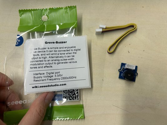
-
Connect Grove - 16x2 LCD to port I2C, Grove - Mech Keycad to port D0, and Grove - Buzzer to port D2 of Grove Base
-
Plug XIAO ESP32C3 to Grove Base
-
Connect XIAO ESP32C3 to PC via a USB-C cable
-
Copy the following code into Arduino IDE and upload the code:
This code is generated from ChatGPT
#include <Wire.h> #include "rgb_lcd.h" rgb_lcd lcd; const int buzzerPin = D2; const int buttonPin = D0; // LCD color (blue) const int colorR = 0; const int colorG = 0; const int colorB = 200; void setup() { Wire.begin(); lcd.begin(16, 2); lcd.setRGB(colorR, colorG, colorB); lcd.setCursor(0, 0); lcd.print("TIME 2:00"); lcd.setCursor(0, 1); lcd.print("PRESS BUTTON"); pinMode(buzzerPin, OUTPUT); pinMode(buttonPin, INPUT); } void loop() { if (digitalRead(buttonPin) == HIGH) { delay(200); // simple debounce StartToothBrushTimer(); } delay(100); } void StartToothBrushTimer() { int totalSeconds = 120; for (int i = totalSeconds; i >= 0; i--) { int minute = i / 60; int second = i % 60; lcd.clear(); lcd.setCursor(0, 0); // format time if (second < 10) lcd.print("TIME: " + String(minute) + ":0" + String(second)); else lcd.print("TIME: " + String(minute) + ":" + String(second)); // buzz every 30 sec if (second == 0 || second == 30) { doBuzz(); lcd.setCursor(0, 1); if (i > 90) lcd.print("OUTSIDE TOP"); else if (i > 60) lcd.print("INSIDE TOP"); else if (i > 30) lcd.print("OUTSIDE BOT"); else lcd.print("INSIDE BOT"); } delay(1000); } lcd.clear(); lcd.setCursor(0, 0); lcd.print("TIME 2:00"); lcd.setCursor(0, 1); lcd.print("PRESS BUTTON"); } void doBuzz() { digitalWrite(buzzerPin, HIGH); delay(200); digitalWrite(buzzerPin, LOW); } -
Press the button (Grove – Mech Keycap) and the counter will start. A ‘beep’ sound will come from the buzzer.
OLED, LED, Buzzer
These are all the output devices (OLED 0.96”, LED, and Buzzer) I will use for my final projects. So I want to experiment with these materials.
-
Prepare the materials needed:
- XIAO ESP32C3
- OLED 0.96” (I tested the I2C connection of the OLED 0.96” with logic analyzer. I documented it on Week 6 (Logic Analyzer))
- Button 5x
- LED + Resistor
- Grove - Buzzer
- Jumper Wires
- Breadboard (I acknowledge that is not recommended to use the breadboard due to its problem in wiring connections, but the CNC milling is not ready to use yet, and I just want to temporary check the circuit. If everything is already ok, maybe I will order the PCB to PCB design house)
-
I simulate the circuit in Wokwi.
-
Then, I connected all the materials with the XIAO ESP32C3:
-
OLED 0.96”
- GND -> GND
- VCC -> 3.3V
- SCC -> GPIO 7
- SDA -> GPIO 6
-
Button 5x:
- Button A -> GPIO 10
- Button B -> GPIO 9
- Button C -> GPIO 8
- Button D -> GPIO 20
- Button 1 -> GPIO 5
- the other side of the buttons going to GND
-
LED + resistor:
- GPIO 4 -> Resistor -> LED (+)
- LED (-) -> GND
-
Buzzer
- GND -> GND
- VCC -> 5V
- SIG -> GPIO 3
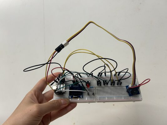
The final set up:
-
-
Connect XIAO ESP32C3 to PC via a USB-C cable
-
Copy the following code into Arduino IDE and upload the code:
This code is generated from ChatGPT
#include <Wire.h> #include <Adafruit_GFX.h> #include <Adafruit_SSD1306.h> #define SCREEN_WIDTH 128 #define SCREEN_HEIGHT 64 Adafruit_SSD1306 display(SCREEN_WIDTH, SCREEN_HEIGHT, &Wire, -1); // -------- PIN DEFINITIONS -------- // Buttons #define BTN_A 10 #define BTN_B 9 #define BTN_C 8 #define BTN_D 20 #define BTN_1 5 // Outputs #define LED_PIN 4 #define BUZZER_PIN 3 // -------- LED TIMER -------- unsigned long ledTimer = 0; bool ledOn = false; const int LED_DURATION = 500; // 0.5 seconds // -------- SETUP -------- void setup() { Serial.begin(115200); // I2C init (SDA = 6, SCL = 7) Wire.begin(6, 7); // OLED init if (!display.begin(SSD1306_SWITCHCAPVCC, 0x3C)) { Serial.println("OLED not found"); while (true); } showCentered("AWL READY?"); // Button inputs pinMode(BTN_A, INPUT_PULLUP); pinMode(BTN_B, INPUT_PULLUP); pinMode(BTN_C, INPUT_PULLUP); pinMode(BTN_D, INPUT_PULLUP); pinMode(BTN_1, INPUT_PULLUP); // Outputs pinMode(LED_PIN, OUTPUT); pinMode(BUZZER_PIN, OUTPUT); } // -------- MAIN LOOP -------- void loop() { if (pressed(BTN_1)) { showCentered("RAISEHANDS"); beep(); turnOnLED(); delay(200); } if (pressed(BTN_A)) { showCentered("A"); beep(); turnOnLED(); delay(200); } if (pressed(BTN_B)) { showCentered("B"); beep(); turnOnLED(); delay(200); } if (pressed(BTN_C)) { showCentered("C"); beep(); turnOnLED(); delay(200); } if (pressed(BTN_D)) { showCentered("D"); beep(); turnOnLED(); delay(200); } // LED auto OFF after 0.5 seconds if (ledOn && millis() - ledTimer > LED_DURATION) { digitalWrite(LED_PIN, LOW); ledOn = false; } } // -------- FUNCTIONS -------- bool pressed(int pin) { return digitalRead(pin) == LOW; } void turnOnLED() { digitalWrite(LED_PIN, HIGH); ledTimer = millis(); ledOn = true; } // Improved beep using tone void beep() { tone(BUZZER_PIN, 1000); // 1000 Hz sound delay(150); noTone(BUZZER_PIN); } void showCentered(String text) { display.clearDisplay(); display.setTextSize(2); display.setTextColor(WHITE); int16_t x, y; uint16_t w, h; display.getTextBounds(text, 0, 0, &x, &y, &w, &h); int centerX = (SCREEN_WIDTH - w) / 2; int centerY = (SCREEN_HEIGHT - h) / 2; display.setCursor(centerX, centerY); display.print(text); display.display(); } -
First, the OLED will show ‘AWL READY?’
If you press Button 1, the OLED will show ‘RAISEHANDS’.
If you press Button 2, the OLED will show ‘A’.
If you press Button 3, the OLED will show ‘B’.
If you press Button 4, the OLED will show ‘C’.
If you press Button 4, the OLED will show ‘D’.
In every button press, the LED will turn on for 0.5s and the buzzer will sound ‘beep’.
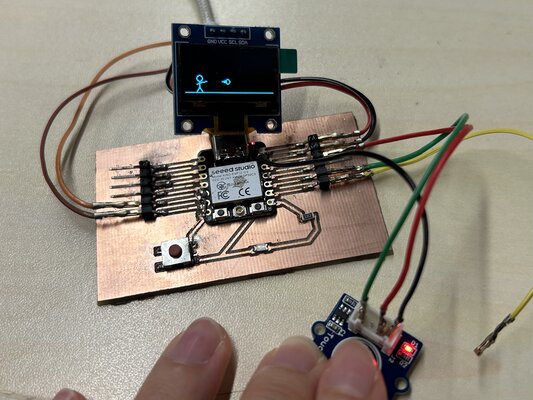
Using My Own PCB
(Updated on 23 April 2026)
In this experiment, I used the OLED display (0.96”, I²C) as the output device to visualize interactions triggered by the Grove Touch Sensor.
-
Prepare the materials needed:
- XIAO ESP32C3
- Jumper Wires
- OLED display (0.96”, I²C)
- Grove - Touch Sensor
OLED display (0.96”, I²C)
The 0.96-inch OLED display is a compact monochrome screen commonly used in embedded systems. It is based on the SSD1306 driver and communicates via the I²C protocol, requiring only two data lines (SDA and SCL).
Key Features:
- Resolution: 128 × 64 pixels
- Interface: I²C (address typically 0x3C)
- Low power consumption (no backlight required)
- High contrast and visibility, even in low-light conditions
- Suitable for text, graphics, and simple animations
-
Circuit Connections:
- Connect the Grove Touch Sensor signal pin to GPIO 9
- Connect the OLED display: SDA -> GPIO 6 and SCL -> GPIO 7
-
Power Connection:
Connect the XIAO ESP32C3 to your computer using a USB-C cable.
-
Upload the Code:
Copy and upload the following code using the Arduino IDE:
(This code is generated from Gemini)
#include <Wire.h> #include <Adafruit_GFX.h> #include <Adafruit_SSD1306.h> #define SCREEN_WIDTH 128 #define SCREEN_HEIGHT 64 #define OLED_RESET -1 #define SCREEN_ADDRESS 0x3C // Define Touch Pin #define TOUCH_PIN 9 Adafruit_SSD1306 display(SCREEN_WIDTH, SCREEN_HEIGHT, &Wire, OLED_RESET); // Stickman variables const int personX = 20; // Moved to the left side of the screen const int personY = 40; bool isThrowing = false; int throwTimer = 0; // Keeps the throwing pose on screen briefly // Fireball System (Allow up to 3 fireballs at once) const int MAX_FIREBALLS = 3; struct Fireball { float x; float y; bool active; }; Fireball fireballs[MAX_FIREBALLS]; float fireSpeed = 4.0; // Speed of the fireball void setup() { // The Grove Touch Sensor actively drives HIGH/LOW, so standard INPUT is used pinMode(TOUCH_PIN, INPUT); // Initialize I2C for XIAO ESP32C3 Wire.begin(6, 7); if(!display.begin(SSD1306_SWITCHCAPVCC, SCREEN_ADDRESS)) { for(;;); } // Initialize fireballs to inactive for (int i = 0; i < MAX_FIREBALLS; i++) { fireballs[i].active = false; } display.clearDisplay(); display.display(); } void drawStickman(int x, int y, bool throwing) { // Head display.drawCircle(x, y, 4, SSD1306_WHITE); // Torso display.drawLine(x, y + 4, x, y + 12, SSD1306_WHITE); // Legs display.drawLine(x, y + 12, x - 4, y + 18, SSD1306_WHITE); display.drawLine(x, y + 12, x + 4, y + 18, SSD1306_WHITE); if (throwing) { // Arm pointing forward (throwing action) display.drawLine(x, y + 6, x - 4, y + 8, SSD1306_WHITE); // Back arm display.drawLine(x, y + 6, x + 10, y + 4, SSD1306_WHITE); // Front arm extended } else { // Arms resting at sides display.drawLine(x, y + 7, x - 5, y + 10, SSD1306_WHITE); display.drawLine(x, y + 7, x + 5, y + 10, SSD1306_WHITE); } } void drawFireball(int x, int y) { // Draw a simple fireball (a circle with a triangular tail) display.drawCircle(x, y, 3, SSD1306_WHITE); display.fillTriangle(x - 2, y - 2, x - 8, y, x - 2, y + 2, SSD1306_WHITE); } void loop() { static bool lastTouchState = LOW; bool currentTouchState = digitalRead(TOUCH_PIN); // Detect Touch (Rising Edge: Sensor goes HIGH when touched) if (currentTouchState == HIGH && lastTouchState == LOW) { isThrowing = true; throwTimer = 8; // Keep the throwing pose for 8 frames // Spawn a fireball for (int i = 0; i < MAX_FIREBALLS; i++) { if (!fireballs[i].active) { fireballs[i].x = personX + 12; // Start just ahead of the stickman's hand fireballs[i].y = personY + 4; fireballs[i].active = true; break; // Only spawn one per tap } } } lastTouchState = currentTouchState; // Handle the throwing animation timer if (throwTimer > 0) { throwTimer--; } else { isThrowing = false; // Return to resting pose } // Update fireball positions for (int i = 0; i < MAX_FIREBALLS; i++) { if (fireballs[i].active) { fireballs[i].x += fireSpeed; // Deactivate the fireball if it goes off the right edge of the screen if (fireballs[i].x > SCREEN_WIDTH + 10) { fireballs[i].active = false; } } } // --- Rendering --- display.clearDisplay(); // Draw the ground display.drawLine(0, 59, 128, 59, SSD1306_WHITE); // Draw the character drawStickman(personX, personY, isThrowing); // Draw all active fireballs for (int i = 0; i < MAX_FIREBALLS; i++) { if (fireballs[i].active) { drawFireball((int)fireballs[i].x, (int)fireballs[i].y); } } display.display(); delay(20); // 50 frames per second for smooth movement } -
Expected Output:
- A stickman character is displayed on the left side of the OLED screen.
- When the touch sensor is pressed:
- The stickman briefly changes into a throwing pose
- A fireball animation is generated from the character’s hand
- The fireball moves horizontally across the screen from left to right
- The system supports up to three fireballs simultaneously, allowing multiple quick touches to create overlapping animations.
- Once a fireball exits the screen, it is removed automatically.
- The animation runs smoothly at approximately 50 frames per second, creating a simple interactive visual effect.