Week 9: Input Devices
Week 9 Assignment:
-
Group Assignment
- Probe an input device’s analog levels and digital signals
-
Individual Assignment
- Measure something: add a sensor to a microcontroller board that you have designed and read it
Notes from the Lecture
-
they are multiple ways to get input in:
- ports / pins
- comparator -> the one who will told you voltage is higher or lower. you can do it quickly
- A/D (Analog to Digital converter) -> give you a voltage and give you the number
- I2C -> digital protocol we use, digital signal
-
READ THE DATA SHEET to know what the hardware actually does
GROUP ASSIGNMENT
Chai Huo Week 9 - Group Assignment
An Input Device’s Analog Levels and Digital Signals
Digital Signals
For the Week 9 assignment, I checked the digital signal from the Grove Touch Sensor.
I connected the probe tip to the 3.3V pin and the ground clip to GND.
The oscilloscope displayed the following waveform:
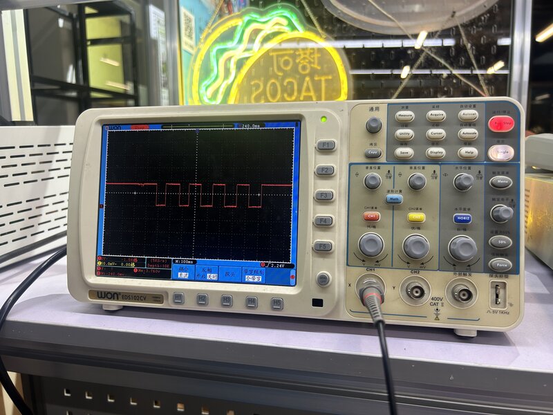
The vertical axis shows Voltage, while the horizontal axis shows Time.
For the vertical axis:
The vertical scale is 2V per square The waveform height is around 1.75 squares
This means:
Voltage = 2V × 1.75 = approximately 3.3V
For the horizontal axis:
The scale is 100 ms per square One full cycle takes 2 squares
This means:
Time per cycle = 100 ms × 2 = 200 ms
The signal shows approximately 3.3V and 200 ms per cycle.
The waveform starts at the HIGH state (top) and goes LOW (down) each time the touch sensor is pressed.
This indicates a pull-down behavior, where pressing the sensor changes the signal from HIGH to LOW.
INDIVIDUAL ASSIGNMENT
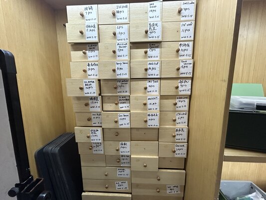
The input devices cardboard at Chaihuo Makers Space contains various modules, most of which are from Seeed’s Grove system.
This week, I experimented with different kinds of input devices, including a temperature sensor, touch sensor, mechanical keypad, thumb joystick, PIR motion sensor and RTC (Real-Time Clock).
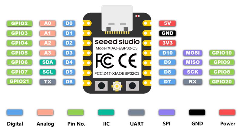
For all the experiments, I used the XIAO ESP32C3 as the microcontroller.
The next part uses the Grove Base for XIAO to test different input devices. It helped me explore input devices more easily, so I’ve kept this documentation. Go to Using my own PCB to see testing done with my custom PCB made using CNC milling (updated on 23 April 2026).
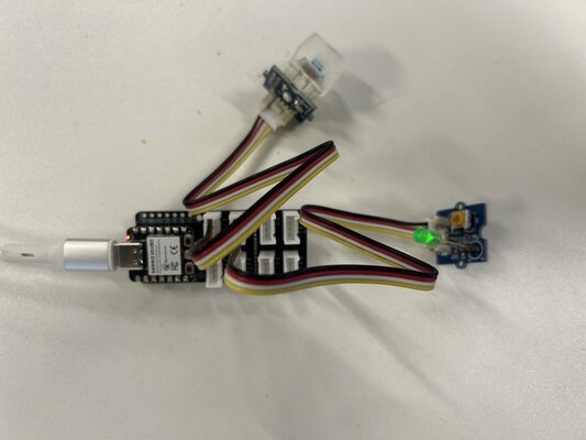
Using Grove Base for XIAO
Since all of the input devices are part of Seeed’s Grove ecosystem, I used the Grove Base for XIAO as an expansion board. This board acts as a bridge between the Seeed Studio XIAO and the Grove modules.
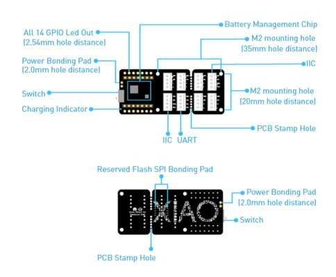
Grove Base for XIAO Information:
Feature:
- On-board Lithium Battery Charging and Management Function
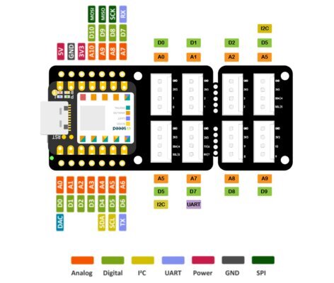
- Grove connectors ( Grove IIC x 2, Grove UART x 1 ), all 14 GPIO led out
- Compact and Breakable Design
- Flash SPI Bonding Pad Reserved
- On-board Power Switch and Charging Status Indicator Light
Specifications:
| Item | Value |
|---|---|
| Operating Voltage | 3.3V / 3.7V Lithium Battery |
| Load Capacity | 800mA |
| Charging Current | 400mA (Max) |
| Operating Temperature | - 40°C to 85°C |
| Storage Temperature | -55°C to 150°C |
| Grove Interface | I2C 2 / UART 1 |
For programming, I used the Arduino IDE.
1. Temperature Sensor
-
Prepare the materials needed:
- XIAO ESP32C3
- Grove Base for XIAO
- Grove - Temperature Sensor V1.2
Grove - Temperature Sensor V1.2:
This temperature sensor measures ambient temperature (the temperature of the surrounding environment) using a thermistor. It operates within a range of −40 to 125 °C and has an accuracy of ±1.5 °C.
Specifications:
Item Value Voltage 3.3V ~ 5V Zero Power Resistance 100 KΩ Resistance Tolerance ±1% Operating Temperature Range -40 ~ +125 ℃ Nominal B-Constant 4250 ~ 4299K 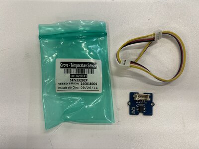
-
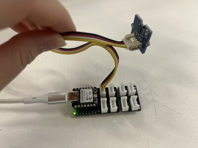
Connect Grove - Temperature Sensor to port A0 of Grove Base
-
Plug XIAO ESP32C3 to Grove Base
-
Connect XIAO ESP32C3 to PC via a USB-C cable
-
Copy the following code into Arduino IDE and upload the code:
#include <math.h>

const int B = 4275000;            // B value of the thermistor
const int R0 = 100000;            // R0 = 100k
const int pinTempSensor = A0;     // Grove Temperature Sensor on A0

float filteredTemp = 0;

// Read averaged ADC value
float readADC(int pin) {
long sum = 0;
const int samples = 20;

for (int i = 0; i < samples; i++) {
    sum += analogRead(pin);
    delay(5);
}

return sum / (float)samples;
}

void setup() {
Serial.begin(115200);
delay(1000);

analogSetPinAttenuation(pinTempSensor, ADC_11db); // improve range
}

void loop() {
float a = readADC(pinTempSensor);

// Convert ADC to resistance
float R = R0 * (4095.0 / a - 1.0);

// Convert resistance to temperature
float temperature = 1.0 / (log(R / R0) / B + 1 / 298.15) - 273.15;

// Smooth output (low-pass filter)
if (filteredTemp == 0) {
    filteredTemp = temperature; // initialize
} else {
    filteredTemp = 0.85 * filteredTemp + 0.15 * temperature;
}

// Output
Serial.print("Raw Temp: ");
Serial.print(temperature, 3);

Serial.print(" | Filtered Temp: ");
Serial.println(filteredTemp, 3);

delay(200);
}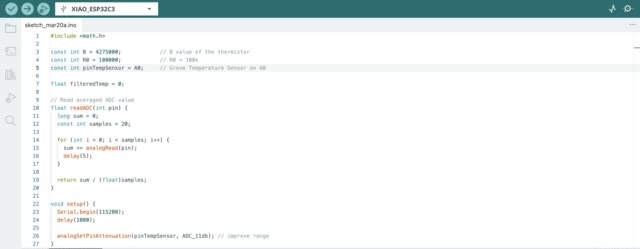
-
Open the Serial Monitor in the Arduino IDE by clicking
Tools -> Serial Monitor. You should see results in the Serial Monitor, as shown below.
It is shown that the temperature at that time is 25°C.
2. Touch Sensor
-
Prepare the materials needed:
- XIAO ESP32C3
- Grove Base for XIAO
- Grove - LED Socket & LED
- Grove - Touch Sensor
Grove - Touch Sensor:
This sensor enables touch-based input by sensing capacitance changes caused by a nearby finger.
Specifications:
Item Value Operating Voltage 2.0V - 5.5V Operating Current(Vcc=3V) 1.5 - 3.0μA Operating Current(VDD=3V) 3.5 - 7.0μA Output Response Time 60 - 220ms Used Chipset TTP223-BA6 Interface Digital Port 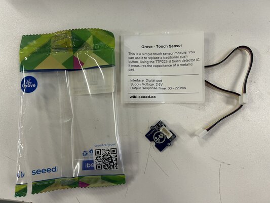
-
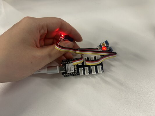
Connect Grove - Touch Sensor to port D0 and Grove LED Socket to port D1 of Grove Base
-
Plug XIAO ESP32C3 to Grove Base
-
Connect XIAO ESP32C3 to PC via a USB-C cable
-
Copy the following code into Arduino IDE and upload the code:
6. The LED turns on when we place our finger near the sensor, and it turns off when we move our finger away.const int TouchPin = D0; const int ledPin = D1; void setup() { pinMode(TouchPin, INPUT); pinMode(ledPin, OUTPUT); } void loop() { int sensorValue = digitalRead(TouchPin); if (sensorValue == HIGH) { digitalWrite(ledPin, HIGH); } else { digitalWrite(ledPin, LOW); } }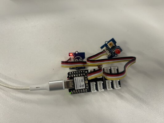
3. Mech Keypad
-
Prepare the materials needed:
- XIAO ESP32C3
- Grove Base for XIAO
- Grove - LED Socket & LED
- Grove - Mech Keycap
Grove - Mech Keypad:
A mechanical switch with a build-in LED
Features
- Programmable LED
- Reliable mechanical structure
- Extremely long operating Life
Specifications:
Item Value Operating Voltage 3.0V - 5.0V Insulation Resistance 100MΩ Min Contract Resistance 200 mΩ Max Operating Life without Load 20,000,000 times press 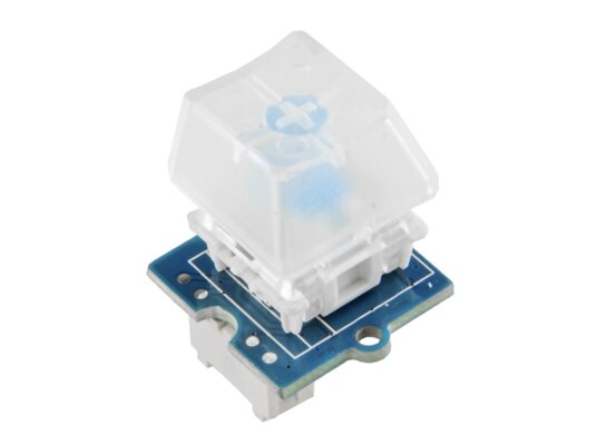
-
Connect Grove - Mech Keypad to port D0 and Grove LED Socket to port D1 of Grove Base
-
Plug XIAO ESP32C3 to Grove Base
-
Connect XIAO ESP32C3 to PC via a USB-C cable
-
Copy the following code into Arduino IDE and upload the code:
This code is generated from ChatGPT
6. Toggle switch LED on and offconst int buttonPin = D0; const int ledPin = D1; bool ledState = false; // current LED state bool lastButtonState = HIGH; bool currentButtonState; void setup() { pinMode(buttonPin, INPUT); pinMode(ledPin, OUTPUT); } void loop() { currentButtonState = digitalRead(buttonPin); // Detect button press (HIGH → LOW transition) if (lastButtonState == HIGH && currentButtonState == LOW) { ledState = !ledState; // toggle LED digitalWrite(ledPin, ledState ? HIGH : LOW); } lastButtonState = currentButtonState; delay(50); // simple debounce }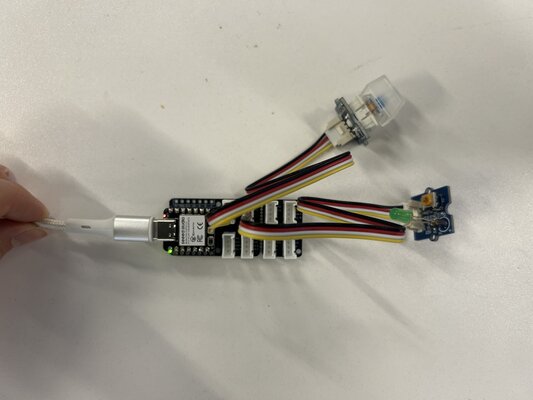
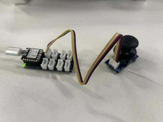
4. Thumb Joystick
-
Prepare the materials needed:
- XIAO ESP32C3
- Grove Base for XIAO
- Grove - Thumb Joystick
Grove - Thumb Joystick
Grove Thumb Joystick uses two approximately 10k potentiometers for the X and Y axes, allowing it to detect movement in two dimensions by producing analog signals.
Specifications:
Item Min Typical Max Unit Working Voltage 4.75 5.0 5.25 V Output Analog Value (X-Coordinate) 206 516 798 \ Output Analog Value (Y-Coordinate) 203 507 797 \ 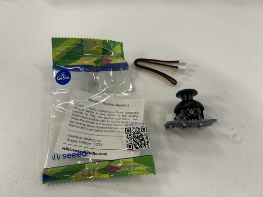
-
Connect Grove - Thumb Joystick to the A0/A1 of Grove Base by using the 4-pin grove cable
-
Plug XIAO ESP32C3 to Grove Base
-
Connect XIAO ESP32C3 to PC via a USB-C cable
-
Copy the following code into Arduino IDE and upload the code:
This code is generated from ChatGPT
/* Thumb Joystick demo for XIAO ESP32C3 Grove Thumb Joystick connected to A0 & A1 */ const int pinX = 2; // A0 → GPIO2 const int pinY = 3; // A1 → GPIO3 void setup() { Serial.begin(115200); // Optional: set ADC resolution (default is 12-bit) analogReadResolution(12); } void loop() { int sensorValue1 = analogRead(pinX); int sensorValue2 = analogRead(pinY); Serial.print("X: "); Serial.print(sensorValue1); Serial.print(" Y: "); Serial.println(sensorValue2); delay(200); } -
When we move the joystick, we can see the X and Y values change in the Serial Monitor.
5. PIR Motion Sensor
-
Prepare the materials needed:
- XIAO ESP32C3
- Grove Base for XIAO
- Grove - PIR Motion Sensor
Grove - PIR Motion Sensor
This sensor is designed to detect movement, typically from human movement.
Features:
- Grove compatible interface
- Adjustable detecting distance
- Adjustable holding time
Specifications:
Item Value Operating Voltage 3V–5V Operating Current(VCC = 3V) 100uA Operating Current(VCC = 5V) 150uA Measuring Range 0.1 - 6m Default detecting distance 3m Holding Time 1 - 25s Working Wave Length 7 - 14um Detecting Angle 120 degrees 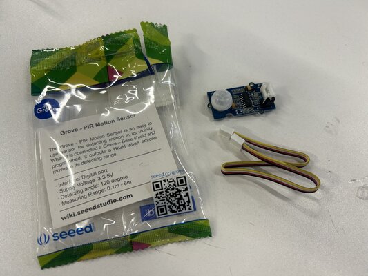
-
Connect Grove - PIR Motion Sensor to port D2 of Grove Base
-
Plug XIAO ESP32C3 to Grove Base
-
Connect XIAO ESP32C3 to PC via a USB-C cable
-
Copy the following code into Arduino IDE and upload the code:
This code is generated from ChatGPT
6. If motion just started -> “🚶 Motion detected!”, if motion just stopped -> “👀 Motion ended”#define PIR_MOTION_SENSOR D2 // 👈 use a Grove digital port int lastState = LOW; void setup() { pinMode(PIR_MOTION_SENSOR, INPUT); Serial.begin(115200); } void loop() { int currentState = digitalRead(PIR_MOTION_SENSOR); if (currentState != lastState) { if (currentState == HIGH) { Serial.println("🚶 Motion detected!"); } else { Serial.println("👀 Motion ended"); } lastState = currentState; } delay(50); }
6. RTC (Real Time Clock)
-
Prepare the materials needed:
- XIAO ESP32C3
- Grove Base for XIAO
- Grove - RTC
Grove - RTC
This module supports I2C and uses R1225 battery to keep accurate time (including leap years) in 12- or 24-hour format up to the year 2100.
Specifications:
Item Value PCB Size 2.0cm*4.0cm Interface 2.0mm pitch pin header IO Structure SCL, SDA, VCC, GND ROHS YES VCC 3.3 ~ 5.5V Logic High Level Input 2.2 ~ VCC+0.3 V Logic Low Level Input -0.3 ~ +0.8 V Battery Voltage 2.0~3.5 V 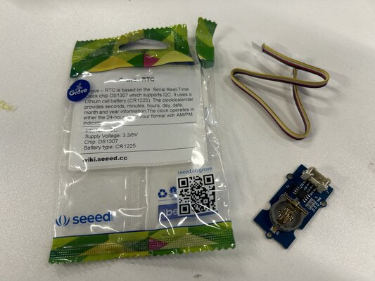
-
Connect Grove - RTC to port I2C of Grove Base
-
Plug XIAO ESP32C3 to Grove Base
-
Connect XIAO ESP32C3 to PC via a USB-C cable
-
Download the RTC Library
-
Open Arduino IDE. Click on
Sketch -> Include Library -> Add .ZIP Library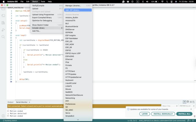
-
Check if the library install correctly. Click on
File -> Examples -> Grove - RTC DS1307 -> SetTimeAndDisplay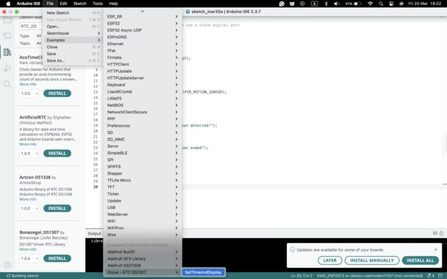
-
Copy the following code into Arduino IDE and upload the code:
This code is generated from ChatGPT
9. In the Serial Monitor, we can see the time, date, and day:#include <Wire.h> #include "DS1307.h" #define SDA_PIN 6 #define SCL_PIN 7 DS1307 rtc; // renamed from "clock" to "rtc" void setup() { Serial.begin(115200); Wire.begin(SDA_PIN, SCL_PIN); rtc.begin(); // Set time once, then comment out rtc.fillByYMD(2026, 3, 20); rtc.fillByHMS(12, 0, 0); rtc.fillDayOfWeek(FRI); rtc.setTime(); } void loop() { printTime(); delay(1000); } void printTime() { rtc.getTime(); Serial.print(rtc.hour, DEC); Serial.print(":"); Serial.print(rtc.minute, DEC); Serial.print(":"); Serial.print(rtc.second, DEC); Serial.print(" "); Serial.print(rtc.month, DEC); Serial.print("/"); Serial.print(rtc.dayOfMonth, DEC); Serial.print("/"); Serial.print(rtc.year + 2000, DEC); Serial.print(" "); switch (rtc.dayOfWeek) { case MON: Serial.print("MON"); break; case TUE: Serial.print("TUE"); break; case WED: Serial.print("WED"); break; case THU: Serial.print("THU"); break; case FRI: Serial.print("FRI"); break; case SAT: Serial.print("SAT"); break; case SUN: Serial.print("SUN"); break; } Serial.println(); }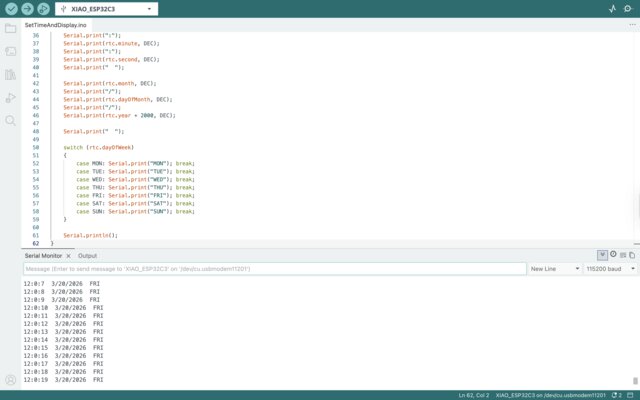
Using My Own PCB
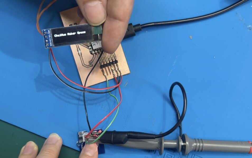
In this experiment, I used the Grove Touch Sensor as the primary input device to detect touch interactions and display the results on an OLED screen.
(Updated on 23 April 2026)
-
Prepare the materials needed:
- XIAO ESP32C3
- Jumper Wires
- OLED display (0.96”, I²C)
- Grove - Touch Sensor
Grove - Touch Sensor:
The Grove Touch Sensor is a capacitive touch module based on the TTP223-BA6 chipset. It detects touch input by measuring changes in capacitance when a finger comes close to or touches the sensor surface.
Unlike mechanical buttons, this sensor has no moving parts, which makes it more durable and reliable for long-term use. It is also highly sensitive and can detect even light touches.
How It Works:
- The sensor continuously monitors the capacitance on its electrode.
- When a finger approaches, the capacitance increases.
- The onboard chip processes this change and outputs a digital signal:
- HIGH (1) -> Touch detected
- LOW (0) -> No touch
Specifications:
Item Value Operating Voltage 2.0V - 5.5V Operating Current(Vcc=3V) 1.5 - 3.0μA Operating Current(VDD=3V) 3.5 - 7.0μA Output Response Time 60 - 220ms Used Chipset TTP223-BA6 Interface Digital Port -
Circuit Connections:
- Connect the Grove Touch Sensor signal pin to GPIO 8
- Connect the OLED display: SDA -> GPIO 6 and SCL -> GPIO 7
-
Power Connection:
Connect the XIAO ESP32C3 to your computer using a USB-C cable.
-
Upload the Code:
Copy and upload the following code using the Arduino IDE:
(This code is generated from ChatGPT)
#include <Wire.h> #include <Adafruit_GFX.h> #include <Adafruit_SSD1306.h> #define SCREEN_WIDTH 128 #define SCREEN_HEIGHT 64 #define OLED_RESET -1 Adafruit_SSD1306 display(SCREEN_WIDTH, SCREEN_HEIGHT, &Wire, OLED_RESET); // Touch Sensor Pin (Using GPIO 8 as requested) const int touchPin = 8; int counter = 0; bool lastTouchState = false; void setup() { Serial.begin(115200); // Initialize I2C with your specific pins (SDA=6, SCL=7) Wire.begin(6, 7); // Initialize Touch Sensor pinMode(touchPin, INPUT); if(!display.begin(SSD1306_SWITCHCAPVCC, 0x3C)) { Serial.println(F("OLED failed")); for(;;); } // Initial Screen Setup display.clearDisplay(); display.setTextColor(SSD1306_WHITE); display.setTextSize(1); display.setCursor(20, 20); display.print("Touch to Start"); display.display(); Serial.println("Touch Sensor Initialized on GPIO 8"); } void loop() { // Read sensor (TTP223 is HIGH when touched) bool currentTouchState = digitalRead(touchPin); // Check for the moment the sensor is FIRST touched if (currentTouchState == HIGH && lastTouchState == LOW) { counter++; if (counter > 10) { counter = 1; } Serial.print("Touch! New Count: "); Serial.println(counter); updateDisplay(); // Simple debounce to prevent rapid-fire counting delay(150); } lastTouchState = currentTouchState; delay(10); // Stability delay } void updateDisplay() { display.clearDisplay(); // Header display.setTextSize(1); display.setCursor(35, 0); display.print("TOUCH COUNT"); display.drawFastHLine(0, 12, 128, SSD1306_WHITE); // Big Number display.setTextSize(4); if (counter < 10) { display.setCursor(52, 25); } else { display.setCursor(40, 25); } display.print(counter); display.display(); } -
Expected Output:
Each time the sensor is touched:
- The counter increases by 1
- The value is displayed on the OLED
- After reaching 10, the counter resets back to 1 and repeats
This behavior is achieved by detecting the rising edge of the touch signal (transition from LOW to HIGH), ensuring that each touch is counted only once.