Week 7: Computer-Controlled Machining
MAKING BIG THINGS.
Week 7 Assignment:
-
Group Assignment
- Do your lab’s safety training
- Test runout, alignment, fixturing, speeds, feeds, materials, and toolpaths for your machine
-
Individual Assignment
- Make (design+mill+assemble) something big (~meter-scale)
-
Extra credits:
- Don’t use fasteners or glue
- Include curved surfaces
- Use three-axis toolpaths
GROUP ASSIGNMENT
Chai Huo Week 7 - Group Assignment
Our group will meet in April to complete the group assignment.
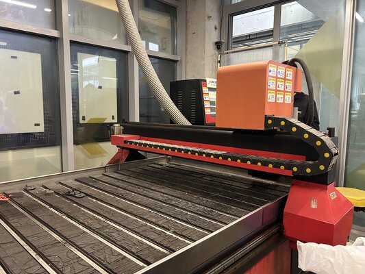
CNC Milling Machine Information
TIANCHENG XINLI Wood CNC engraving machine TC1325B
The Shenzhen Tiancheng Xinli CNC wood carving machine is a CNC device designed for woodworking, capable of automated carving, cutting, and milling. It offers high accuracy and efficiency, making it ideal for furniture production, woodcraft design, and panel processing.
Working Area: 1300mm (X) x 2500mm (Y) x 200mm+ (Z)
Safety Training
- Personal Protective Equipment (PPE)
Eye Protection: Safety glasses are mandatory. High-speed bits can shatter, and wood chips fly at high velocities.
**Hearing Protection:** The spindle and vacuum pump can exceed 85dB; earplugs or earmuffs are highly recommended.

**Respiratory Protection:** MDF contains glues and resins. You must wear a dust mask (N95 or better) and ensure the dust collector is running.

**No Loose Clothing:** Remove jewelry, lanyards, and watches. Tie back long hair and roll up long sleeves to prevent entanglement in the spindle or rack-and-pinion tracks.
-
Machine Pre-Check
Path Clearance: Manually “Jog” the machine to ensure the spindle won’t hit any clamps or the machine frame during its program.
Tool Tightness: Ensure the collet is tightened correctly. A loose bit at 24,000 RPM is a lethal projectile.
E-Stop Location: Know exactly where the red Emergency Stop button is. Keep your hand near it during the first 30 seconds of a new program.
-
Environmental & Material Safety
Fire Hazard: MDF dust is flammable. If your feed rate is too slow (dwelling too long), the friction can cause the wood to smoke or catch fire.
Note: 5000 mm/min speed is good; it keeps the tool moving fast enough to dissipate heat.
Workpiece Security: Never hold the material by hand. Since we used 18mm MDF, we need to ensure clamps are incredibly tight, as the lateral force of an 8mm bit is very strong.
Housekeeping: Keep the floor around the machine clear of off-cuts to prevent tripping while the machine is in motion.
-
Operational “Golden Rules”
Never Leave Unattended: Stay with the machine for the entire duration of the cut. Most CNC accidents happen when the operator “just steps away for a minute.”
The “One-Hand” Rule: When the machine is running, keep your hands away from the table. If you must point at something, use a stick or a tool, never your finger.
Post-Cut Safety: Wait for the spindle to come to a complete stop before reaching in to remove your side table parts.
INDIVIDUAL ASSIGNMENT
Since the actual printing will take place in April, I completed the design this week and tested a small-scale print using a 3D printer.
Note
Initially, I planned to use Autodesk Fusion or SOLIDWORKS for CAM. However, I could not access my student account for Fusion, and SolidWorks does not run on my MacBook.
In this project, I will use OnShape to design the 3D model.
Information (CAD & CAM)
-
CAD (Computer Aided Design) - computer programs or online applications (apps) to design the object
-
CAM (Computer Aided Manufacturing) - a software that converts a digital design into instructions for machines that manufacture parts
-
Machine Fabrication - a machine executes the instructions
Searching for Inspiration - I have a sofa and a small table at home, but the table is too short. Bending down too much causes my back to hurt, so I decided to make a tabletop that would allow me to work on the sofa without straining my back.
Then I found these on Pinterest:
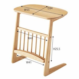 Source: pinterest.com
For the second idea, I want to make a side table to put the Wi-Fi router on:
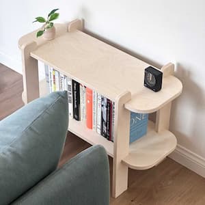 Source: pinterest.com
Designing CAD model on OnShape
Note
I had some difficulty designing the joints because this week’s group assignment has not yet been completed. As a result, I did not know the design rules, the wood thickness, or the radius of the end mill (tool size). For now, I will refer to last year’s group assignmentas a reference, which used 18 mm thick high-density wood and an 8 mm end mill radius.
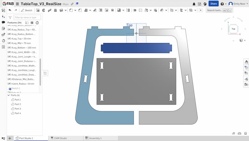
Model 1 - Table Top
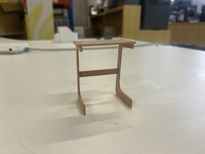
At first, I designed the prototype/miniature size so it could be printed using a 3D printer.
-
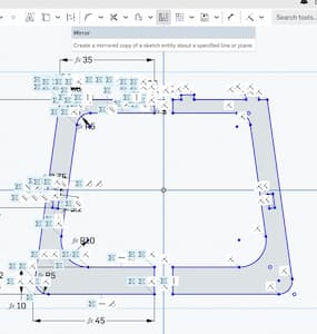
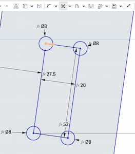
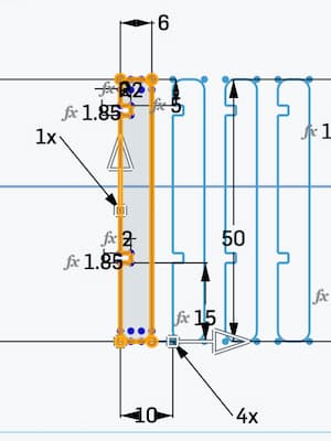
Designing the table leg
I created a joint on the top part and a joint hole in the middle of the leg. I made the bottom part thicker and also created a larger base at the bottom so that it would be more stable.
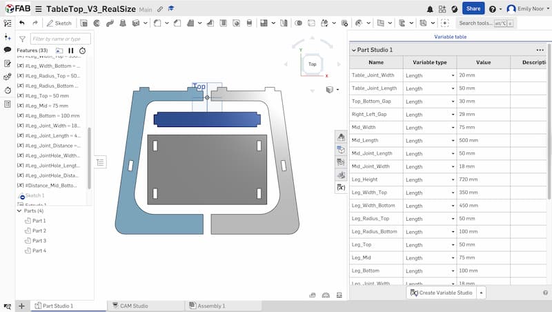
Then I set up the parametric design as shown below:
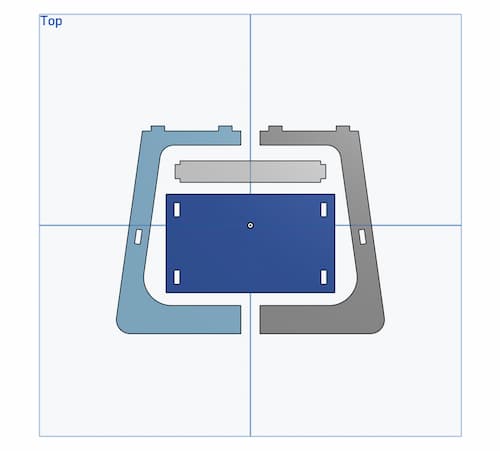
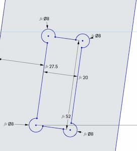
After that, I mirrored the leg so that I had two legs:
-
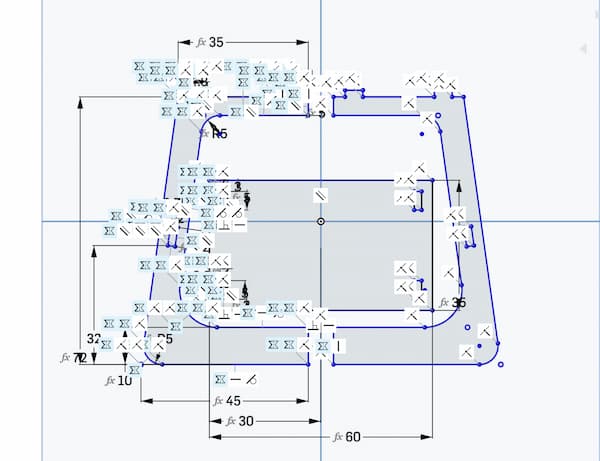
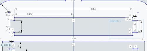
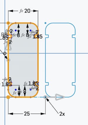
Designing the table top
Next, I designed the tabletop and created the parametric design:
I created two joint holes on the left side:
Then I mirrored them to the right side:
-
Designing the middle support
The last part is the middle support, which acts as a central structure to make the table more stable. This is the parametric design:
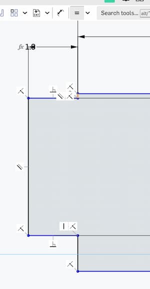
I created three rectangles: one for the main part and two for the joints on each side. Then I deleted the redundant line in the middle using the Trim tool.
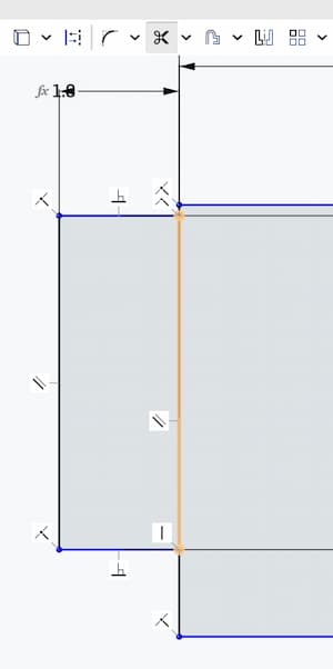
Next, I used the Equal constraint so that the lines on the left and right sides of the joint have the same length.
This is the final part:
-
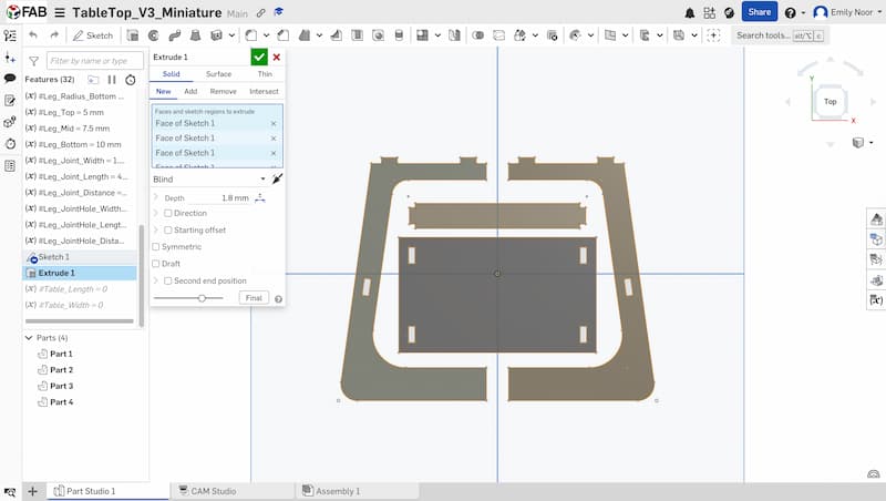
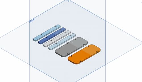
Extruding the parts
I extruded all of the parts and added a depth of 1.8 mm. The miniature model is 10× smaller than the real size.
-
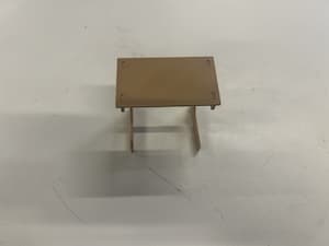
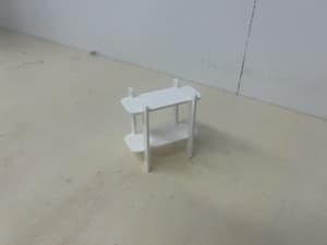
3D printing
Finally, I exported the model as an STL file and printed it using a 3D printer.
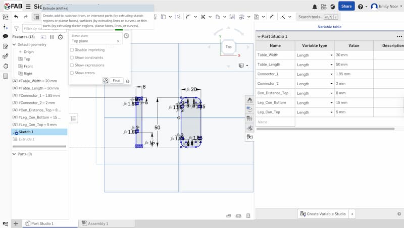
Adjusting the size to the real size
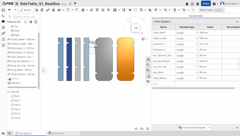
After testing the miniature model, I adjusted the design to the real size. I scaled all of the dimensions to be 10× larger than the miniature model.
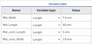
In this step, the parametric design was very helpful. I only needed to change the parameter values in the table, and the whole model automatically updated to the new size.
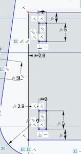
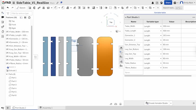
Adding T-Bone / Dog-Bone for the joints
Because CNC milling machines cannot produce perfect right internal corners, it is important to add T-Bone or Dog-Bone fillets when designing joints. These shapes create extra space in the inner corners so that the parts can fit together properly.
T-Bone / Dog-Bone

T-BONE: A T-bone adds a circular cut directly aligned with one axis, forming a shape like the letter “T”.

DOG-BONE: A dog-bone adds a small circular cut at the inside corner, extending diagonally outward.
For this project, I will use Dog-Bone joints.
I first added Center Point Circles on each side of the joint holes.
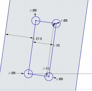
Then I used the Trim tool to remove the redundant lines in the middle.
Here is the result after trimming:
Finally, I added the Dog-Bone features on each side of the joint holes on the left side and then mirrored them to the right side.
Note
Some of the joints may require adjustment before CNC milling.
OnShape Files (Model 1 - Table Top)
Download the 3D model:
-
STL File - Table Top Miniature or open it with the OnShape link - Table Top Miniature
-
STL File - Table Top Real Size or open it with the OnShape link - Table Top Real Size
Model 2 - Side Table
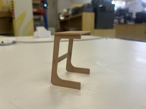
I followed almost the same steps as in Model 1 – Top Table.
First, I created the tabletop and the table leg, and then set up the parametric design.
I used the Linear Pattern tool to duplicate the table leg into 4 pieces:
I also duplicated the tabletop into 2 pieces:
Here is the result:
Then I printed the model using a 3D printer:
Next, I adjusted the design to the real size. I scaled all of the dimensions to be 10× larger than the miniature model.
Finally, I added the Dog-Bone features to the joints.
Note
Some of the joints may require adjustment before CNC milling.
Download the 3D model:
-
STL File - Side Table Miniature or open it with the OnShape link - Side Table Miniature
-
STL File - Side Table Real Size or open it with the OnShape link - Side Table Real Size
(15 April 2026)
I decided to use CNC milling to produce Model 2 – Side Table. The main reason is that I originally wanted to make a tabletop for use at home. However, since I will be leaving Shenzhen in two months, I thought it would be better to make a side table for my friend, as she needs one.
For aesthetic reasons, I wanted the dog-bone joints to be more subtle. To achieve this, I used a Dog-Bone Custom Feature made by Hendrik Kueck
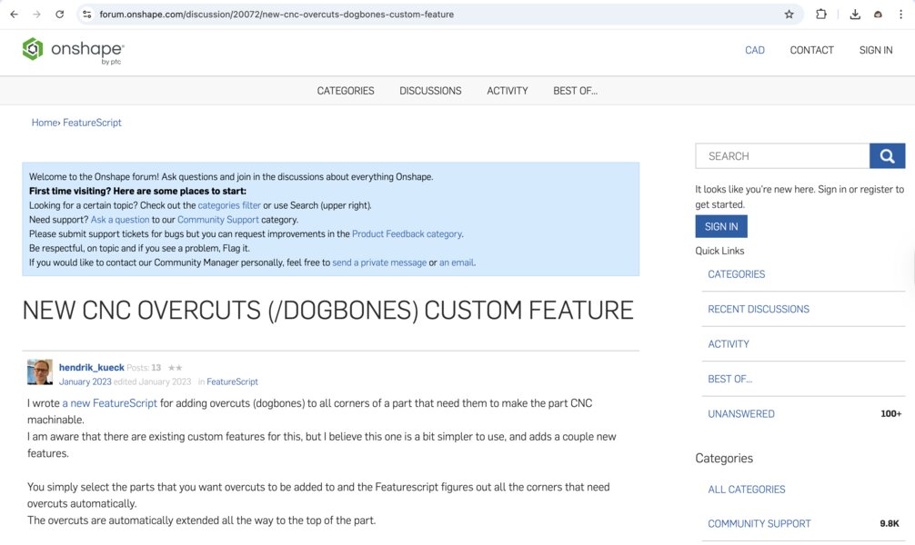
I opened the link and clicked “(+) Custom Features” to add the tool to my toolbar.
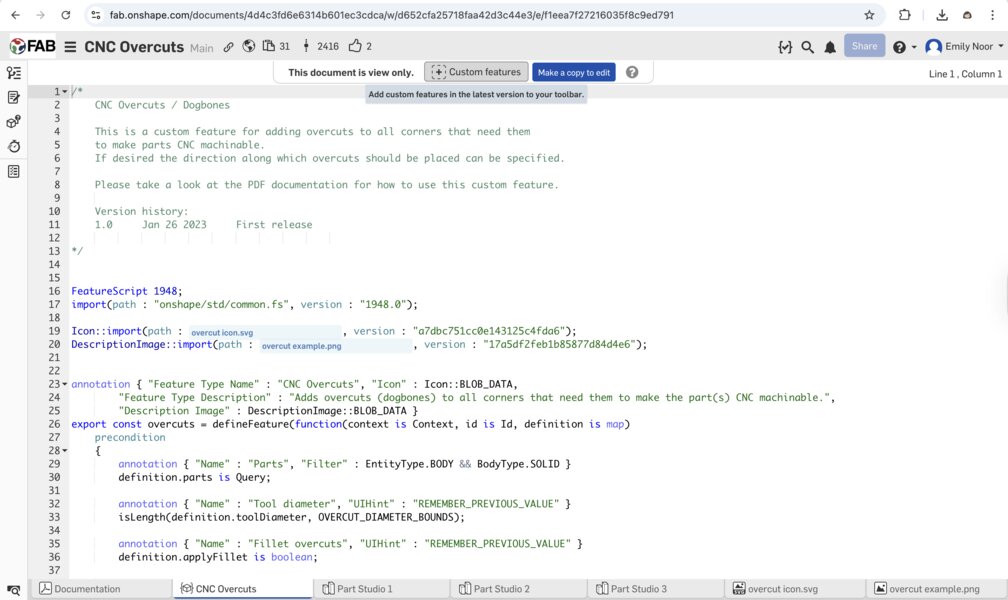
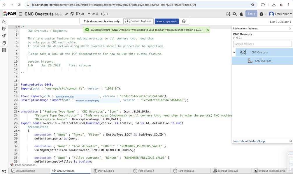
Then, I searched for the custom feature called “CNC Overcuts”
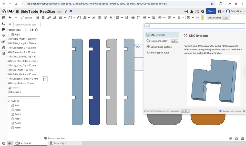
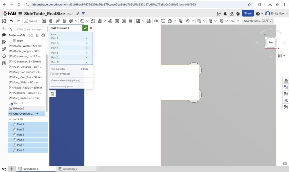
Next, I applied the “CNC Overcuts” feature to all of my joints:
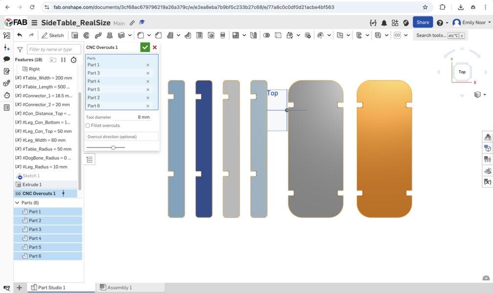
Here is a clearer view of the result:
Milling Process
Generating G-Code with MasterCam X6
After exporting your design as a DXF file, we need convert it into G-Code (.NC) using MasterCam X6.
-
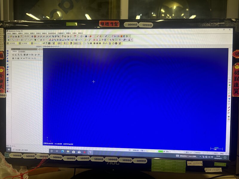
Launch MasterCam X6: Open the software to reach the main workspace.
-
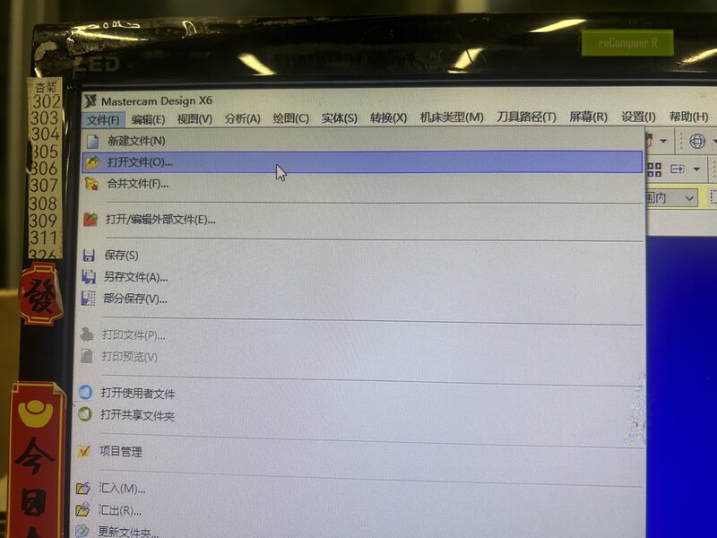
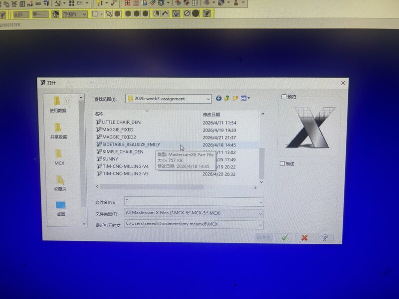
Import your Design: Go to File (文件 F) > Open (打开文件 O) and select your DXF file.
Your geometry should now appear in the workspace.
-
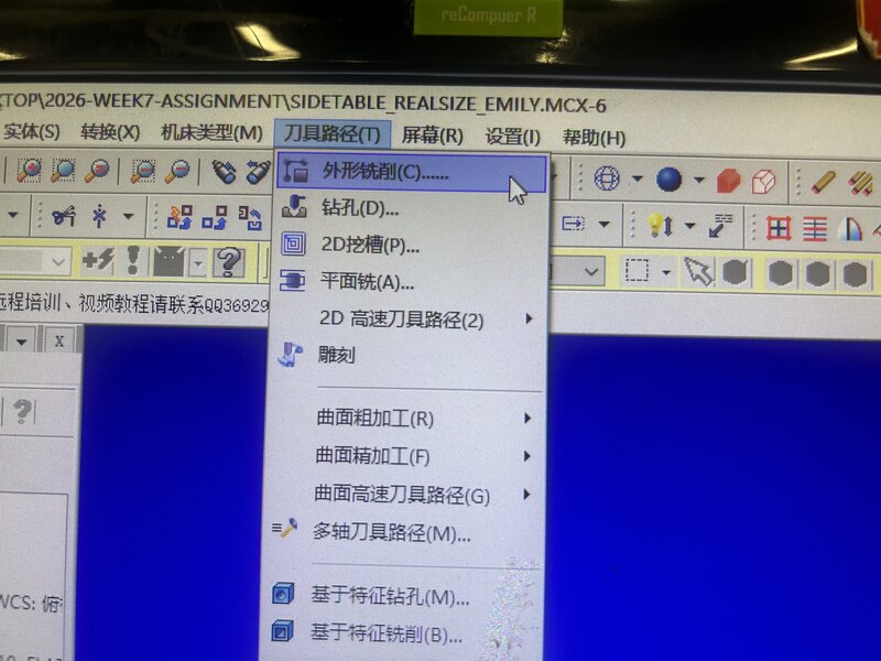
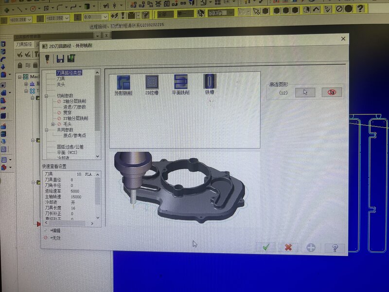
Define the Toolpath:
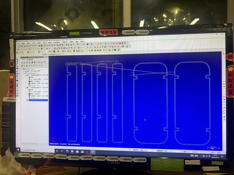
Navigate to Toolpaths (刀具路径 T) and select Contour (外形铣削 C).
In the chaining sidebar, select the Window icon (the three-circle logo) to select your geometry.
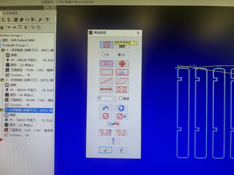
Click and drag to select all pieces,
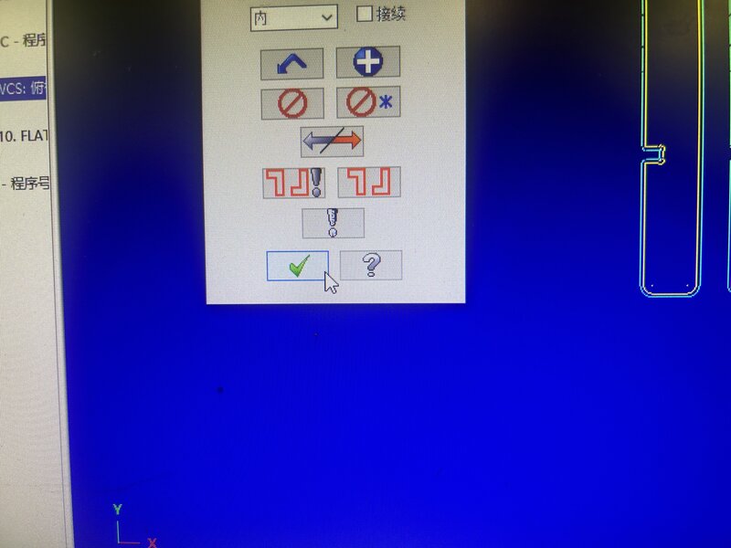
then click the OK (Checkmark) button to confirm.
-
Configure Cutting Parameters:
The 2D Toolpath - Contour window will appear.
Select Cutting Parameters (切削参数).
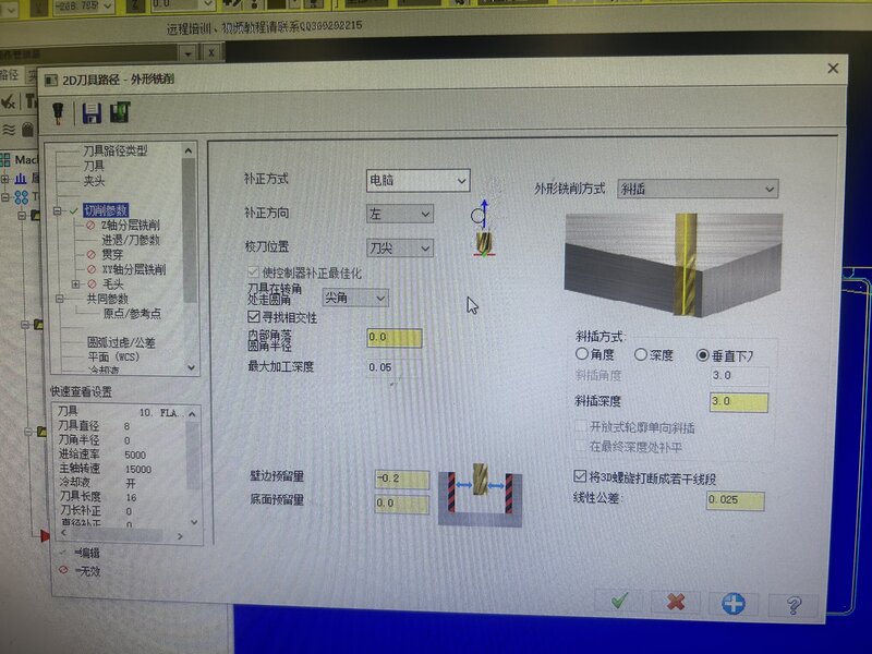
Compensation Direction: Choose between Left (左) or Right (右).
Left: The tool follows the outside of the line (Blue line).
Right: The tool follows the inside of the line (Yellow line).
I chose Left (左) with 3 mm depth of cut per pass.
-
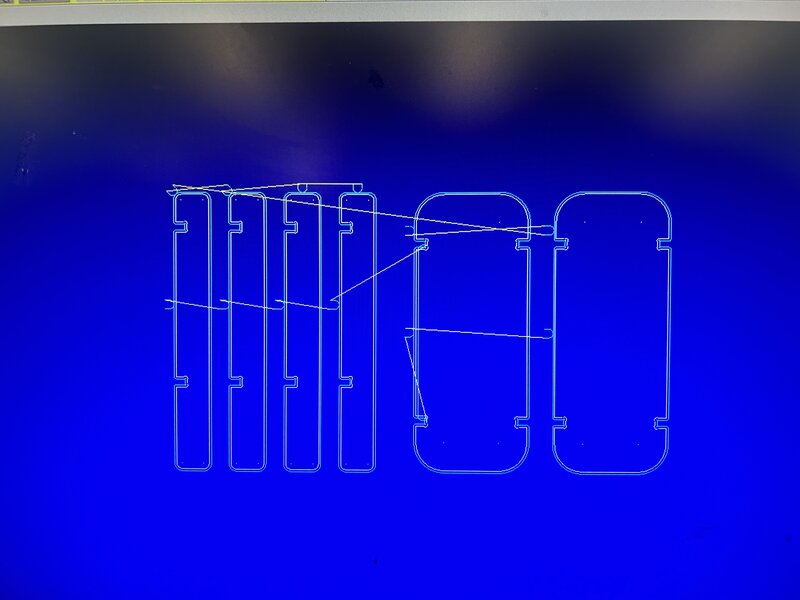
Simulate and Verify:
To preview the milling path, select your operation (e.g., 3-外形铣削)
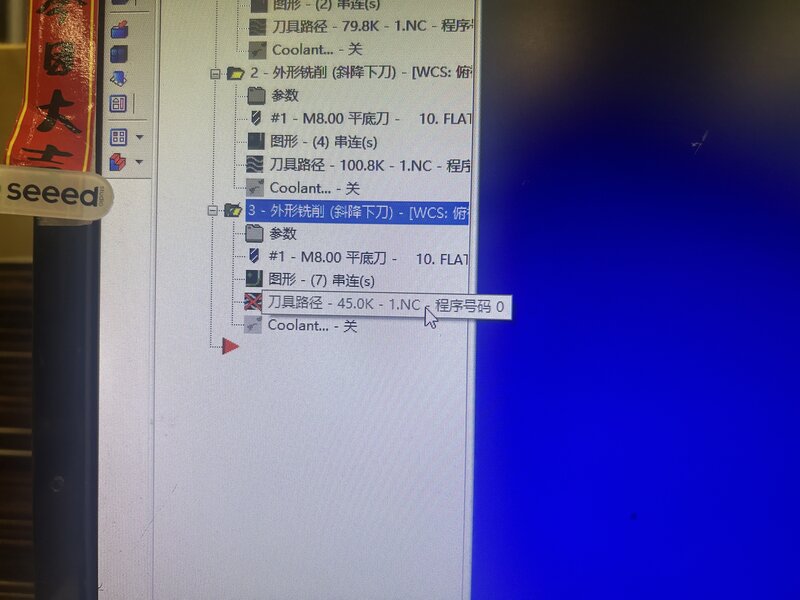
and click the Verify/Play icon.
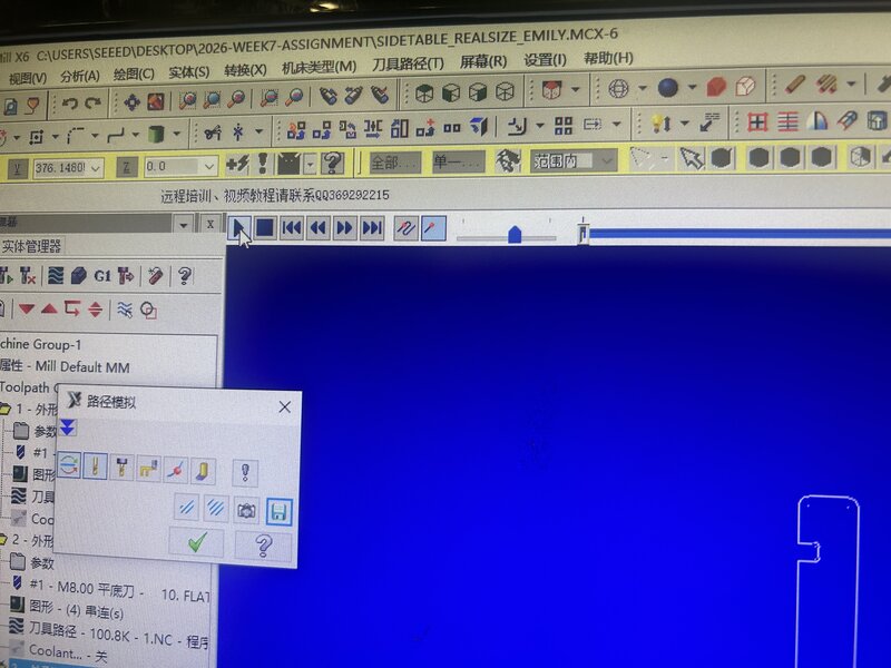
Review the animation to ensure the lead-in, lead-out, and depths are correct.
-
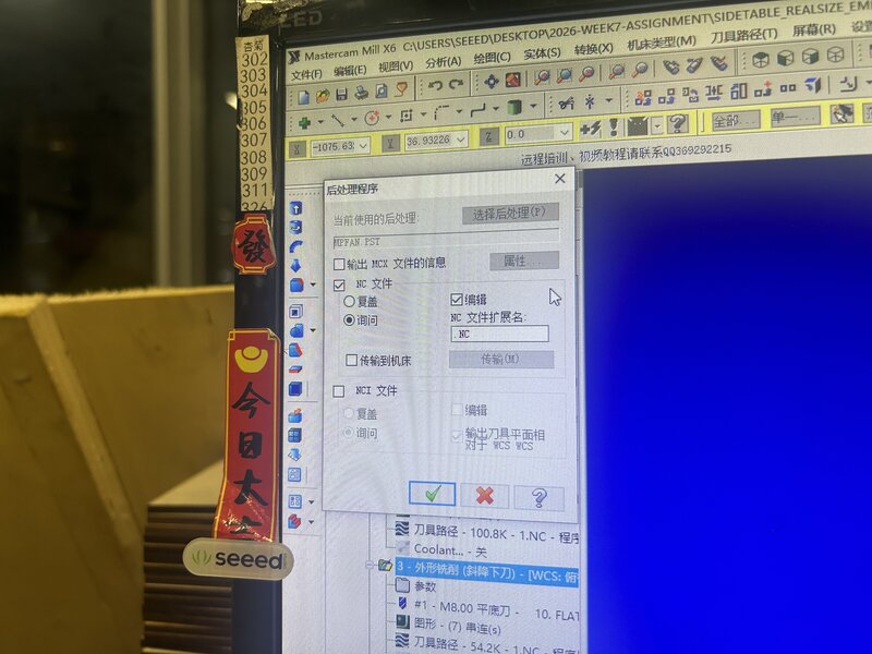
Export G-Code:
Click the G1 button to post-process the file.
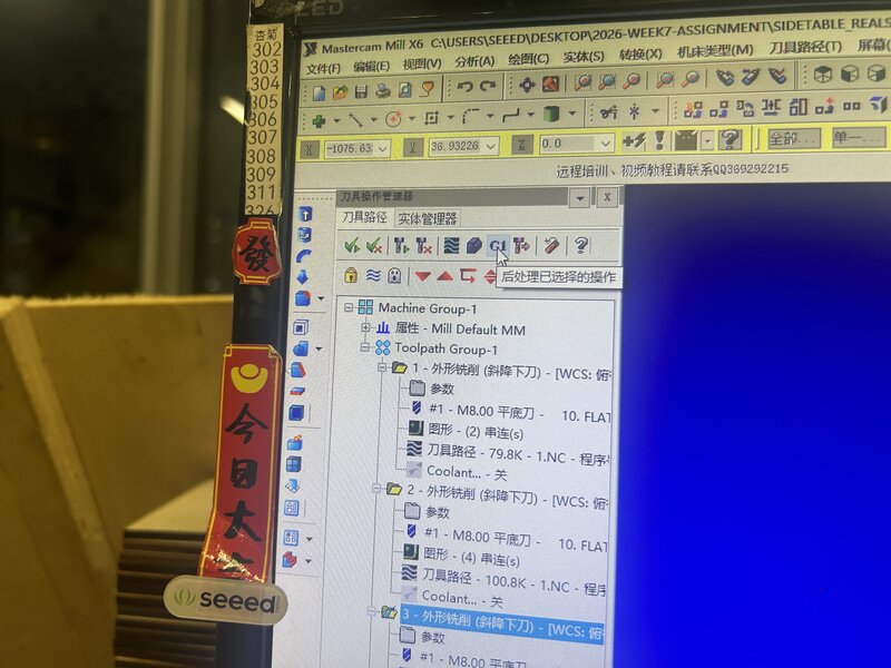
Confirm the settings in the pop-up window and click the OK (Checkmark) to save your .NC file.
G-Code Conversion
The G-code generated in MasterCam X6 must undergo a conversion process to ensure it is fully compatible with our specific CNC milling machine. This conversion step can be done with the assistance of AI tools.
CNC Milling
-
Physical Machine Setup
Before jumping into the CNC software, the physical machine must be prepared:
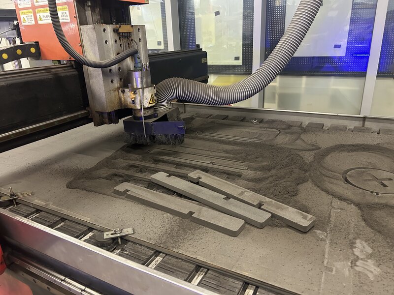
Clear the workspace: Clean the machine bed thoroughly, removing any dust, debris, or leftover materials.
Load the stock material: Carefully place the material on the bed. For this project, we used black MDF. Because large MDF sheets are heavy, it requires multiple people to lift and position the board safely.

Material Note
We used 18mm Black MDF, a high-density engineered wood. While its weight requires a team effort to load, its lack of grain makes it incredibly stable for CNC milling, allowing for precise dimensions and a smooth finish that doesn’t require heavy sanding.
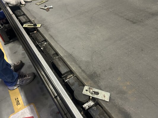
Secure the material: Attach clamps to all sides of the MDF to ensure the stock remains firmly in place during the milling process.
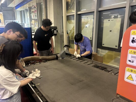
Final check: Double-check the clamps. We can now rest assured that the material is completely immobilized.
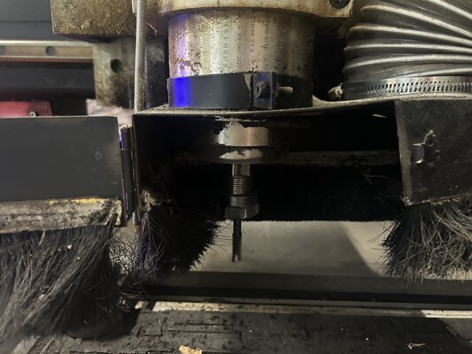
Tool Diameter: The end milling tool used is an 8mm diameter, 2-flute, center-cutting end mill.
Next, we move on to the CNC milling machine software:
-
Digital Loading
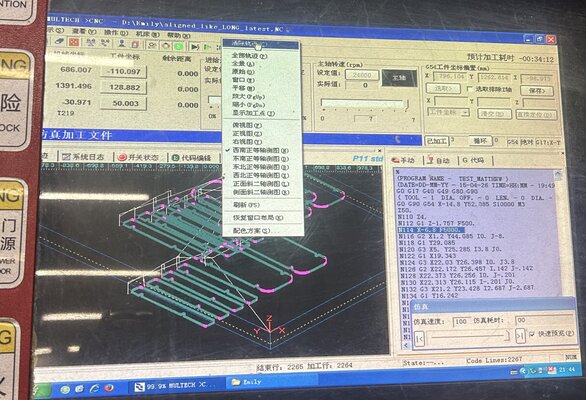
The digital process begins by loading the G-code file (a text document filled with precise coordinates starting with G, X, Y, and Z). This file, created in the CAD/CAM software, contains every single movement the machine needs to make. The operator opens the file, which then populates in the right-hand code window.
-
Tool Positioning (Jogging)
Before cutting, the operator must physically move the machine’s spindle to the correct starting position over the material.
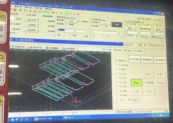
The “Jog” (Manual Movement): Using the directional buttons shown in the image above, the operator moves the spindle along the X, Y, and Z axes.
-
Defining the Origin (Zeroing)
While the machine knows its absolute “home” position, it doesn’t automatically know where the stock material is placed on the bed.
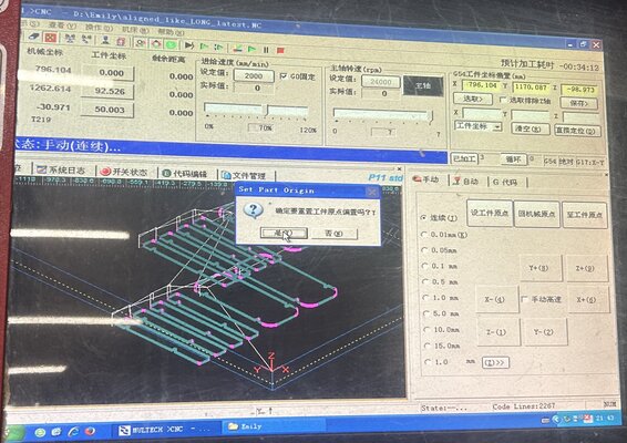
Once the cutting tool is precisely touching the desired starting corner of the material, the operator clicks “Set Part Origin.” The image above shows the confirmation pop-up: “Confirm setting part origin?” This registers that exact physical spot as the (0, 0, 0) coordinate for the G-code program.
-
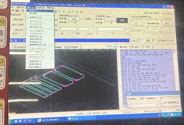
Visual Verification (Simulation)
To prevent breaking a tool or crashing the spindle into a clamp, the operator runs a digital simulation before making any actual cuts.
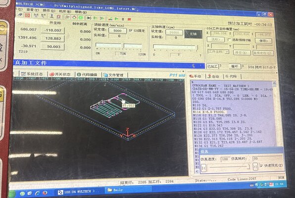
Trace View: The image above shows the “Trace” window. It draws the projected toolpath using blue and pink lines to help you visualize the final shape.
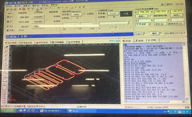
Simulation Mode: n the image above, the operator is running the code in “Simulate” mode. The software digitally “pre-cuts” the part to check for errors and calculates the estimated machining time (estimated at 20 minutes and 55 seconds).
-
Live Execution
Finally, once everything is verified, the operator switches to “Auto” mode and hits Start.
Spindle Control: The software turns on the spindle (spinning it up to 24,000 RPM) and begins following the lines of G-code one by one.
Feed Rate: The machine begins following the G-code at a Feed Rate of 5000 mm/min, moving the tool through the MDF to execute the design.
Machining Parameters
-
Tool: 8mm 2-flute center-cutting end mill
-
Spindle Speed: up to 24,000 RPM
-
Feed Rate: 5,000 mm/min
-
The milling process preview:
Final Assembly
“Assembly Footage
I was so excited to assemble the side table that I forgot to take a video of the actual assembly process!
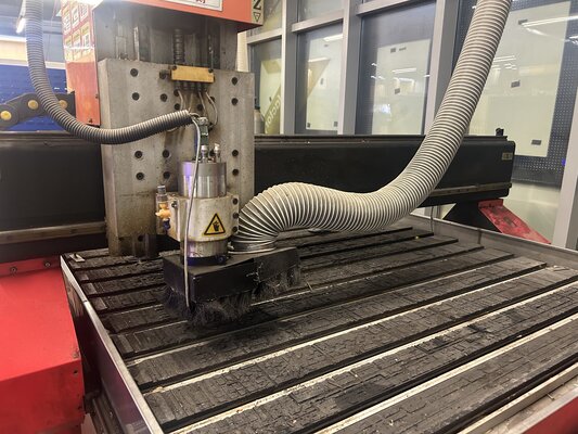
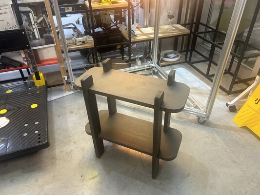
The image below shows the machine immediately after finishing the milling process:
The final assembly was quite straightforward. The design consists of connecting the four legs to the two horizontal surfaces (the top and the shelf).
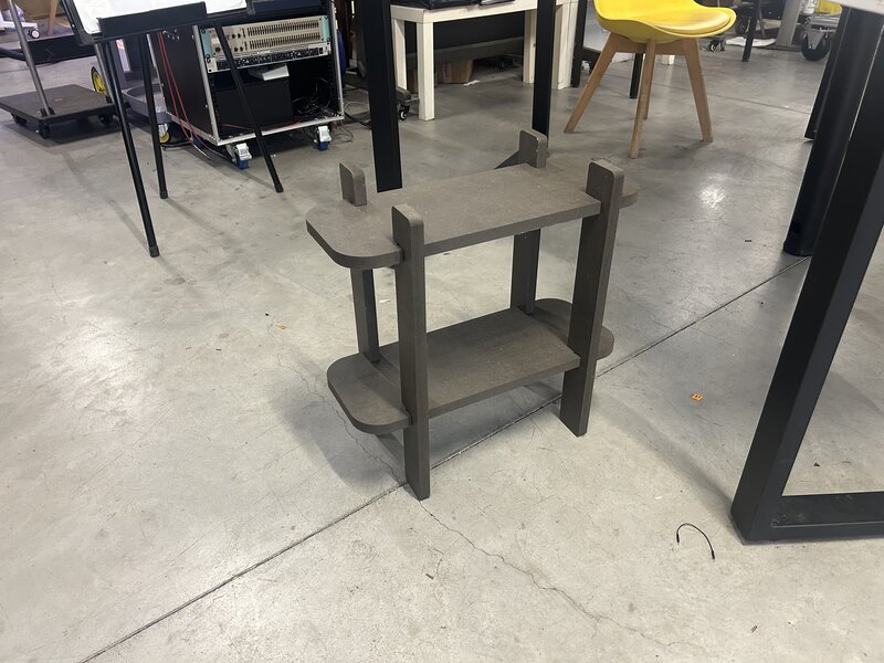
Here is a photo of me with the completed side table:
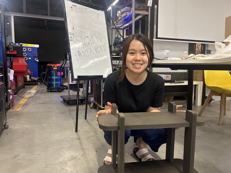
Stability Issue: The table is wobbly…
During the test fit, I discovered the table was wobbly. I made the joints too large; while the MDF board is 18mm thick, I designed the joint slots to be 18.5mm. That 0.5mm difference created too much “play” in the joints. To fix this and secure the structure, I used wood glue for all the connections.
The wood glue used for the fix:
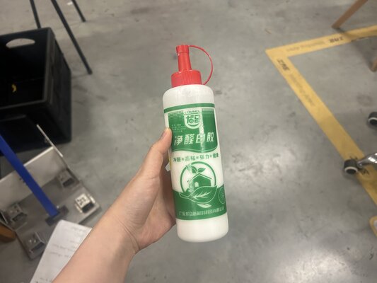
After applying the glue and letting it set, the table is now solid and no longer wobbles! :)
G-Code File