About My Project
My final project is a low cost pan-tilt turret, with a wide range of applications.
Goals
- Extremely low cost
- Fully 3d printed
- Easy to use
- Easily soldered circuits
- Easy Programming
- Easy to modify
- I learn something from this
Extremely low cost
Fully 3d printed
Easy to use
Easily soldered circuits
Easy Programming
Easy to modify
I learn something from this
Weekly Assignments
Throughout Fab Academy, I utilized my weekly assignments to step-by-step develop the components of this final project. Below is a log of the specific weeks that contributed to this pan-tilt turret:
- Week 2: Computer-Aided Design: Designed the initial 3D assembly and kinematics for the turret base and head.
- Week 4: Embedded Programming: Prototyped the basics of stepper motor control and web server camera streaming.
- Week 5: 3D Scanning and Printing: Printed a print-in-place miniature version of the moving turret and redesigned the camera head layout.
- Week 8: Electronics Production: Milled the first-pass PCBs for the stepper drivers and custom battery breakout boards.
- Week 11: Networking and Communications: Developed the custom frequency packet protocol utilized between the wireless USB dongle and the turret.
- Week 13: Molding and Casting: Designed the mold and casted the translucent blackout window for the front camera bay.
- Week 14: Interface and Application Programming: Wrote the frontend web interface with an interactive joystick for controlling the turret's rotation.
- Week 15: System Integration: Integrated the internal gearing into the turret base, manufactured the large outer shell, and revised the main PCB layout.
- Week 17: Applications and Implications: Established the project requirements, constraints, and documented the bill of materials.
- Week 18: Invention, Intellectual Property, and Income: Defined the project's open-source dissemination strategy and selected the MIT license.
- Week 19: Project Development: Tracked implementation progress and outlined the final steps required for project completion.
Electronics
The electronics for this project were both the funnest part and the most challenging
Initial Electronics & Software Design
My initial design involved a complex ecosystem of 4 custom boards (Battery, Microcontroller, Stepper Driver, USB-C) distrubuting functions between them. While pretty cool, especially the stepper driver board, It was just too much to work well, and especially as the microcontroller used (ESP32-C3) required alot of power, resulting in a low amount of power actually going to the stepper motors.
Click here to read the full breakdown of the old System
Final Board Design
The final board was an almost complete redesign of the old one. The things kept were the stepper drivers, where I found the drv8835 to be a really good, cheap chip. It also keeps wireless functionalitiy, but using a completely different chip, the CH572D.
CH572D is goated
Deciding to switch microcontrollers so far in was a major delay, but I think it was worth it. Simply put, the chip is 20 cents for bluetooth, 10x cheaper than the old chip (especially post price raises as a result to tariffs). However, the chip is around 10x worst in some aspects, including the community/developer support and flash/ram (1/8th the flash, 1/33 the ram). While it might be a pretty big downgrade in some areas, the price alone makes this chip the most coolest little thing I've ever used in my life (17 as of writing this)
Instead of a 4 board design, I consolidated the boards here, and used a pre-made USB-C charging board from amazon. This finally gave me the power I needed for the steppers, and combined with redefining parts of the 3d design, finally gave me the power to move such heavy parts on such cheap hardware
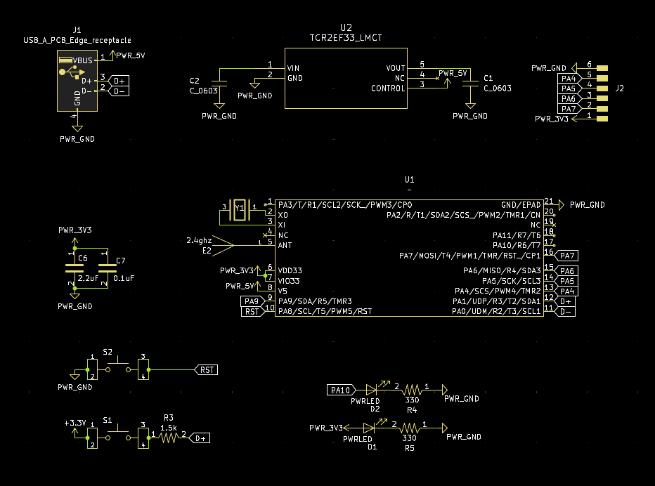
Schematic(s)
These are all on one board, im just doing 3 images for better detailed descriptions per
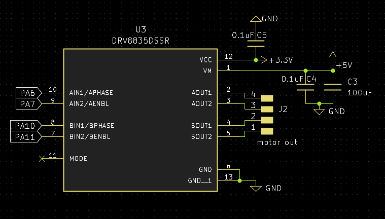 The driver is kinda my standard by this point. its just such a goated chip, as its cheap, easy to use (I guess its not like i2c but still), and works really well for my use cases. I've used this for regulator motors too, with this exact schematic. Only bad thing I can say about this, and about the driver really is that on the final boards im using I forgot to add a spot for a second capacitor, and instead stacked 2 which worked and saved space, so could be a cool trick to pull off in the future
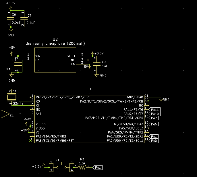 I've already talked about how much I love the ch572, but heres even more proof. None of that fancy bluetooth antenna matching pi networking stuff. This chip is so goated that I just put the antenna pin into a standard antenna design from like TI or someone, and it works amazingly. also that voltage regulator (the one called "the really cheap one (200mah)) is another standard part for my projects, as I have like 3 entirely different voltage regulators, but all with the same requirement of load capacitors, and they each have different current maxes, at 200, 300, and 600ma. Reason im using the 200 hear is because its just the cheapest. DRV8835 doesn't require high power on its logic pin, but idk i guess be aware if your using this design and want to use other stuff
the 200mah one is linked here The 300mah one is linked here The 600mah one is linked here They're all 3.3v sot23-5 here, but im pretty certain theres different versions of all 3 for regulating voltages 1.8 to 5 (max voltage on all 3 is just under 6v btw be aware, I power through usbc/5v from the battery board)
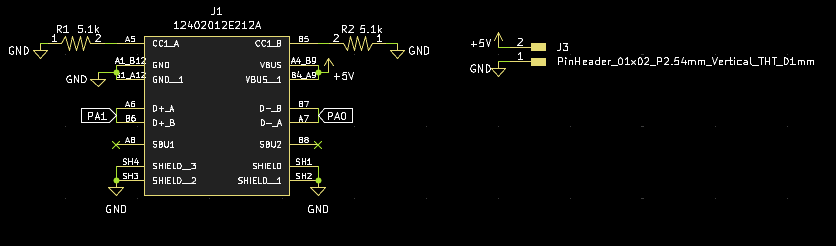 Idk simple usbc schematic. I guess its kinda kinda cool since thats a custom symbol there, just a modification of the original to put the stuff near eachother, instead of having the pins all on the left in random orders that gave off bad vibes (and bad looks)
Layout
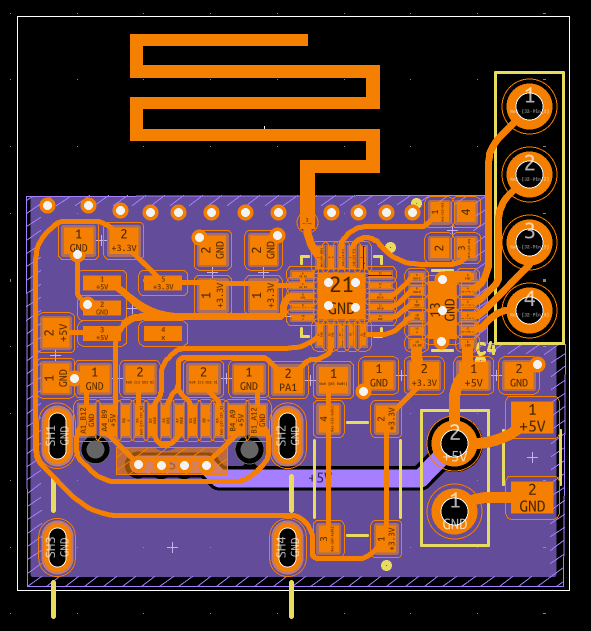 I think the curves look pretty cool. Im no PCB designer (although I really want to do that as my job in the future), so here is my creative mind shining through. Far as I can tell (if your a master pcb designer and see issues anywhere pls pls pls message me), routing like this shouldn't cause any issues, and might even improve stuff. I guess the cool thing here is that PCB antenna, which is actually my first use of that type (I started with a chip antenna, then the exact pcb antenna of the dev board, and now this). groundings pretty important for these kinda things, so ground plane on the bottom, with only one trace going through it, and no traces near the antenna. Stiching vias all over as a wall near the antenna trace, and (my best attempt) at keeping the area near the antenna clear of components. I will say that this is my first rounded type board design, and I think i've gotten better at making it looks good since then. also I should note here now that I have updated the design, as I forgot a capacitor for the drv8835on the first production run
Ordering
quick little aside here, as im using a pcb antenna and not a chip antenna, I had(? conventional wisdom) to use a ENIG surface finish. This either costs more money, or causes you(me) to look for a supplier with cheap ENIG. oshpark, a lowkey goated american pcb fab, offers really high priced boards, but their pricing is dimension based, so for a small board like this, it cost be 3 dollars (free shipping) to get 3 ENIG dual layer boards. They got here faster than JLCPCB(with cheapest shipping of course).
Soldering
Having good soldering skills is pretty important when you(me) don't wanna spend a bunch of money on assembly. I've tried basically every way of soldering at this point: with an iron, with an oven, with a hotplate, and with hot air. I've found hot air to be so much better than the others (of course using an iron is just simplier for simplier things), but for SMD assembly, hot air is the way to go. If your looking into it for the first time, please dont get a airgun/hairdryer looking thing, get those really chunky ones you hold like a pencil. I tried using those, and they just spit out such an absurd amount of heat, and would blow away the components if I used a nozzle. my personal one is this one, but really just read the reviews for using it how you want to use it for stuff like this.
Programming
The CH572D is really funky in programming it. Theres 2 main methods I've seen. The company behind it directly supports Mounriver Studio, which is essentially just vscode. It uses C, it has extensive (chinese) documentation/examples, and is able to use the advanced bluetooth functions (you gotta be really smart though their examples for them kinda suck). The other method is the CH32FUN project. I think the best way to compare the two, is that their webpage(/github) has mounriver opening to chinese, and ch32fun opening to a really detailed (english) explanation of how the dev environment works. For reasons mostly involving not speaking chinese, and prefering open source stuff, I am using ch32fun for this. I have since used mounriver for a electric vehicle im making for science olympiad, as ch32fun doesn't support PWM for the specific chip I was using (CH592).
ch32fun
This a open source developmentenvironment for WCH chips. It started for the ch32v003 (the 10 cent microcontroller!) but now is just the general conglomeration for WCH microcontrollers. code wise, it is very similar to arduino, in that it uses C, and has a similar structure to the arduino IDE. It starts to get rough when you want to do specific things, like the PWM I mentioned above, or, tragically, anything with bluetooth. WCH has a closed source stack on it (there is the ch570, which is the exact same silicon, but any BLE functions are blocked, and it costs even cheaper) that, when used with the ch32fun library, does the exact same as the ch572. Not cool WCH. I still love them though they got some crazy cheap stuff.
general code description
So what I needed from this code was to be able to communicate with the ch572D (usb dongle type thing) on one chip, and then that chip sends out the wireless, which is picked up by receiver chips connected to the stepper.
USB dongle
surprise! a new board is hitting the battlegrounds. After failing to graduate the first time around, I kinda hit a funk where I just had no motivation to work, but I did have motivation to design a bunch of cool PCBs. they were almost all centered around the ch572D, and one of them actually ended up being something productive. It started as me wanting to see how low a BOM I could get, mainly by removing the usb-c and replacing it with a usb-a pcb, but then I realized that that would make a really good cheap dongle, so kinda forgot about the low bom thing and just made a dongle.
Its on my own personal github here
USB Dongle Schematics
 Nothing really special here, just the run of the mill ch572D circuit that I've used a bunch of times now. Only weird thing is that I actually put a reset button on this one, and put a second led that I lowkey just realized I didn't connect to anything whoops. It would of been connected to pin 10 for debugging. I guess excluding the 2 LEDS, its (maybe) the lowest amount of passives for the ch572D
USB Dongle PCB
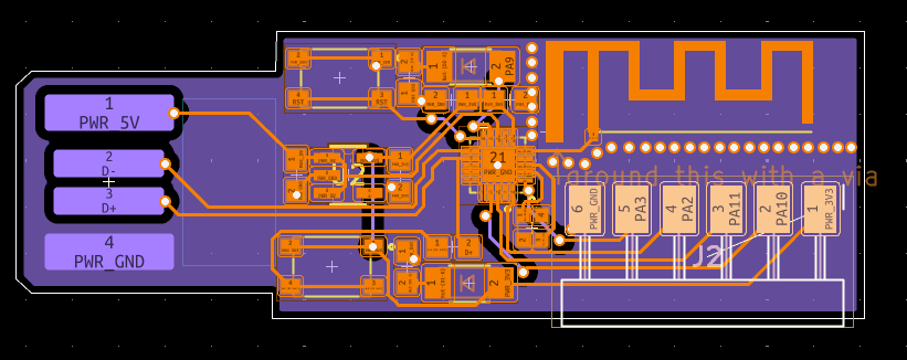 I really cooked here. The first placements were getting the pins and antenna facing away from eachother, and then I saw it fit the size of the USB-A so well, and fit the ch572d in the middle. This is probably my first board that looks actually halfway decent aesthetically. I sadly didn't use curved traces on this one, since I was still experimenting with my style at that point
Okay so thats the dongle, now the code for it
USB Dongle Code
the CH572D, as much as I love designing boards for it, is kinda ass program. I'm talking both writing code and getting it on it. They intend for you to use a WCH-LinkE (USB-Uart board) like a neathanderal, but they also have a tool called WCH-ISP(in system programmer) that lets you program it over USB. With that, it just needs the boot button down during startup, and then can be programmed with a HEX file. It's still a very involved workflow compared to like arduino, as it is:
- Make file in ch32fun
- Put that file into WCH-ISP
- Enable bootloader mode
- Upload Programming wise, im not gonna sugarcoat it, AI is absolutely goated for this. I swear I can program normally, and did have to do parts as ch32fun is simply a pretty niche project, but for the most part, I just had it generate the code for me. Also before I get attacked I spent enough time on that that I can explain all of it, choices the AI made, and the purpose of specific functions, I know a little bit of ball.
Networking Week
In my (revised) networking week, I made the basic functions and such that I'm using here. It works by sending packets like anything else, but these are custom. The main thing about them is that, instead of being sent on the standard Bluetooth access address (0x8e89bede), it uses my own custom formulated hyper advanced algorithmically generated one (0x12345678). This makes it really easy for me (in my debugging) and the chip to know "oh its from the dongle" instead of the wireless toothbrush. Asides from that, I also had it use a 4 byte magic packet (exactly as done in networking week) for even more authentication. The packets were really small though, as it was just those 4 bytes + 3 command bytes (explained later)
Networking debugging
I'm very proud of this part: I used a network analyzer (the kinda thing with a buncha antennas) to see the packets being sent. It actually helped a very very large amount as, again, ch32fun doesn't have the best documentation, and turns out I needed another step to actually send those packets off.
3D Design
Concept and Requirements
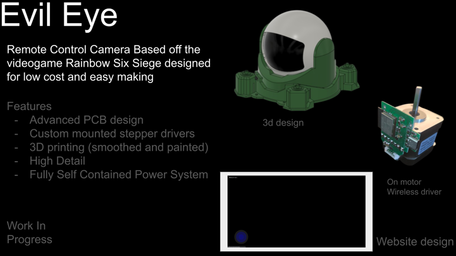
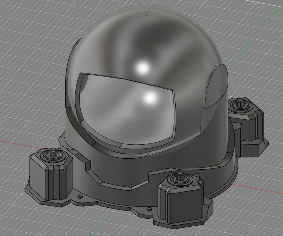
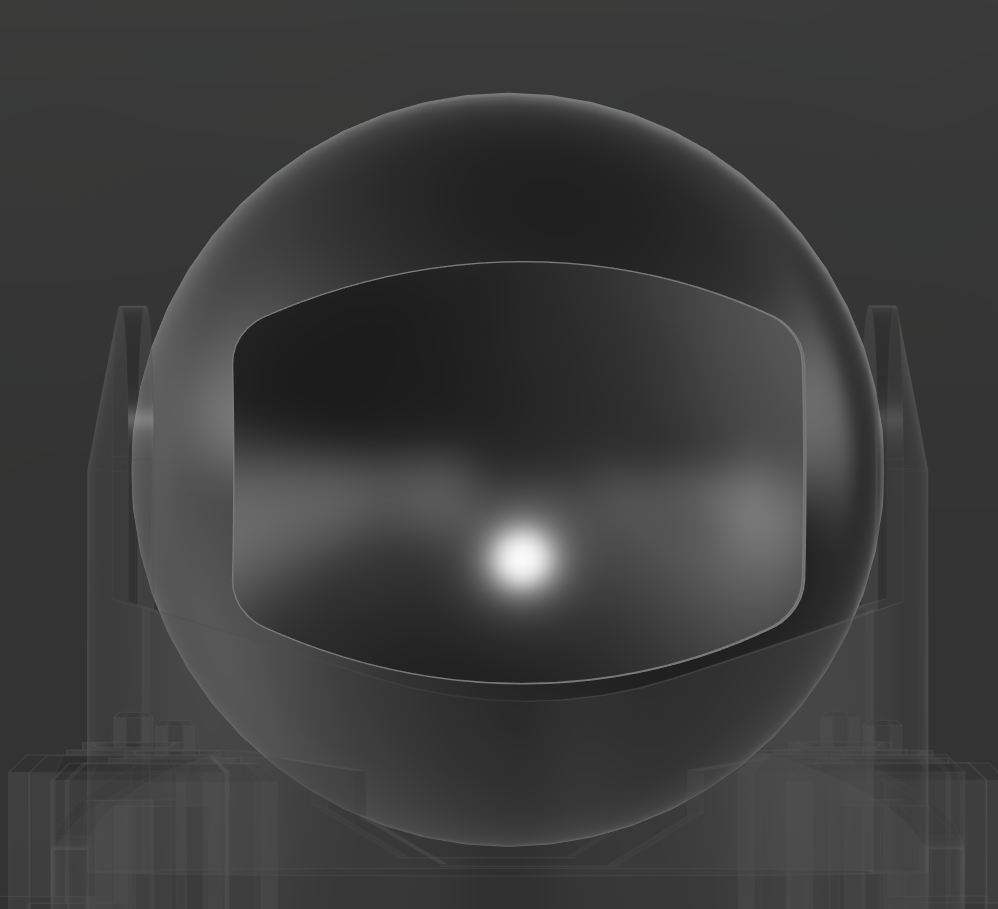
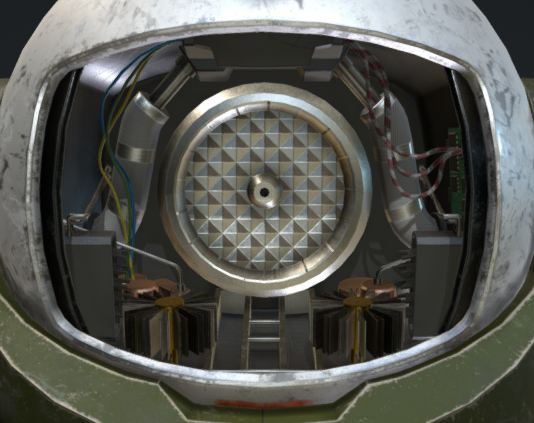
My final project will be a rotatable pan-tilt turret. I will attempt to make it as similar to what it is based on, a gadget from a game called "Rainbow Six Siege". in the game, the "operators" can pull out their phone, and then go on camera to look around. While on their phone, they can move this camera to look in any direction horizontally and around 120 degrees vertically. Additionally, this camera specifically can open the black panel on the front, in order to give the camera an undistorted view. If you go to the 3d model above, and look near the bottom of its box, and change the static pose to moving pose, you can see exactly how it moves in game, and how I want it to move. I also want to keep this working after fab, and put it in my room somewhere, so it has to work well enough to make it out of fab academy alive.
I used this as a reference, its liscense does allow me to modify it with attribute, so my design was based on the one above, which can be found here
Sketch
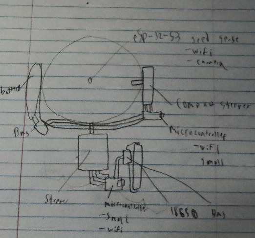 This sketch outlines the major electronic components of the camera. In order for it to be able to rotate infinitely along its base, it needs to have no wires connecting the base and the head, or a slip ring. When I was researching it, while a slipring seemed interesting, I have more experience with batteries and decided to go the disconnected route. It would probably be more reliable or at least easy to replace an old battery than a broken slip ring. I also have some experience with stepper motors when experimenting with making a gantry for them, so I decided to go with a thin stepper for the one connecting the head to the rotatable base, and a larger one connecting the rotatable base to the unmoving base.
First pass
As part of cad week. I designed the 3d portion of my final project. To give a basic overview, I used one sketch per part, with 3 separate parts that I called the unmoving base, the moving base, and the head. both base pieces were not that complicated, and I decided to drop the two levers on the side of the camera so that it would be easier to 3d print it, which is how im planning on making it. in planning on 3d printing it, I had to make sure that a quadrant of it could fit on a bambu a1 build plate, which are the 3d printers my lab has. Besides that, however, I did not design it for being 3d printed in parts, and therefore will have to go back edit it later. This isn't the end of the world, as Fusion 360's parametric modeling feature makes it very easy to essentially time travel to an earlier version of the design, and any changes made in that version will cascade to the current version. Again, for more information, please check my documentation as part of cad week
Refining 3d Design
after getting the code working, for 3d printing and scanning week, I went back to work on the design. for my design in 3d printing and scanning week, I wanted to use a scaled down version of my final and make it print in place, but also used that as an excuse to fix some bad designs, like the head, which I completely redesigned to make it more like the reference.
Continued 3d design
Heres where I finished the 3d design. This entailed really minor changes to the looks of the design, but mainly adding everything that would eventually make it move
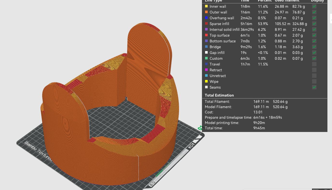 Heres why I wanted to optimize. The current model was 500 grams for just the midsection, but I am confident I can get it down to under a kilogram of filament for at least the 2 parts of the base.
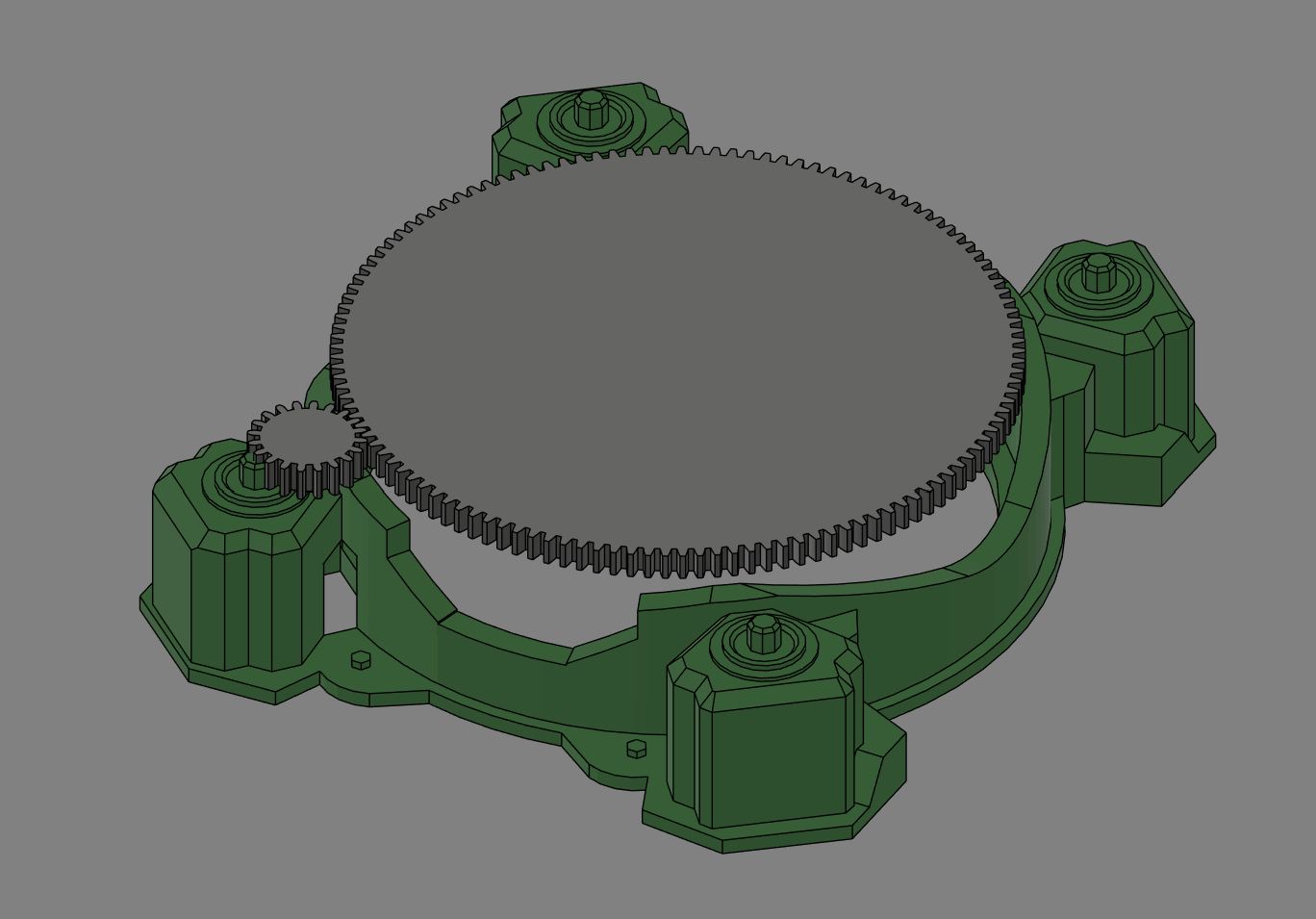
I also started on the motion in my design. This image is a rough sketch of what the gearing for the base will be like
Quick Sticker
To show that I could do subtractive manufactoring, I added a quick sticker bragging about the machine being fully 3d printed. My lab has 2 different types of cameo vinyl cutters, and I choose to use our best, the cameo 4.
Vinyl Design
The vinyl design was pretty simple, I just used sillhoute studio and the text tool to make a simple sticker that said "Fully 3D printed" and then cut it out.
Running the Cut
Vinyl cutters are one of the easiest subtractive machines to use. with the design, I just clicked send to printer, and then stuck some gray vinyl to the top left corner of the cut mat and loaded it into the machine. Our machines do have issues with too shallow cut depth, so I did have to cut the sticker twice. The main issue came after weeding it with tweezers, and the dot over the i was the main issue, but I got it all weeded fine.
Transfer Tape Troubles
The main issue from the vinyl cutter came from our transfer tape. We ran out of the normal tape we use, and I ended up transfering it to the machine with painters tape, which was a much more annoying process. Also, it doesn't seem that PLA adheres to the vinyl well, which was another issue with transfering.
Bill of Materials (BOM)
The following tables outline the Bill of Materials for both the Driver Board and the USB Dongle.
Note: The estimated prices provided are approximate for a hobbyist purchasing components in small order quantities (e.g., 1-10 units) from distributors like DigiKey, Mouser, or LCSC. Passive components (resistors, capacitors) are often bought in strips of 10-100. Additionally, the CH572D is seemingly only found on LCSC or AliExpress. I have purchased from both and both are reputable (if buying from WCH directly).
Driver Board BOM
| Reference(s) | Component | Footprint | Qty | Estimated Price (Each) |
|---|---|---|---|---|
| U1 | CH572D Microcontroller | CH572D | 1 | ~$0.20 |
| U2 | TCR2EF33_LMCT (3.3V 200mA Regulator) | voltage regulator (SOT23-5) | 1 | ~$0.30 |
| U3 | DRV8835DSSR (Stepper Motor Driver) | drv8835 (WSON-12) | 1 | ~$2.00 |
| E1 | AMCA31-2R450G-S1F-T3 (2.4GHz Antenna) | pcb antenna | 1 | ~$0.80 |
| Y1 | 32MHz Crystal | 32mhz crystal | 1 | ~$0.30 |
| J1 | 12402012E212A (USB-C Receptacle) | usbc | 1 | ~$0.60 |
| J2 | Motor Out (1x4 Pin Header) | PinHeader_01x04_P2.54mm_Vertical_THT | 1 | ~$0.10 |
| J3 | Power / Misc (1x2 Pin Header) | PinHeader_01x02_P2.54mm_Vertical_THT | 1 | ~$0.10 |
| S1 | TL3365AF180QG (Tactile Button) | button | 1 | ~$0.30 |
| C3 | 100uF Capacitor | C_1206 | 1 | ~$0.20 |
| C6 | 2.2uF Capacitor | 0603 | 1 | ~$0.05 |
| C2 | 1uF Capacitor | 0603 | 1 | ~$0.05 |
| C1, C4, C5, C7 | 0.1uF Capacitor | 0603 | 4 | ~$0.02 |
| R1, R2 | 5.1k Resistor | 0603 | 2 | ~$0.02 |
| R3 | 1.5k Resistor | 0603 | 1 | ~$0.02 |
USB Dongle BOM
| Reference(s) | Component | Footprint | Qty | Estimated Price (Each) |
|---|---|---|---|---|
| U1 | CH572D Microcontroller | CH572D | 1 | ~$0.20 |
| U2 | TCR2EF33_LMCT (3.3V 200mA Regulator) | voltage regulator (SOT23-5) | 1 | ~$0.30 |
| E2 | 2.4GHz Antenna | antenna | 1 | ~$0.40 |
| Y1 | XRCGB32M000F2P01R0 (32MHz Crystal) | 32mhz crystal | 1 | ~$0.30 |
| J1 | USB_A_PCB_Edge_receptacle | USB_A_PCB_Edge_receptacle | 1 | ~$0.00 (PCB Edge) |
| J2 | 1x6 Pin Header SMD | PinHeader_01x06_P2.54mm_Horizontal_SMD | 1 | ~$0.20 |
| S1, S2 | TL3365AF180QG (Tactile Button) | button | 2 | ~$0.30 |
| D1, D2 | PWRLED (Indicator LED) | LED_1206 | 2 | ~$0.10 |
| C6 | 2.2uF Capacitor | 0603 | 1 | ~$0.05 |
| C1, C2 | 1uF Capacitor | 0603 | 2 | ~$0.05 |
| C7 | 0.1uF Capacitor | 0603 | 1 | ~$0.02 |
| R3 | 1.5k Resistor | 0603 | 1 | ~$0.02 |
| R4, R5 | 330 ohm Resistor | 0603 | 2 | ~$0.02 |
3D Printing Materials BOM (For my specific use, custom will be higher/lower)
| Component | Description | Qty | Estimated Price |
|---|---|---|---|
| Filament | Bambu Lab PETG | 1 kg | ~$25.00 |
Final Project Q&A
What does it do?
My final project is a turret with an infinitely rotatable base that can look in full 360 degrees. It has an internal battery, and is fully 3D printed.
Who’s done what beforehand?
A couple similar projects have been made before, but they generally use servos, such as this one. The difference is while those use servos, mine use steppers because:
- I need high torque, and a geared stepper can provide that.
- I need to be able to rotate a lot, as most servos tap out at 180 or 360 degrees, although there are infinite rotation variants.
What did you design?
With the help of this model as a reference, I designed all the physical parts of my project myself in Fusion 360. For the electronics, I fully designed the consolidated driver board featuring the CH572D microcontroller and the DRV8835 driver, as well as the custom USB-A dongle board (available on my GitHub).
What sources did you use?
As I described above, the main source was what I used in my 3D design, which was this model. I also used various datasheets, the big ones being the CH572D datasheet, my motor driver's datasheet, and cnlohr's open-source ch32fun repository examples.
What materials and components were used?
Higher detail of this can be found in my bill of materials. In general though, I am using 3D printed components, printed in PETG if at home and PLA if at the lab. For the project, the 4 base pieces were made of PETG, the middle base was PLA, and the head was made of multiple PETG pieces. For the electronics, it used professionally ordered double-layer PCBs. The important components are the 20-cent CH572D microcontrollers (used on both the driver board and the custom USB dongle), the DRV8835 low-voltage stepper motor drivers, and a pre-made charge-discharge battery module from Amazon. For the window, I ended up using clear acrylic instead of casting a mold.
Where did they come from?
I prioritized getting the parts from DigiKey, and the CH572D chips from LCSC/AliExpress. The battery charger module was from Amazon, and the filament was purchased from Bambu Lab directly.
How much did they cost?
The total cost for all components was around $50, with the main brunt being 1.25kg of filament, coming in at around $25 total. The second most expensive were the 2 stepper motors, which were $7 each. The rest of the components cost me more since I bought in bulk, but if buying the exact requirements for this will come out to around $15 total, including ordering the PCBs (pre-tariffs).
What parts and systems were made?
The main focus was on PCBs, including my custom driver board and the USB-A dongle board, which are pretty good (for someone with no formal training), but also the making of the designs, especially around how this is almost entirely 3D printed. In the code, I made a custom 2.4GHz wireless packet protocol (on channel 37 with magic packets) to communicate between the USB dongle and the turret receiver, and the web joystick interface to control it.
What processes were used?
The processes used include:
- 3D parametric modeling (Fusion 360)
- 3D printing (PETG/PLA)
- Sanding, priming, and painting
- Electronic schematic layout and PCB design
- Hot-air SMD soldering and assembly
- Custom wireless firmware programming
What questions were answered?
What worked? What didn’t?
How was it evaluated?
What are the implications?
Design Files
Due to the size of the 3D files and PCB designs, the design archive has been split into 4 parts. Download all 4 parts below:
- Download Design Files - Part 1 (10.0 MB)
- Download Design Files - Part 2 (10.0 MB)
- Download Design Files - Part 3 (10.0 MB)
- Download Design Files - Part 4 (5.9 MB)
How to Unzip the Split Archive
To reconstruct and extract the files, follow these instructions based on your operating system:
Windows (Using GUI)
- Download all 4 files above and ensure they are saved in the same folder.
- Download and install 7-Zip (highly recommended, free) or WinRAR.
- Right-click the first file
designfiles.zip.001, select 7-Zip (or WinRAR), and click Extract Here or Extract to "designfiles/". - The software will automatically locate the other parts and combine them into a single folder containing all of the design files.
macOS & Linux (Using Terminal)
- Download all 4 files into the same directory.
- Open your Terminal and navigate to that directory.
- Run the following command to merge the parts back into a single zip archive:
bash
   cat designfiles.zip.001 designfiles.zip.002 designfiles.zip.003 designfiles.zip.004 > designfiles.zip
- Extract the merged archive:
bash
   unzip designfiles.zip
Windows PowerShell (Alternative Command Line)
- Download all 4 files into the same folder.
- Open PowerShell in that folder and run:
powershell
   Get-Content designfiles.zip.001, designfiles.zip.002, designfiles.zip.003, designfiles.zip.004 -Encoding Byte -ReadCount 0 | Set-Content designfiles.zip -Encoding Byte
- Extract the generated
designfiles.zipusing the built-in Windows Extract tool.
License
I've learned so much from open source and the community during this project, so keeping it closed off would just be messed up. Honestly, my product doesn't really have extreme commercial value right now, and it's completely against the spirit of making something so community-driven to then turn around and lock it down when people want to make it or modify it themselves.
Because of that, I decided to go with the MIT License. It's basically the most "do whatever you want" open-source license out there. I chose MIT because it allows anybody to create, edit, distribute, and even commercialize my final project without any headaches. All it requires is that you include the original copyright and license notice. Just giving credit is enough for me, since the whole point is just to put cool stuff out into the world and see what people do with it. Also so that if something goes wrong with other projects based off/inspired off this, I'm not as too blame (✿◕‿◕✿)
Acknowledgements
This project was built on the shoulders of the open-source community, and I want to extend a massive thank you to the creators whose work made this possible:
- ch32fun: An incredible open-source development environment for WCH microcontrollers created by Charles Lohr (cnlohr). This was absolutely critical for programming the CH572D without being locked into proprietary IDEs.
- Gear Bearing by emmett: This print-in-place design from Thingiverse served as my direct inspiration for conceptualizing and designing the 3D-printed gear bearing in the turret base.
- GF Gear Generator: A powerful Fusion 360 add-in that saved me an enormous amount of time accurately modeling the internal drive gears.
- Rainbow Six Siege 'Evil Eye' Model: The original reference model uploaded to Sketchfab that I based my external shell design upon.
- NippleJS: The fantastic virtual joystick library utilized in my web-based controller interface.
- Nicholas Niles: Huge thanks to fab academy graduate and PCB design engineer Nicholas Niles for reviewing my board layouts and providing just the most wounderous great advice advice on trace routing and curved corners.