Output Devices
This weeks task was to measure something: add a sensor to a microcontroller board that you have designed and read it.
Actually using the servo was kind of hard. This is mainly due to the servo motor library that everyone uses, the one built into the arduino IDE not working with esp series chips. Also, the servo I used was made for 5v, but my board is 3.3v. I found that using the raw usb output (roughly 5v) worked. It isn't advisable to connect a 3.3v dataline into a device powered by 5v, but it usually works. NEVER connect a 5v data line back into a 3.3v microcontroller, as that is the thing that will always permanently break the pin its connected too, and probably go far enough to brick the entire chip.
going back to the programming bit, after finding that the library didn't work, I used AI to create code to drive a stepper without a library. The AI created code
Servo
This was done last, but in order to make this week somewhat readable, in putting it up here
Programming
Im using the custom esp32-c3 board i've made here again. I started this week with hopes of using the board I designed below, but through hole milled components hate me and I hate them back.
Using a esp module in general was a pain, as the servo library built into the Arduino IDE does not support the esp series of boards. Looking at it right now, its actually crazy that such an established library does not support the esp series, rp2040 and its continuations, and any stm microcontrollers. I guess Arduino has to make money somehow, and making using a servo easier on their boards is a good way to sell them. I found that the other libraries didn't work, but that was probably due to a power supply issue with my servo that ill touch in the wiring section below. Because of that issue, I jumped between code multiple times, eventually understanding the servo and making a no library servo driver. This was a waste of time, and I would suggest the esp32servo library when using a esp32 with a servo. that library is really easy to use, as it just needs you to attach a pin to a servo, then set an angle. that is 2 lines of code to control a servo, very simple, very human.
My final code with comments ended up being this:
int servoPin = 0; // PWM pin required, dont worry about that if your using any board made in the past 15 years

void setup() {
  pinMode(servoPin, OUTPUT);
}

void loop() {
  // Sweep from 0 to 180 degreesw
  for (int i = 0; i <= 180; i++) {
    writeServo(i);
    delay(15);
  }

  // Sweep back from 180 to 0 degrees
  for (int i = 180; i >= 0; i--) {
    writeServo(i);
    delay(15);
  }
}

void writeServo(int angle) {
  int pulseWidth = map(angle, 0, 180, 500, 2500);
  // servo works by taking a pulse 500-2500 small seconds(I dont have the micro symbol), and then the duration of that pulse is directly related to the angle it will end up at
  // ! the servo I used was the sg90s , which uses those specific timings, other servos will use different
  // Send a 50 Hz signal (one pulse every 20ms), its just what most servos use, dont change this probably
  digitalWrite(servoPin, HIGH);
  delayMicroseconds(pulseWidth);
  digitalWrite(servoPin, LOW);
  delay(20 - (pulseWidth / 1000)); // total time between waves is 20ms minus the amount of time it needs to communicate the angle, don't worry about this, it just works
}
Wiring
Wiring the servo was really easy, with one caveat. I started with simple 3.3v to the servos red wire, gnd to the servos brown wire, and pin 0 to the servos yellow wire. After this didn't work, which I thought was due to code, I eventually switched it to my microcontrollers 5v pin, which finally gave it enough power to not just sit there and vibrate like a dying animal. After that, it did have times where it would move much faster than others, and I think thats due to the usb-c port of the microcontroller not able to request additional power, and therefore being limited at 600mah split between the servo and microcontroller. My voltage regulator is also limited at 600mah, so even using an external 5v power source would not allow it to get enough power. In the final project, this will hopefully not be a issue, as im using a xiao esp32-s3 sense for the head, but it will be powering a camera (from on chip), stepper (not directly) and servo (not directly). Not directly means that im planning on driving it directly from battery, but depending on the ability of the Xiao I definitely want to drive the stepper from it so that the logic levels are aligned
Design
This is the big stuff that I talked a bit about last week, but heres the full detail. This is an almost exact copy of what im putting in my final project page, but this probably won't be updated past me finishing this week. If you want v2 of the design, check out my final project page
Requirements
Battery Support
Needs to be able to operate off of a single 18650 battery cell, this cell will be 3200mah, and was purchased from a U.S. retailer here.
Wifi Support
This is pretty simple for me, and is part of the the microcontroller im using. As with the other boards i've made, I plan on using a esp32 series chip, almost certainly the esp32-c3-wroom-02. Im very comfortable with using this chip, so it was the obvious choice
Stepper Driving Capabilities
It needs to be able to drive a stepper, after doing research the primary plan for this was a custom driver board, based off the (DRV8835). I choose it primarily because I saw this board from Pololu, which used it, and just looking at the board it needed like 4 components to work. Doing research, it was perfect for my project as it
USB-C
while usb micro is easier to work with, thanks to its pinout being 5 pins, vs the USBC's 16, and the USBC requiring at least 2 resistors to work, and specific capacitors on the data lines if It was a professional project. I don't care however, as the USBC will hopefully only be needed to be used once before switching to to an OTA update configuration so I am going with the bare minimum for this
Schematic
After selecting components based on my needs, I started with the schematic. As I intended this to be a "frankenstein" board, I started by designing a footprint for the pads I would use pads to intersect here. Here is where I messed up and fixed it later, as I originally intended to connect the pads so that they were really long. I realized that this would be very hard, as solder likes to pool in the middle. To make it easier, I made the pads connect so that they would form a square, which would
Component redesigns
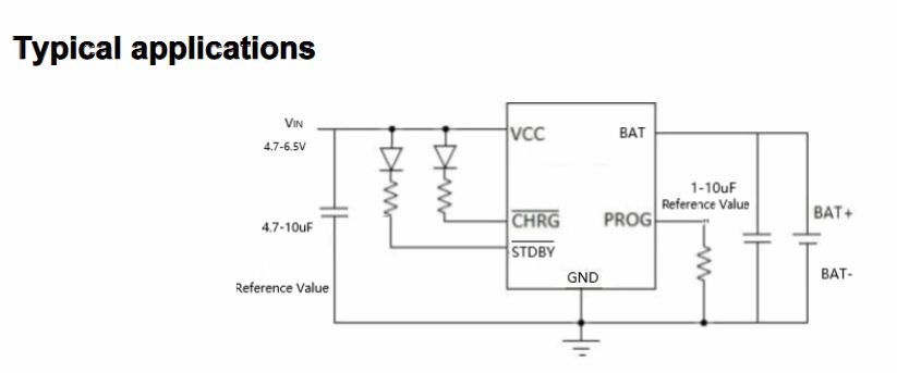
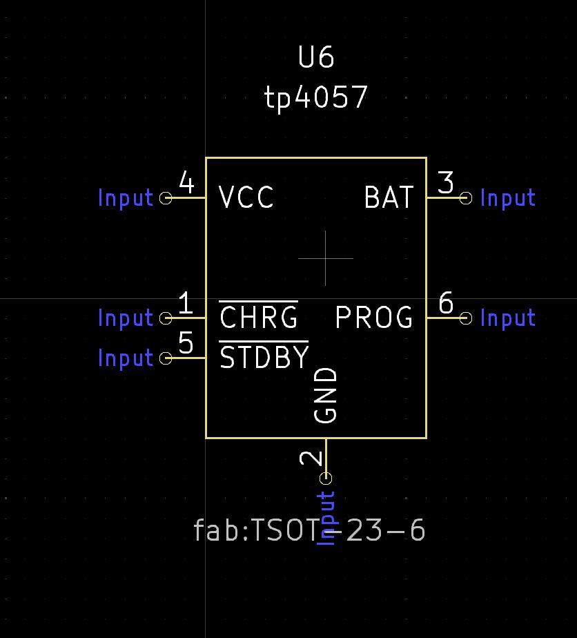
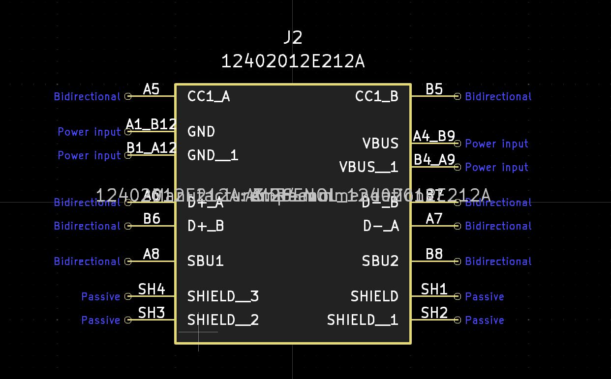
In order to more easily use some of the components, I went and redesigned the schematics of them. This includes the tp4057 IC, which I redesigned to look identical to the example I found, and the USB-C module I use, which I moved the pins around so that it was much cleaner to work with
Layout Guide
I started the laying out the components with my microcontroller. For this, I took the exact design I made in week 8.
I then took the USB-C layout from my custom microcontroller. I then had to figure out battery and the driver.
For the battery, I found this example image on the datasheet of the tp4057, as well as this github repo showing an example circuit using the tp4057
For the stepper driver, Texas Instruments (the IC designer) is known for having really good datasheet with application diagrams, and they didn't disappointhere. Specifically, Section 10, "Layout" featured the optimal layout for the chip.
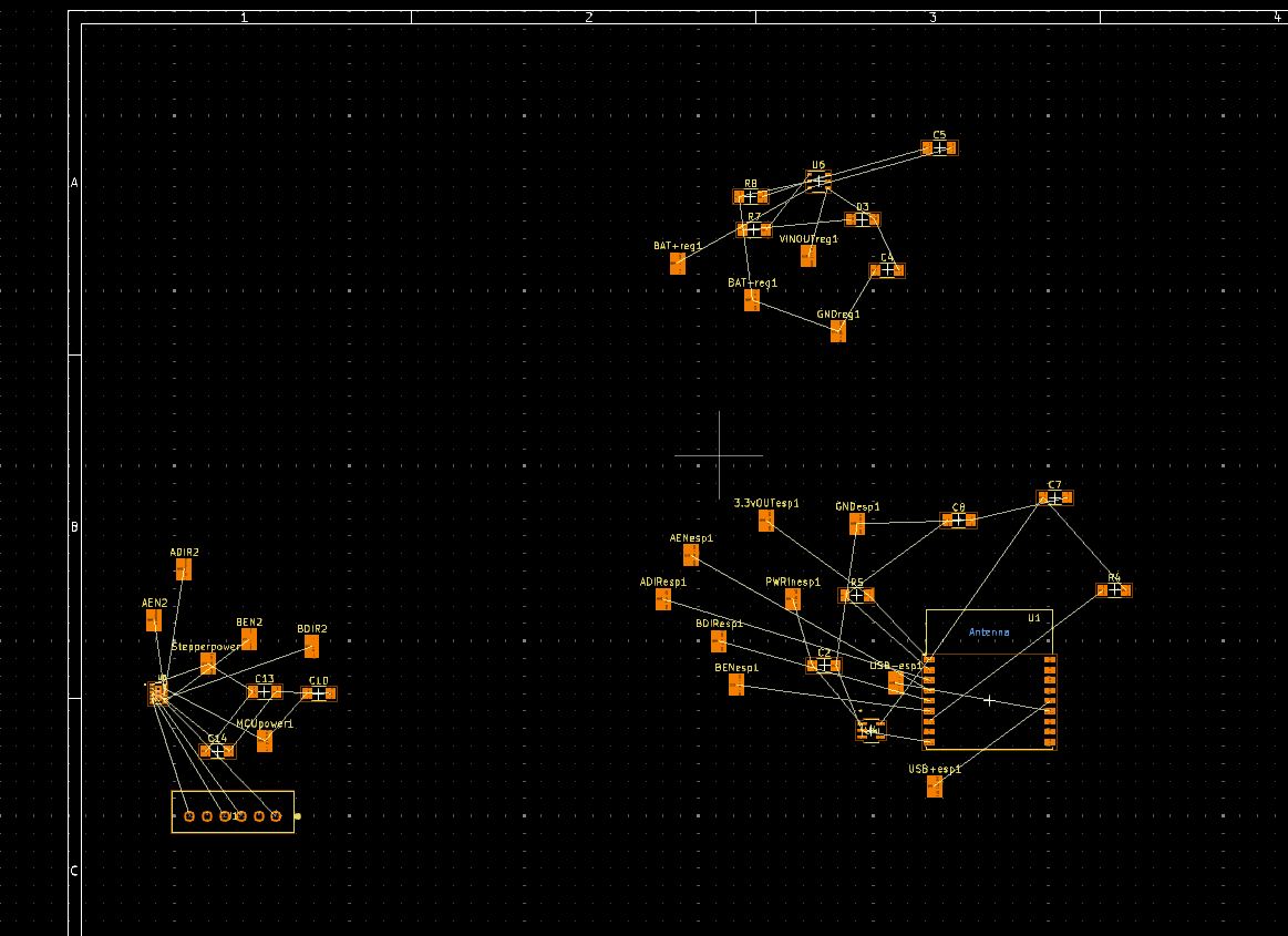
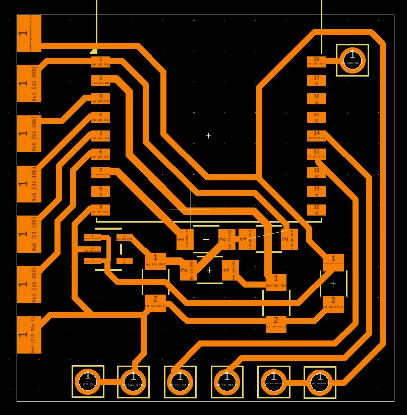
Actual Layout
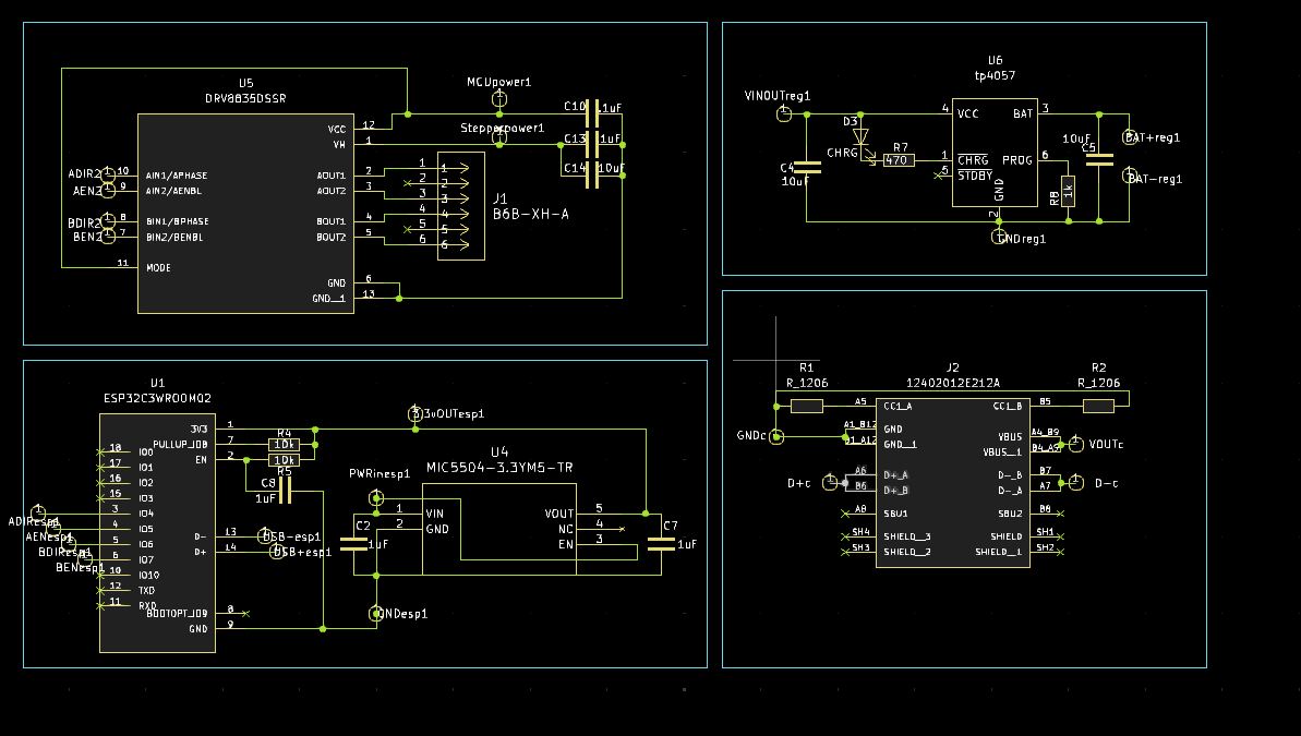
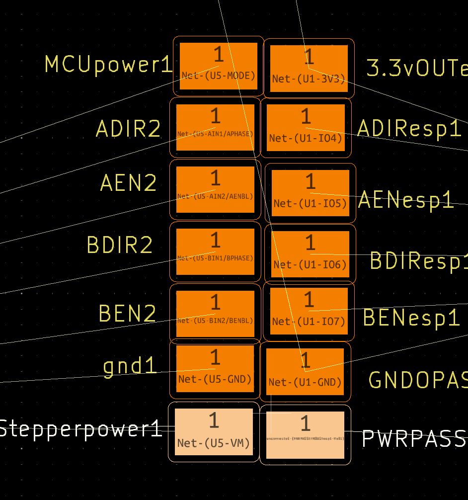
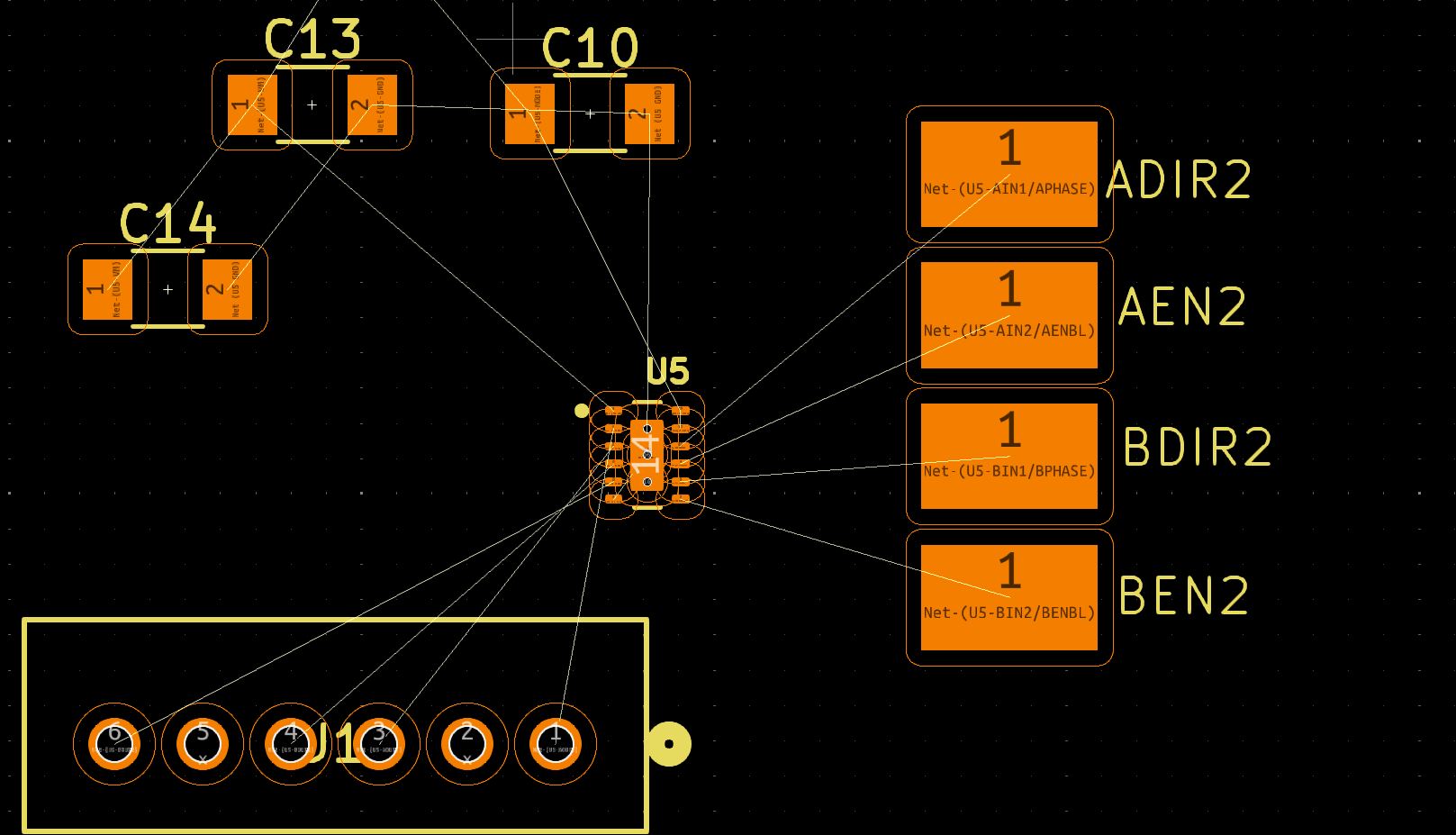
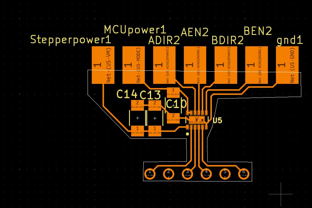
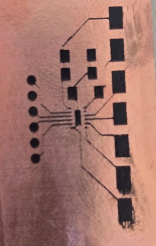
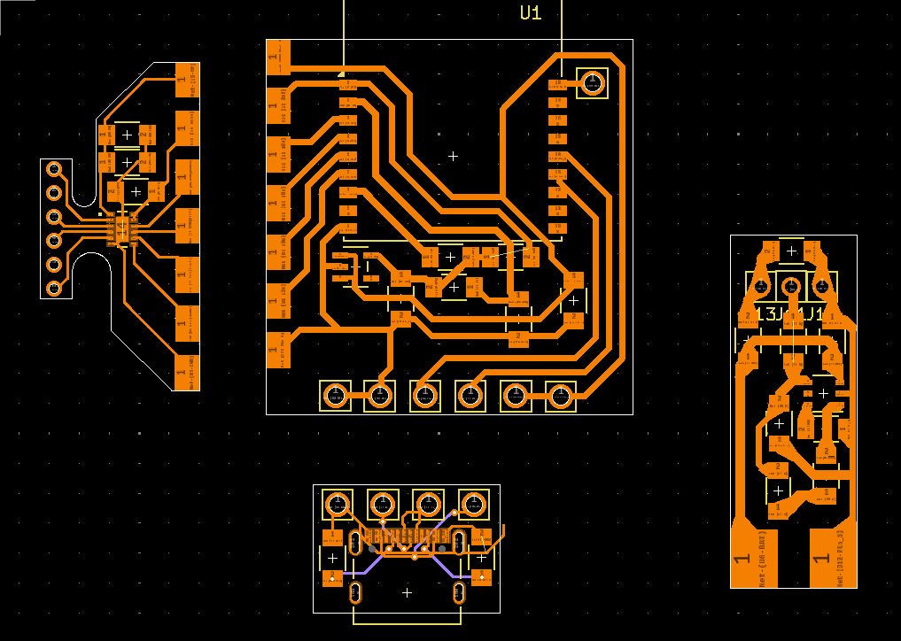
The layout for this was 4 different separate blocks, which would eventually turn into 4 separate PCBs. Kicad, or at least the way I used it, struggled a lot here. This is because I cannot make 4 schematics on one page, then specify that I want them to be for disconnected boards when importing into the PCB editor. this lead to me having to manually sort the components into the board, which was not intuitive. The actual design was, but I had to keep in mind where the boards would connect, and include pads on each side of that. For example, I had to break out the 4 pins for controlling the driver (see the bottom left of image below) from the microcontroller, and also include those in the stepper portion (see the top left of the image)
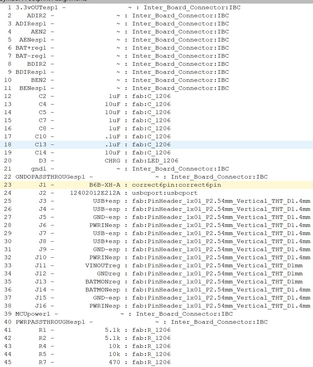
Footprint Assignment
For the footprint assignment, it was just matching the references with the proper component. I also had to make sure to match any special named thing with its specific component, being either a jumper or a pad(what I call IBC, or inter board connector)
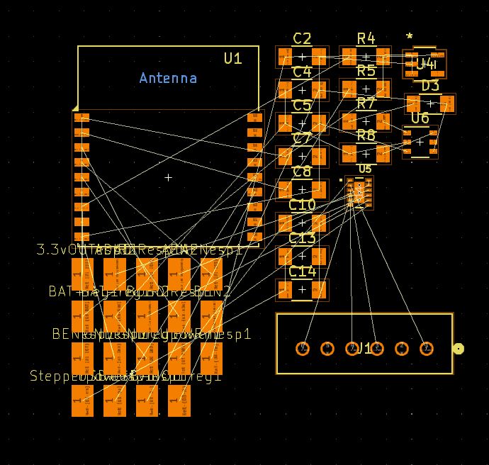
PCB Design
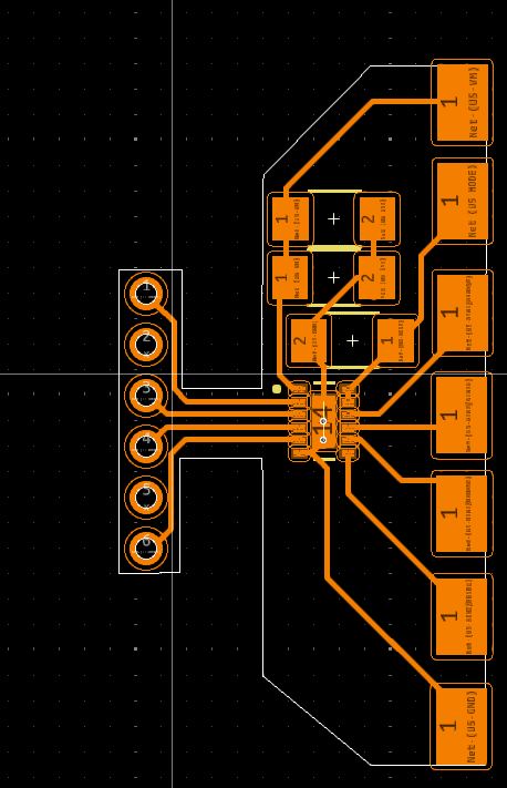
after finishing the schematic, I started on the design. Because of all of the designs (except for the USB-C) being intended for milling/at home fabrication, I had to be smart with how I routed. I ended up having to use 2 zero ohm jumpers in the board, in order to make the design possible. This isn't the best possible outcome, but its what I got and if I redesigned it to use traditional jumpers (which I should), then it could probably be made with none of them.
Here is where the issue I talked about in the actual layout section comes back. When I went to import the footprints, it imported them all mixed together. This meant I had to resort them all back into groups
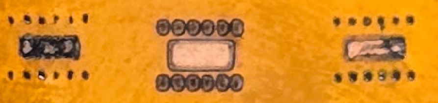
Pads
For connecting my boards, later on reduced to only being between the stepper driver and microcontroller, I used pads that would be directly soldered together. This is based on the principal that I see with XIAO boards being soldered directly onto PCBs, and I was hoping to recreate the same thing. The first design of the pad had them connecting to form a rectangle, but upon rethinking it, specifically in regards to how solder pools in the middle of pads, I redid them to have it form a square when they are connected. The original version of the pad can be seen in some images below, but were all replaced by through hole jumpers or the better pad
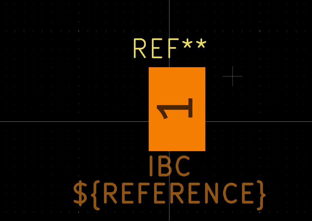
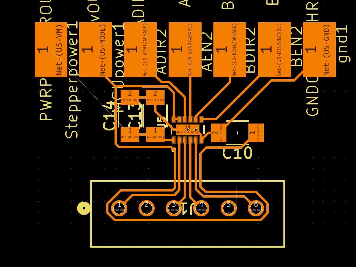
the exact order of the pads was important, as it would make designing the board later on. The main thing was that the esp32-c3-wroom-02 module has 3.3v come in on the top left, gnd come in on the bottom left, and pins in th middle of that. This played a big role in my design in the order of the pads, where 3.3v comes at the top, followed by the 4 pins for controlling the stepper, then the ground. Later on in the design, I also added a power passthrough from the battery board, which went on top of the 3.3v, as it was most convenient placement for the driver board

 These images are from early on, but summarize how they should connect
USB-C module
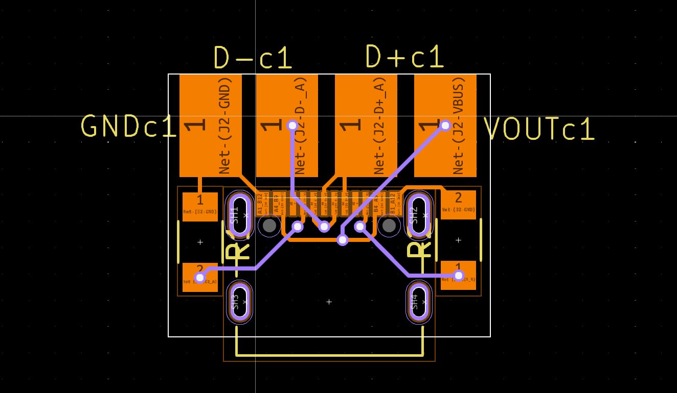
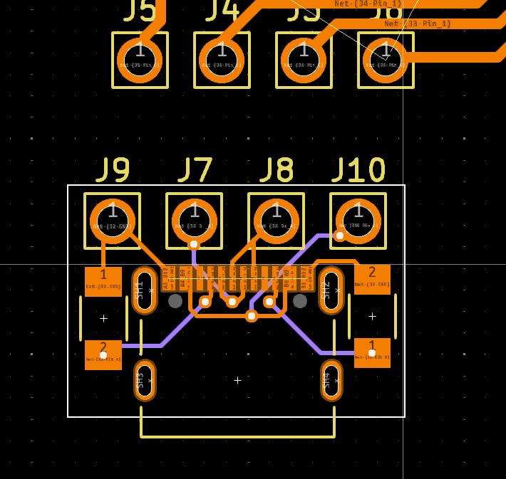
I started by designing the USB-C module. I originally intended for this to be soldered with the pads onto the microcontroller, with it being on the opposite side as the stepper driver and stepper connections, but after looking at the size that it would take up (it would reach the steppers metal shaft), I had to pivot to using jumpers. I changed it before I used the new pads, which showcases the old pads.
V1
 V2
V2
this is the one board that I have to order from a boardhouse, as vias are ~~impossible~~ really hard to make
Safe minimum required for a functional USB-C module
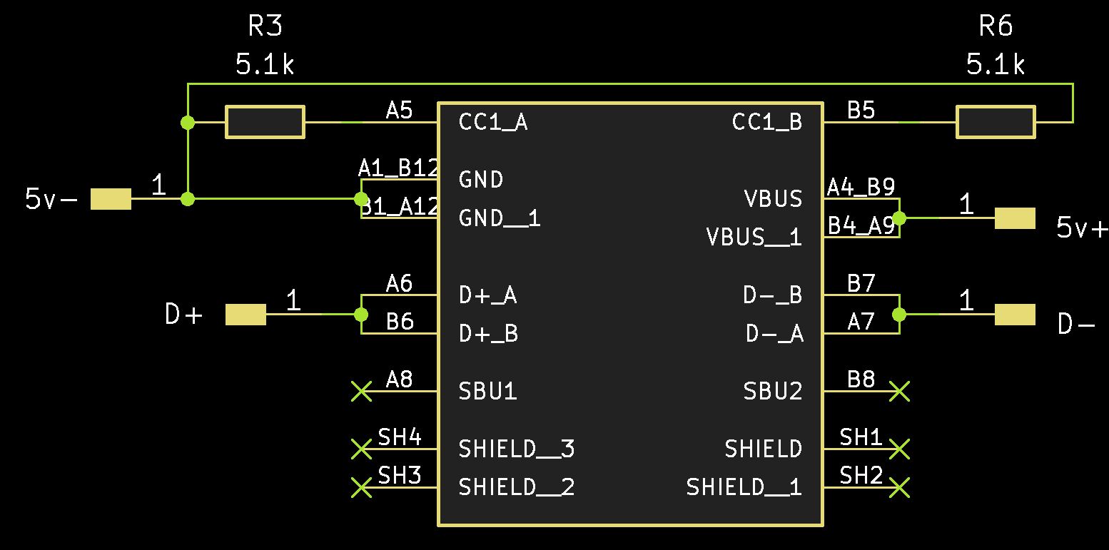
As a general outline for a USB-C module, you need to have a usb c connector itself that isn't just power only. It will be advertised as something along the lines of 24 pins (16+8 dummy). Keep in mind that 6 pins is not enough for data from a USB-C, although it is the first result on digikey. After choosing your connector, you have to pay attention to the CC pins, which negotiate the power you want through resistance, the VBUS pin where power (5v without a special IC), GND where ground comes in, and D+ and D- where data+ and data- come in. Because USB-C works upside down as well as rightside up, there will be 2 of each pin. You want to connect the two pins together, except for the CC pins, where you NEED individual resistors for each pin going to ground. If you want to be super safe, mostly because you don't trust your computer's usb ports, you can add 22pf filtering capacitors between each dataline and ground. From my experience, this is not required, but if you have a really bad cable, use it.
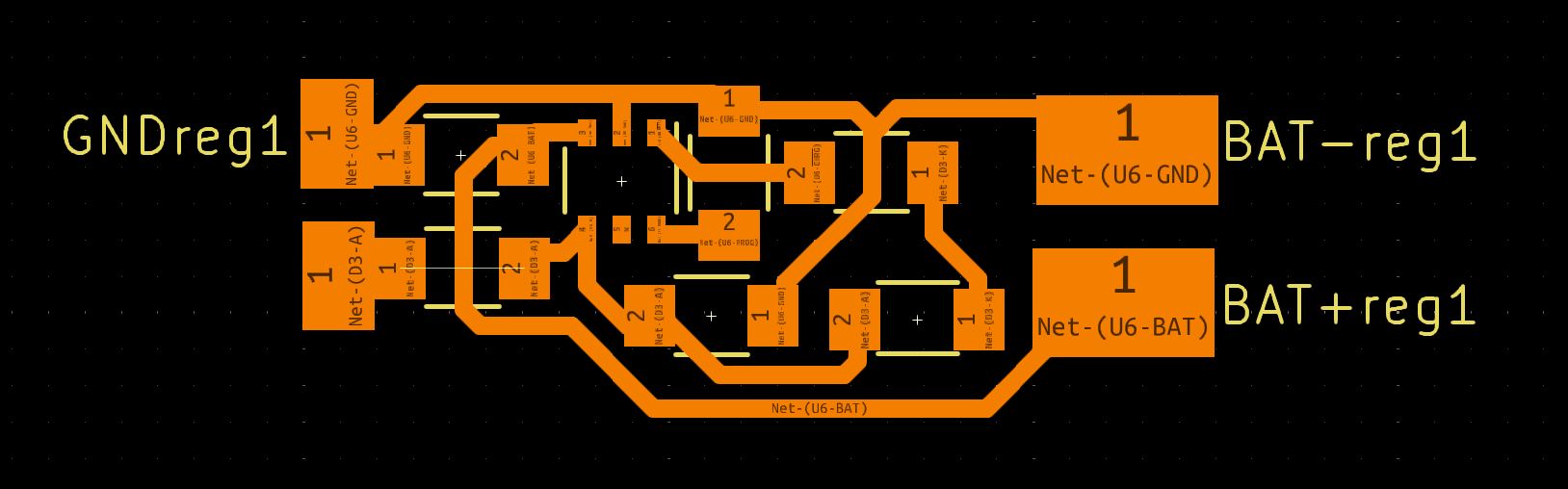
Battery
For the battery, it was very easy to design. The only problem I encountered with it was a wire that I could not get through. This was designed for milling/etching, so I made the traces .5mm. Also, with high power stuff (higher power than this case), a higher trace width, or even better, a thicker copper layer (the default is a 1oz, or .35 micron, doubling that is safe for higher powers).
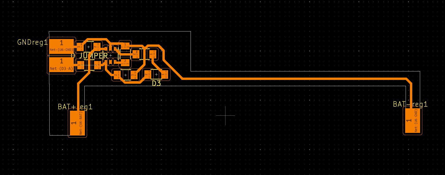
I started out the design intending to slot the battery between the pcb, but after thinking (about the wasted copper), I decided to compact the board more and use wires coming off of the board instead. This is one of the only places I still used pads, and I used larger pads than what I used for connecting the boards
 After my first attempt at milling it, my through holes failed. I tried fixing this via teardrops, which are essentially traces with width that decreases as they go away from the pads
Battery Monitor
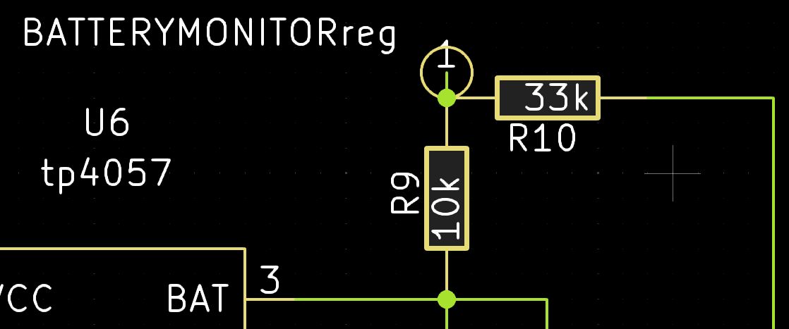
In making this, I realized that the tp4057 did not have an over-discharge protection. I added a quick fix for this, being a voltage divider that would allow the esp32-c3 to monitor the battery, and put itself in deepsleep mode when it detected too low power. This would work fine, as deepsleep mode would take upwards of 5 years to run out of power(going under the unsafe threshold of 2.5v) after reaching 3.2v.
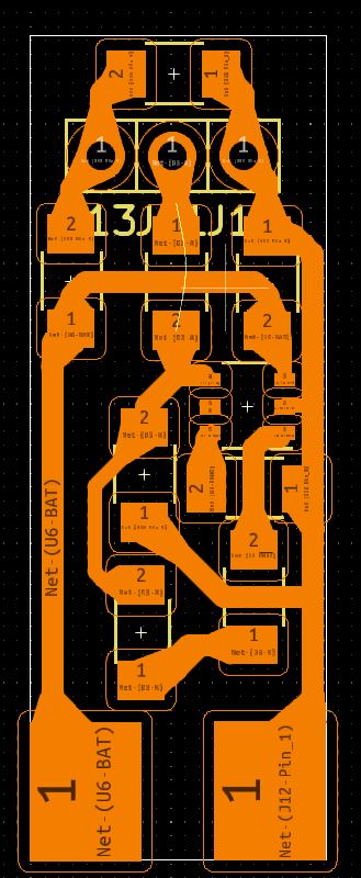
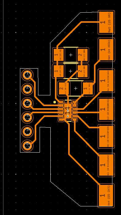
Stepper Driver
The driver is honestly pretty simple. The chip itself isn't a driver built for steppers, unlike the A4988. The reason im not using a a4988 is that the voltages im using are too low. from my testing, the a4988 can run on 3.3v, but frankly, this should not be possible according to the datasheet, and I would rather this project works for longer than a couple days. The driver itself looks really good, as its a dual h bridge, which mean it can drive 2 coils. This is good, as stepper motors have 2 coils inside them, which allows for exact positioning.
 Comparing a trace width of .5mm to the driver, it shows that it will be impossible to mill
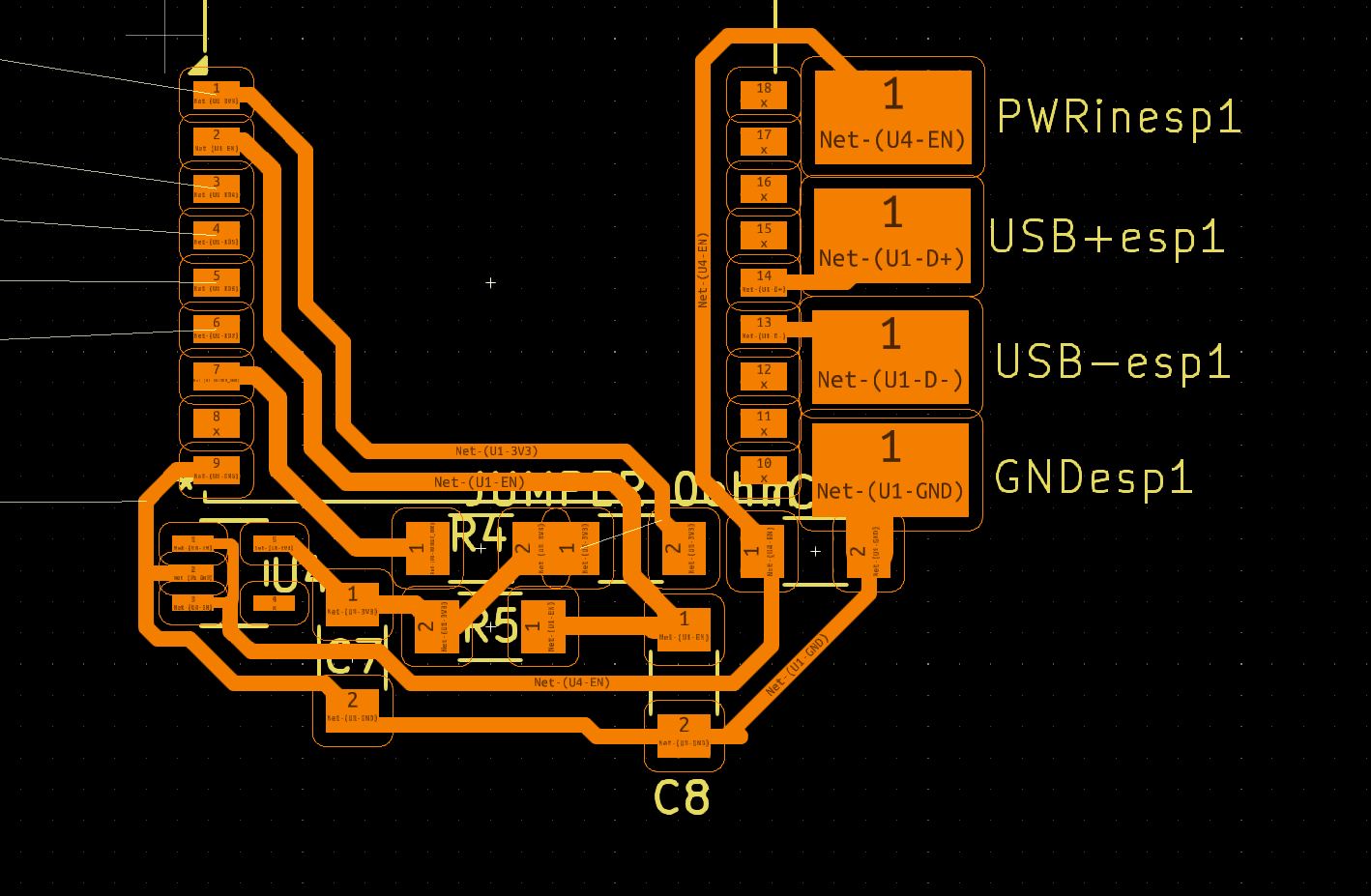
Microcontroller
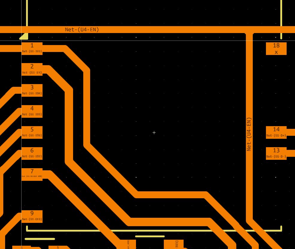
This was the most complicated design. I originally started with my design for week 8, but then built off it. The original thinking was to connect everything with pads, but as I realized size constraints, I switched over to jumpers. The entire board is basically a esp32-c3, filtering capacitors for it, a 3.3v microcontroller, and filtering capacitors for that.
I also (shamefully) had to make use of one 0 ohm jumper in the circuit, in order to ground the voltage regulator
 In building it, I also though about making it through pcb etching, similar to what I did with the battery module. for that, I could manually edit the footprint of the esp32-c3 to remove pads that I didn't use. This allowed for the board to be compacted a bit more, and I just had to remember to not solder it straight to the traces
I ended up reverting that, as when I started to convert to jumpers from pads I placed one of the pads (battery monitor) near where it was actually needed, so that I could revert the footprint and make soldering easier.
Making all the stuff
Very proud of this section
Making the battery board: Etching
New process for me. Im trying etching, which ive never done, but also using the laser cutter as part of it, which is super never done. The laser cutter is used similar to my previous experience with using a cutter in pcb making. Instead of making a stencil with paper, I used kapton tape to make a mask, which then covered most stuff while etching
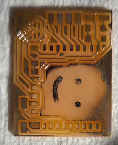
My first ever etch was just pouring some ferric chloride on an old board, while using a sharpie marker to cover up some parts. This allowed for a smily face to be made, and took only 5 minutes using the sponge process
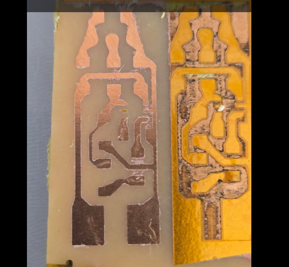
After that, I moved onto testing out using tapes to etch. After trying alot of tape, I found that, generally, the thinner the tape was, the better it preformed. Kapton tape is also really good for this since it is meant for high heat resistance, which means it wouldn't melt as bad vs other tapes. I found that low power, many passess worked well to preserve accuracy, my final settings ended up being 4 passes at 45% power, 1200dpi, engraving not cutting. This took around 10 minutes, and gave the results below
I then engraved. A big problem I ran into here, that caused my first board to fail, was I was scrubbing it to hard, which pulled off one of the trace lines. This is where I went back and decided to add in teardrops to everywhere on the board, which thickened the traces alot and allowed the second to succeed
Making the microcontroller: Milling
The ol' fab special. Honestly not that bad, except for the through holes. My first mill failed, but after help from a fab-mate, tyler, who suggested switching to a 1/32inch bit for the through holes. I almost always do 1/64 for everything else
Making the USB-C: Ordering
My engineering teacher likes to say that you can't have speed, quality, and cheapness at the same time; you can only have 2/3
ordering it is quality and (relative) cheapness
I already covered ordering in week 8, so go there for a workflow. I also ordered everything as a "safety net", as I ordered all 4 boards I designed since the main cost is shipping. This ended up being just over 10$ for 20 boards, 5 of each. These are the highest quality I can get them, because ~~im not touching them~~ this is what they specialize in
Making the Stepper driver: Ordering
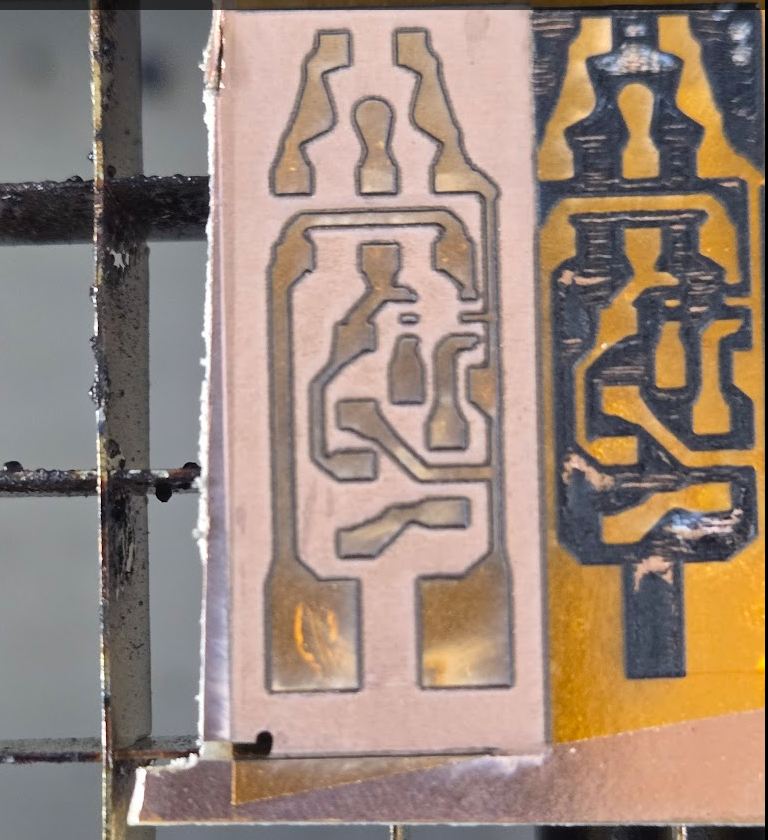
While I had dreams of making the board myself, and got very close to it with etching, By the time I got a board that was close, I already was 2 days off from the board arriving, and therefore just decided to wait. The main problem was the chip, which was way too small to use
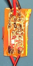
In my experiments trying to etch a board that small, I got very close. I found that for increased accuracy, instead of burning fully through around it, I could half melt eletrical tape to get really small details.
This came with some flaws however, as it resulted in too thin traces, as well as being a "wet" material that I could move with my thumb, as seen by the bottom left having a fingerprint in it.
Using
Heres where it all came crumbling down, im going to list from how well they worked to how unwell they worked
Battery Board
the battery board actually worked fine. Using it, I was able to charge through an external USB-C connector, and then discharge through the VIN/OUT pin I set.
USB-C Board
Early in the process, I ordered an early version of my USB-C board that used pads. It arrived around the same time as I finished milling my esp32-c3 board, so I decided to use them together. The USB-C portion worked fine, as I just soldered jumpers onto the pads, but didn't solder the two boards together as that plan had changed
ESP32-C3 Board
 This one was horrible to work with. In week 8 and 9, I discovered a love for milling machines, here, I discovered a hatred for the milling machines. In week 8, I figured out how to do through holes with the help of a fellow fab-mate, Tyler. This week, I discovered that no matter how good the through holes were, they would still break themselves every chance they got
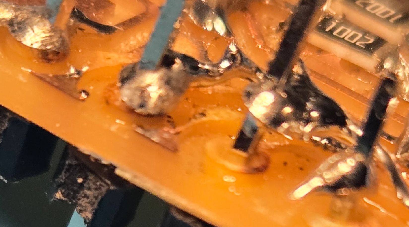
In the end, EVERY single through-hole I soldered ripped it's trace. I think user error is a part of it, but also the horrible nature of milled boards
The closest I got with it was one ripped trace was to have windows recognize that something connected, but it would give a "device descriptor error" and not show up on the com ports in device manager
Quick Update
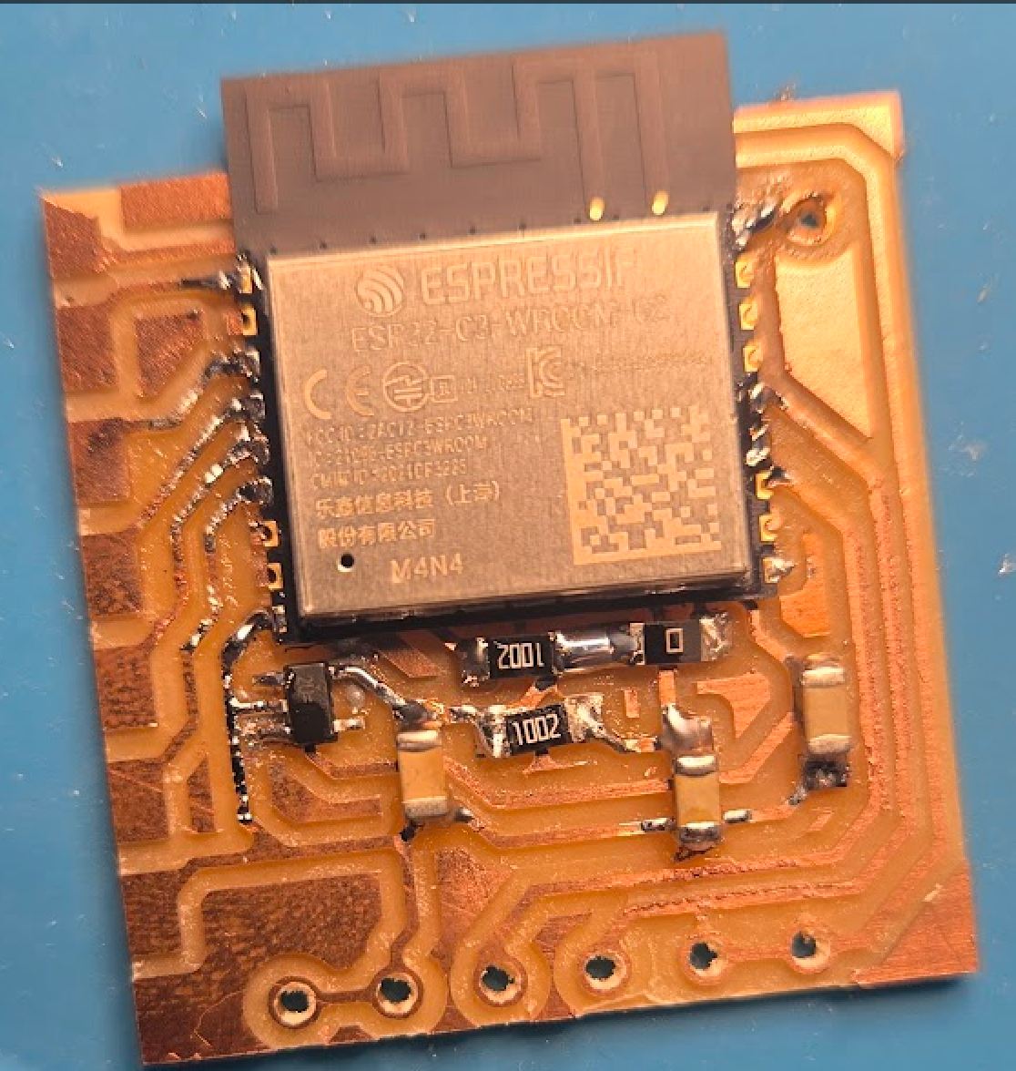
Weeks over, but the PCBs just arrived, so I made a working example. The milled board did do me wrong, as it worked once the professional PCB was used. Im not going to add anymore updates, but you can see in my hero shots what the full assembly looks like. I found soldering on a professional pcb was way easier, and I found that just using solder paste the same way regular solder was used actually worked really well
Hero Shots
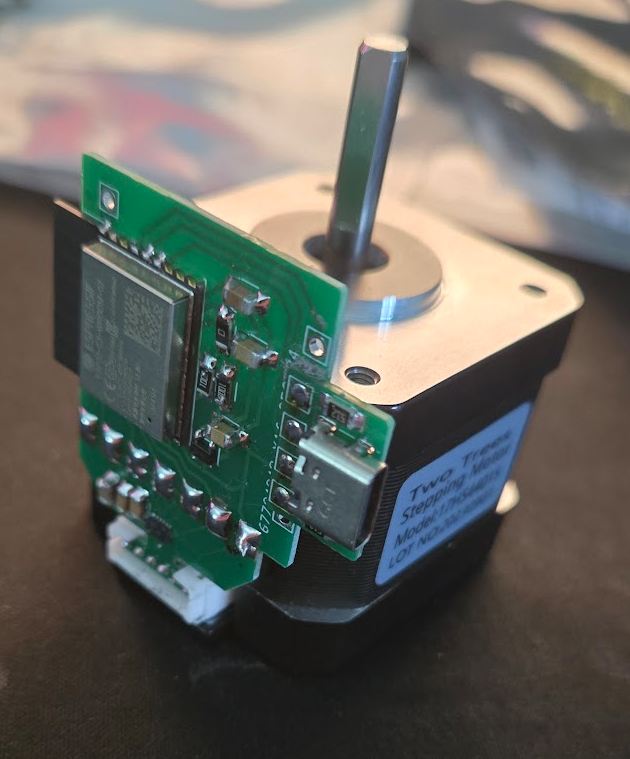
The code wasn't working exactly as intended, and is fixed by my networking week, but theres the shakey output.
Reflection
This week was a series of ups and downs. As with last week, it was another time where I work towards my final fab project, but get nothing tangible done towards the week and have to do a quick project in order to satisfy the week.
Output Devices
Using a servo, although it was hasty, is also part of the requirements for my final project. My project is a camera that can look around, but there is also a shield that can open and close. This is a on/off state. In the game my final project is based off, its bulletproof and oneway for the camera, but I don't need any of that since im designing my project to be really cheap to build for the sake of myself and anybody who follows in my path. Therefore, a cheap way to move a pretty heavy object (maybe 150g of acrylic or similar material). The way the piece will move is revolving around a sphere, so a straight movement with a motor isn't possible. I did look into curved guide rails or similar to use a straight dc motor to move it. Im not planning on doing that since im already overcomplicated with everything else, and another custom board + 3d design would probably be a bit too much at this stage.
Final Fab Work
The main bit of this week, the designing and making of the board, was a reminder in how milling machines have their limits, how if possible, a boardhouses are best, and etching can be a powerful tool for small circuits. Designing the board was really fun, and finally getting it made even funner. The steps between that though were not fun, as they involved a milled board breaking itself multiple times, or a etching almost working correctly. As to the actual board, I think I need a dedicated power supply module for it, but the stepper did spin with a lot of noise. The stepper spinning at all did prove its reason for existing, as it spun entirely off of my laptops usb port, so probably an entire microcontroller and stepper spinning off 600mah
Group Work
I was in the same week that I was in for input week, but 4 weeks later and inputs still not done. Ive done my portion there, so I decided to move over to outputs and just get it done. One surprising thing from it is that even though in theory the led should of used 22 mA, it ended up only using around 16. This goes to show that no circuit is perfect, and even the length of wire or an imperfection of the power supply is adding 40% more resistance to the circuit.
Group Work
As part of the group work, I measured the current consumption of an led and calculated it against what it should of been. A link to that group work can be found here
Design Files
The design files of the boards, as well as the code for the servo motor, can be found here