3D printing and scanning
    Design and 3D print an object (small, few cm3, limited by printer time) that could not be easily made subtractively
    3D scan an object (and optionally print it)
For this week, I wanted to print attempt to print in place a miniature and movable version of my final project,
Scanning
I needed to scan my battery pack into a 3d model, and looked to fab academy graduates for reference. Polycam is very easy to use, but requires precision to get a good result. Polycam annoyingly does have the processing fail, without giving a reason why.
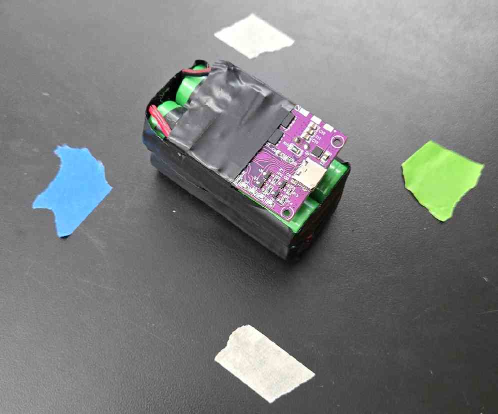
In researching the reason for my first scan's failure, I found that too many photos could overwhelm, and I needed something that would be kept constant and easy for Polycam to track. upon learning this, I used different colored tape to mark out constant tracking dots
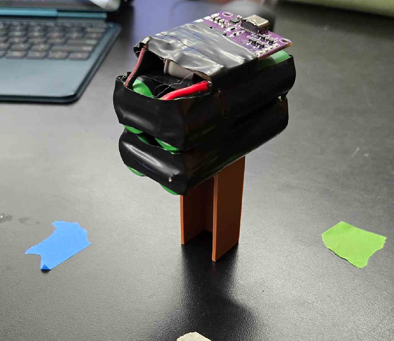
This setup resulted in my first working scan, but I still had a really obvious issue, the bottom of the battery was not visible. This, compounded with the other issue of the shadow acting like a hole, which would result in a bad scan. I fixed this by finding a random 3d print, and setting the battery pack ontop of that, as seen below
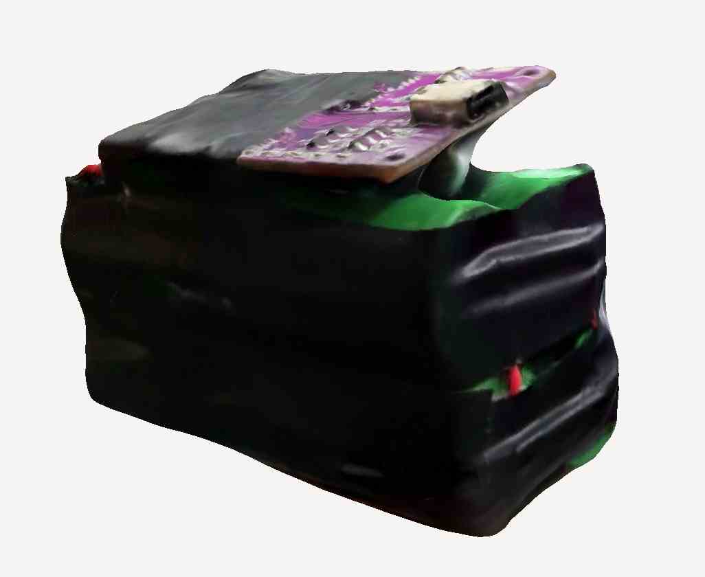
After successfully scanning, I was only able to output as a glb from Polycam, but easily found an online converter to change it into an stl. this stl is attached inside the design files at the bottom of this page. the link to the file stored on polycam servers, which probably won't last too long, is here. I was impressed with its detail, especially with the 1206 components on the board, and even the pins on the usb-c connector. An issue with the well scanned version is that it does not have a base, but using fusion 360's built in mesh repair tool simply connects all the missing parts to form a flat plane on the bottom, and other software would probably preform similarly.
Additive vs Subtractive
For my 3D design, I'm designing with making something through additive processes in mind. Additive processes are anywhere where material is added to make something—the easiest example being a 3D printer, which adds material layer by layer to build complex shapes.
Subtractive manufacturing is the other way around—removing material in order to make a shape. The easiest example of a subtractive process is a milling machine, which cuts away from a solid block to reveal the final form.
Additive manufacturing allows for:
Unique shapes: Internal channels, overhangs, and lattice structures are easy to make.

Less waste: Since you're only adding what you need, there’s less leftover material (if designed right)

Design freedom: with the power of supports, virtually anything can be made
Subtractive manufacturing allows for:
Smooth: additive adds material, but commonly creates "layer lines" that don't look good, reduce strength, and make a rough surface.
some additive processes are able to avoid this, for example resin printers,
but the most common additives are just unable to make a surface as smooth as one made subtractive

Big: specifically with wood, the shopbot at all labs allows for humongous builds

Stronger: Since it's made from a solid block, the final piece can be structurally stronger than a printed one.

No supports: In additive, it builds layer by layer. What if there is not a layer under what you want to build?
then you have to use supports. Supports are designed to have the fastest print time and lowest material cost, and only
exist to hold up a part you actually want. In additive, you need them for mostly ever overhang, but in subtractive as long
as a object isn't too heavy with barely anything holding it up, it will work.
3D design
After scanning my battery, I wanted to start on the 3d printing. In order to reach the weekly goal of making something that cannot be made via subtractive methods, and work towards my final project at the same time. I decided to modify my design from cad week in order to put in the basics of it eventually moving. I started by redesigning the entire head, because it was slightly on the wrong side
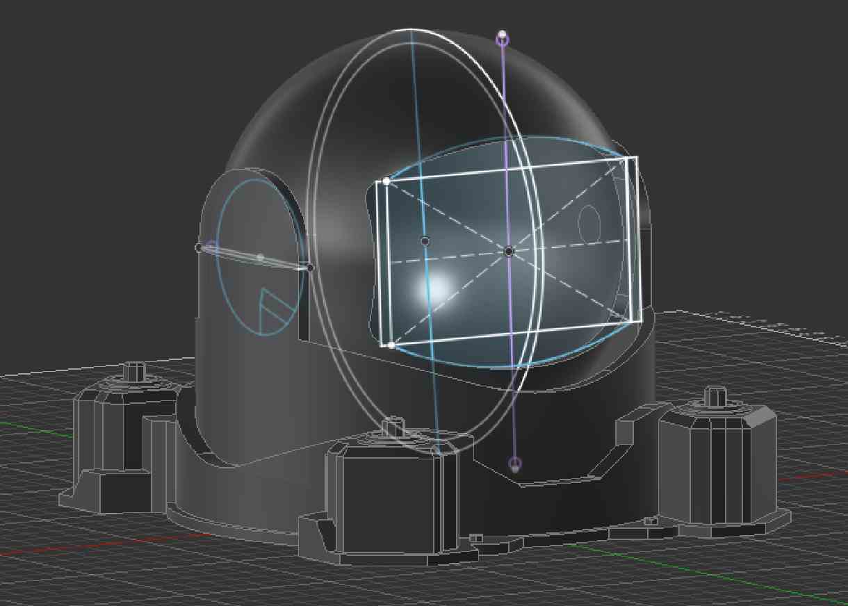
After redesigning the head to make it centered, and the window a bit more visually appealing, I started working from the base up designing mechanisms to make it move. None of these should come anywhere near what it will end up being, but work as a proof of concept.
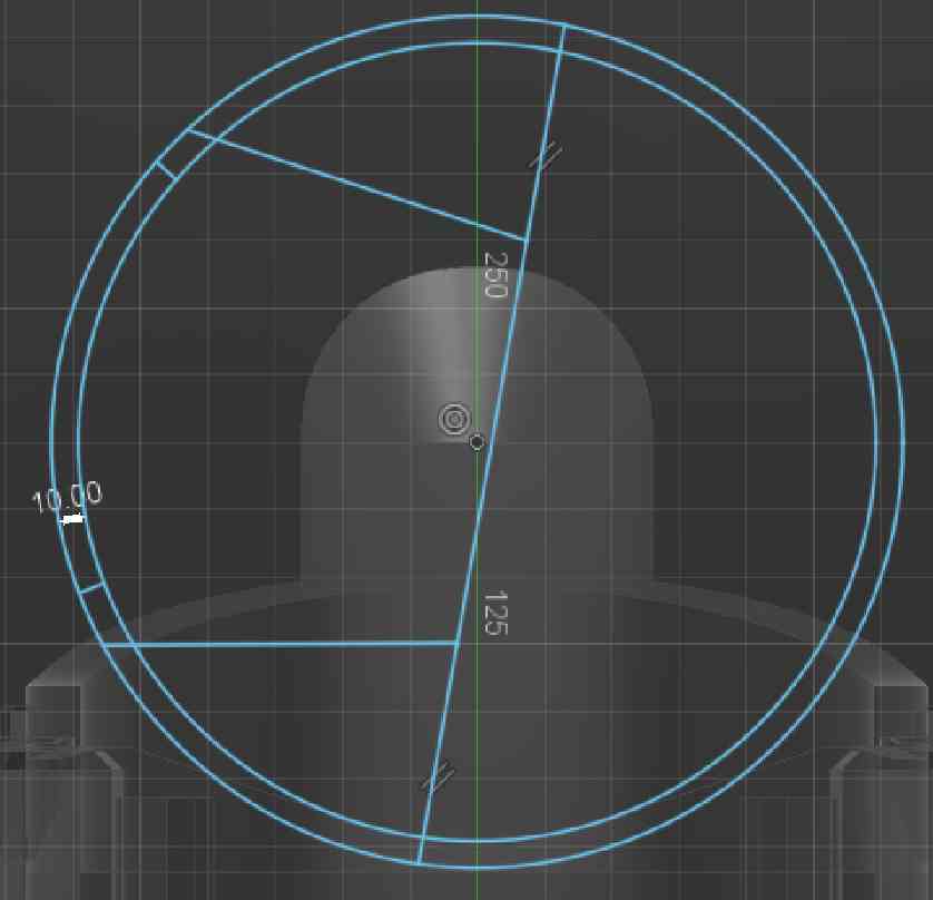
in order to support other moving component, I added a ring on the inside of the base. This ring is meant to support the moving base.
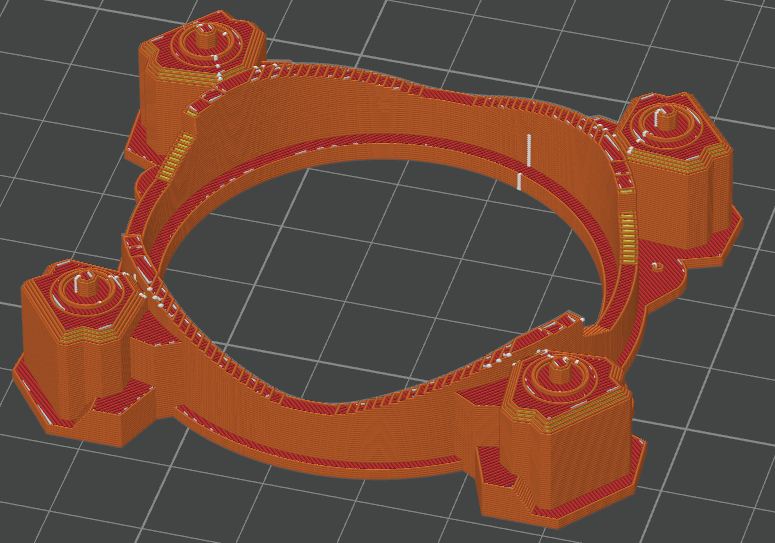
After making the ring on the base, I added 2 legs directly below the arms of the moving section of the base. These arms are meant to rub against the base, in order to keep a stable height.
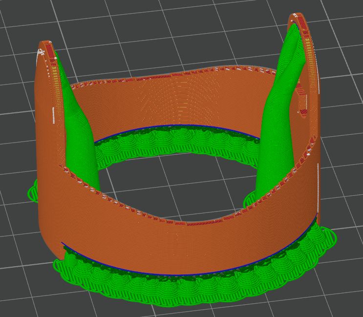
I then started to work interfacing the head with the arms, for this I made an indent in the side of the arms and a bit that juts out on the head, which comes together to hold it steady. This is also the main part of the design that cannot be made subtractively, as hollow shapes are hard to make subtractively, and round shapes are hard but not impossible to make.
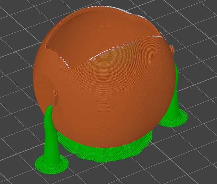
After designing all 3 parts, I printed them out at 15% scale in order to save time. They took about 1.5 hours total, at ultra draft quality. Even at this low quality, the bases fit together well.
I did have an issue with the connection of the head and the arms, but I just scaled the head up to be 5% bigger than the other pieces, and thanks to the flex in the arms it came together.
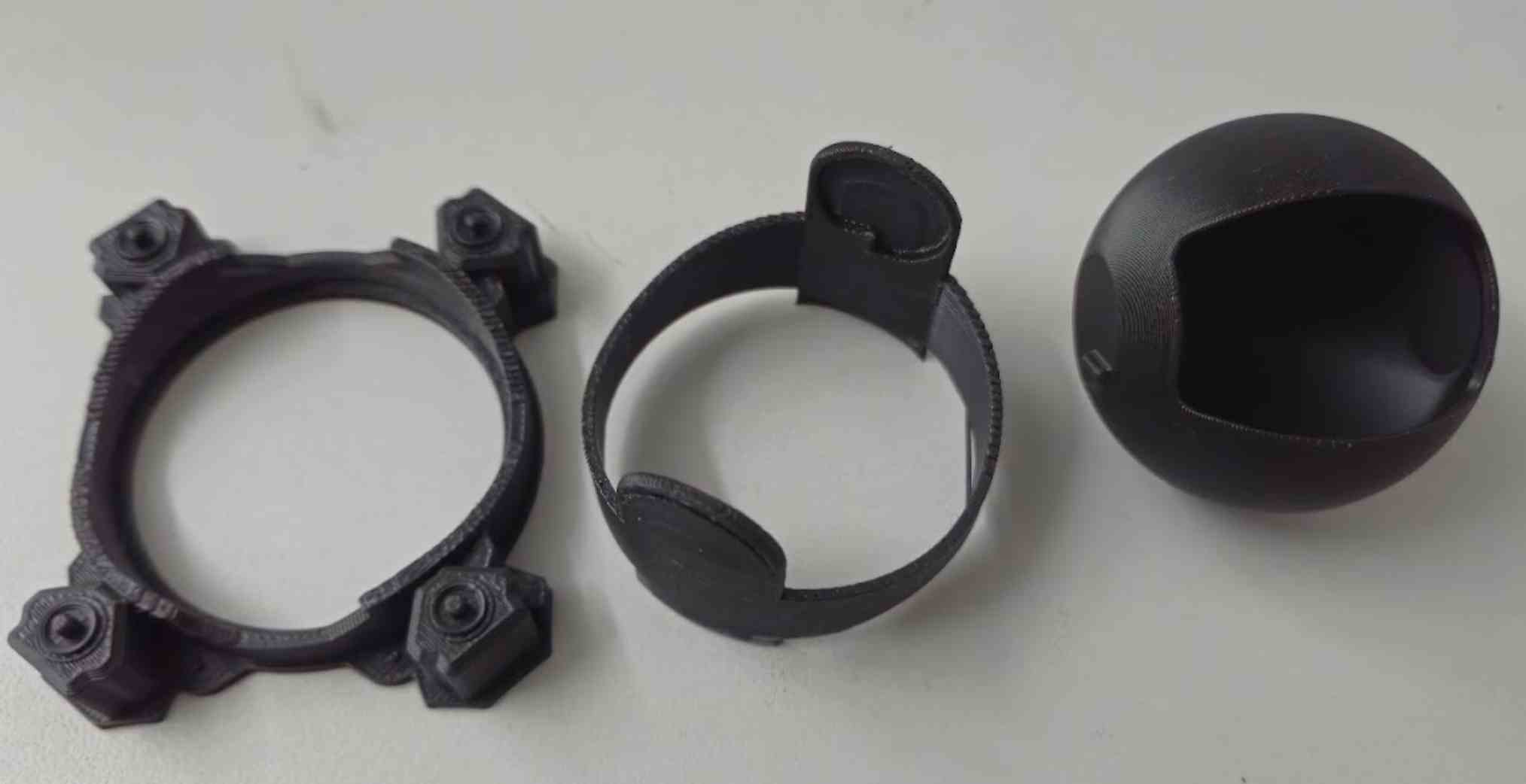
while it does move the way I want it, the head is much too loose, and I defiantly need a better way to hold it on in the final build. I also need to figure out how I am going to make it all, but it will probably end up being the sphere head is exactly small enough to fit on a bambu lab a1 printer or even an x1 carbon, as our lab has one of those with a .8mm nozzle. I also have to fix some small bits that this print pointed out, like the walls being too thin on the arms holding the head
Group Work
For my group, I set up the framework of the site, printed the designs, and made the zip file of all of our designs. My group work can be found here, and a copy of the group work without images below
Overhang Test - Noah Smith
Overhang in 3d printing are the parts of the print that are not directly supported underneath. An overhang can lead to bad print quality, due to the plastic physically drooping, and even print failures. In order to fix overhangs, supports are used. Supports are easily removed parts of a 3d print that are placed directly under overhangs.
The easiest way to test overhang is to create a bunch of them, and look to see how the print turned out. I did this by making half of the gateway arch, with the final being 85 degrees.
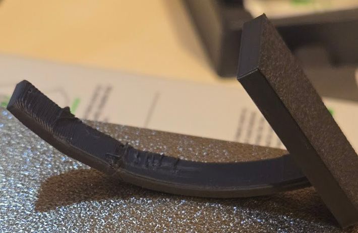
Overall, the final print showed that after about 50 degrees, the bambu a1 mini started to struggle, and leave minor print artifacts, and at above 70 degrees it would have major flaws.
Reflection
Scanning
Scanning was really fun honestly. The only bad thing was that it failed like 7 times, but when it worked, it was a really good scan. I was super impressed with its ability to see the bumps of each resistor on the pcb. My phone doesn't have lidar or any of the fancy distance measuring things, so that was pure photogrammetry(understanding 3d from a bunch of 2d photos) making it all work. I did go on to make a case for the battery, much later on, thanks to the scan.
Designing & Printing
the changes I made to the design were not that big, and I am certain the head to neck interlock will be changed. The base interlock might not be, or more likely will be slightly changed, as I really like how it can be lifted apart. I also had to keep in mind support usage, which is why I ended up printing the head the way it was. Also, just seeing the intricate details I slaved over in week 2 was a really fun experience, and overall it reinforced why 3d printing is king for quick 3d prototyping. I plan on using 3d printing for the entirety of my project, with the exception of my faceplate, which I hope to use milling and casting to make some clear object.
Group Work
It's still amazing to me how well the overhang worked. 80 degrees was almost perfectly intact, and would definitely still work for a part. Looking at my other groupmates, the bridging was also incredibly good results, with a 30mm bridge not failing, and seemingly all it did was make the chance of it failing higher. This was printed on a bambu a1 mini that ~~hasn't seen alot of print time~~ didn't before see alot of use.
Design Files
all 3 parts of the camera, as well as the 3d scan files, can be here