Input Devices
This weeks task was to measure something: add a sensor to a microcontroller board that you have designed and read it.
Scale
In week 6 I designed a board to interface with 2 hx711s for a non fab project I was working on. Luckily for me, the board I ordered arrived this week, so I was able to to use it here. I describe the electronical side in my week 6, so check there for all of that, but here im going to describe the interfacing and code.
Library
When Sparkfun releases a library, you listen. They have a great library for the hx711 here. That entire page is their guide to use their specific board, and was the guide I used while doing this. Also, as I touched on while designing this, my design was based off their board design that they had linked on this page.
Communication Protocol
The HX711 uses a 2 wire protocol, that is incredibly similar to I2C. It uses a Data pin (DOUT) and a clock pin (CLK) just like I2C. these two pins allow for messages to be sent and received.
In Code
This means that the code has a very similar to i2c initializer. instead of wire.begin(data, clock) for i2c, here the library that everyone uses is scale.begin(data, clock).
For a much more general example with the boards that are commonly available (amazon, aliexpress, etc), look to sparkfun's documentation of their version of those boards here. If its shaped like that board, it will work the same as that board
My Code
My code was made following their design guidelines, using their example. The only real place mine is different from theirs is the pinout, which was pins 6 (data) and 7 (clock). Their code worked flawlessly, and was structured at runtime to calibrate (find out what 0 weight is by putting no weight on the scale) and then continuously reporting the value on the scale
Hero Shot
Time of Flight Sensor
For my first take at input week, I also used a TOF sensor. I used it with a breadboard however, but I decided to keep it in here.
Device Choice
I wanted to use a time of flight sensor since it is very "visible" for me, and I have experience with the more advanced versions of it. Specifically, I have used the multizone vl53l7cx in the past, and have been on the emailing list for the vl53l9ca, and used the old vl53l1x as that is what my lab had at the time. Specifically, my lab had the Adafruit vl51l1x breakout board All of these different sensors are of the same series, being the STM time of flight sensor series, and they all do the same thing. They really accurately measure distance. There are virtually no drawbacks with them, they are small, highly accurate, low power consumption, and multi zone. Multi zone, is most simply explained by comparing it to a camera, the vl53l1x is a 1x1 zone, so it measures 1 distance, the vl53l7cx is 8x8 zone, so it measures 64 distances, think of them like pixels. The unreleased model, the vl53l9ca will be 42x52 zone, so it will be a fully fledged depth camera
Usage
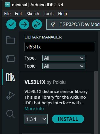
Using a time of flight sensor, especially the vl53 series, is very easy. any sensor in the series, they usually have a polulu breakout board, for example the vl51l1x, which also means that polulu has created a library for that sensor. Those libraries can be found inside the library manager in all arduino IDEs 2.0 and onwards, and once installed includes example sketches
After downloading the library, it installs examples. For my purposes, I used the continuous example.
Wiring
As I spent most of this week working on output devices, I used a breakout board along with my [custom esp32-c3 board] that I designed before Fab academy. I did this because the board I designed last week as made for only one thing, and that was being the unrefined version of the logic of the stepper motor driver im designing for next week.
The pins I used for this were
3.3v: top left on my custom board, the specific breakout board I used uses level shifting, but the vl53l1x natively is for 3.3v devices GND bottom left of my custom board IO0 top right of my custom board, used as SCL IO1 top left of my custom board, used as SDA
Code Fixes
the example is not perfect, and needs to be modified, especially for a esp32-c3 chip. The esp32-c3 does not have set i2c pins, you have to define them as you enable i2c. You can do this by modifying this line
Wire.begin();
to
Wire.begin(SDAPIN, SCLPIN);
in my case, this was the 2 top left pins of the board, io0 for SCL and io1 for SDA, making the code
Wire.begin(1,0);
After uploading the code, I ran into a problem. This problem, which i've run into nearly every time I use that custom board, just requires me not to forget it. It was that I had not turned on USB CDC on boot, therefore disabling the built in serial converter while the board was running my code. This caused a lot of confusion, but after remembering it was an easy fix by changing it in tools -> USB CDC on boot Enabled
Processing
After reading the raw data, I wanted to go further. This is where a program called processing comes in handy. Through it, I can read data from the serial monitor and visualize it with graphs or 3d simulations. I have no experience with processing, but it is very identical to arduino code, even including the annoying fact that the sketch has to be stored in a folder and cannot have spaces in its name. It basically works like arduino in reverse, instead of making code for the microcontrller, the microcontrller will send data that the processing sketch processes in some way. This is done using the processing.serial.* library, which enables processing to read from the computers COM/DEVTTY ports. Processing is very easy to understand even if you know nothing, as it is essentially:
Define a object, E.G. box(100) makes a cube 100x100x100
Move that object, Translate(x,y,z).
Im not a good explainer, but I hope this gets the jist. You just say how to move something, using very basic commands, and it moves it.
Hero Shot 2
Reflection
HX711
I've been working on that project for a while for a friend, but the most annoying thing was the amount of wires going everywhere. The board fixed all that, and this code prooved it worked.
Time Of Flight
Hardware
Im a fanboy of time of flight sensors. Just seeing how a sensor can (very accurately) measure distances up to 2 meters away just makes me want to make something with it. As I talked about above, I am on the mailing list for when the vl53l9ca comes out, and I will certainly find a project I want to make around the sensor. For some projects, you have something you want to make and you have to figure out how, and for others, you have something really cool that you want to make something with. If anybody else is interested in it, I found in a thread, that a STM employee said that the vl53l9ca would be released around the end of this year (2025). That sensor isn't just good for the high zone count, it also promises incredible ranges (up to 10 meters!) and highly improved accuracy in ambient light (one of the drawbacks of time of flight sensors)
The Software
The Arduino IDE is a jailcell for me. For some reason, on both my decent laptop and blazing fast computer, compiling a sketch for the esp32-c3 takes at least a minute. When I installed platformio on my computer (it does not work on my laptop), I found that it could compile in less than 10 seconds. I want to escape it, but the ease of use, and just the fact that my laptop cannot run most other IDE's due to it being windows on arm, has me chained up. As for the code specific to this project, it was really good, as polulu releases really good libraries for any boards that they make. Processing was also easy to work with, as its very easy to wrap my head around, and I would describe the code as very human readable. Also, one of my instructors, Dr. Taylor mentioned before how he used Processing alot previously for his final project, so looking at it helped me wrap my head around it.
Group Work
As part of our group work, I made a really small temperature sensor using a resistor. A copy of that writing can be found below, and a link to my group page (once its merged) is here.
Analog Signal - Noah
For an analog input device, I used a thermistor setup to act as a voltage divider. A thermistor is a resistor that changes resistance based on temperature. A voltage divider is a circuit that takes an input voltage, and splits that circuit into 2 paths based on the quotient of 2 resistors. The formula for a voltage divider is Vout = Vin * (R2 / (R1 + R2)). In our case, the vin was 3.3v, and the vout was any number between 0 and 3.3v, with lower meaning a higher temperature.
Analog PCB design - Noah
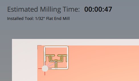
as our lab only had surface mount thermistors, I designed a small circuit consisting of 3 pads, that being vin, vout, and ground, and 2 resistors, a standard 10k resistor and a thermistor that maxed out at 10k ohms. This board was designed to be used with a 1/32in bit to mill faster, and was designed to use pads instead of through hole for interfacing
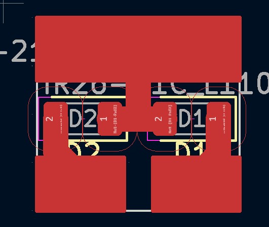
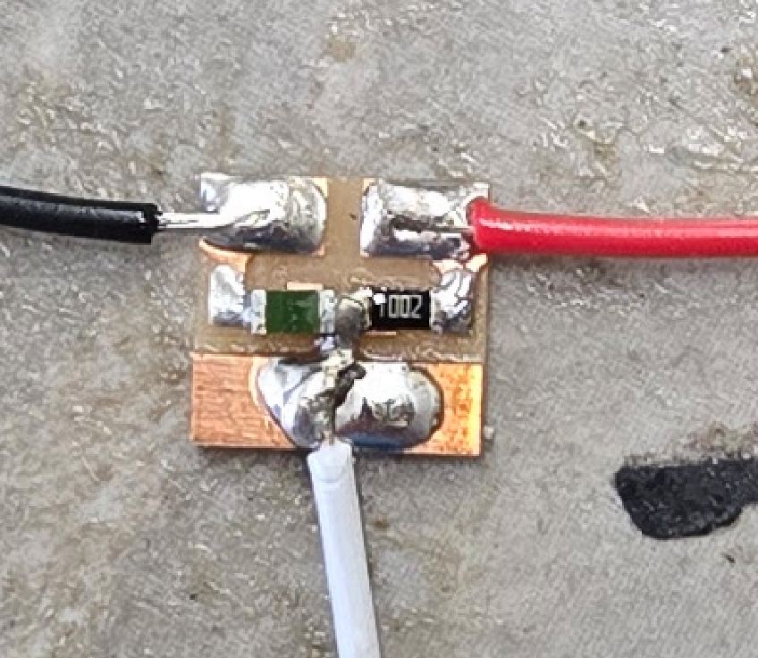
After milling the board, I soldered a 10k resistor to the left side, closer to the vin pad, and a thermistor to the right side, closer to the ground. I also soldered on the wires, a red for Vin, white for Vout, and black for ground
Analog Code - Noah
For testing it, we used a esp32-c3. The most important feature of the chip for measuring an analog signal is the resolution of its ADC, or analog to digital converter. The esp32-c3 is very strong for this, with a 12 bit (4096 levels). This is the same as the pi pico, but 4x better than the arduino uno's 10 bit (1024 level) resolution. Because of the increased adc resolution, the sensor is able to detect 4x more steps in temperature vs the uno.
// Analog Signal - Thermistor Reading with ESP32-C3
const int analogPin = 0; // GPIO0 (A0 on most ESP32-C3 dev boards)

void setup() {
  Serial.begin(115200);          // Start serial communication
  analogReadResolution(12);      // Set ADC resolution to 12 bits (0–4095)
}

void loop() {
  int rawValue = analogRead(analogPin);                // Read analog value
  Serial.println(rawValue);                       // Print voltage to 3 decimal places

  delay(250);                                          // Wait before next read
}
As seen in the video, as my bodyheat, which is hotter than the ambient temperature touches the sensor, the themistor increases its resistance therefore routing more voltage to the Vout pin
Reflection
Individual Work
I've used the vl53 series in the past, mainly the most advanced at the time, the vl53l7cx which had a resolution of up to 8x8 and a still industry leading fov of 60 degrees in each direction. Going back to the vl53l1x actually was refreshing, as the vl53l7cx was really inaccurate, especially when in ambient lighting involving sunlight, which is a pain point for all of STM's time of flight sensor
Group Work
Honestly this little thing has me more proud than my actual individual work. It really is just 2 resistors and 3 pads in as small a space as possible, while also designed for no bit change (1/32 inch bit the whole way) and easy soldering with large pads. If I could go back and change anything on that board, I would make the signal pad smaller, as with such a big pad the heat gets spread out really fast which results in the solder not melting well.
Design Files
The design files can be found here
While this week does not have a lot to it, I also included the design files for the PCB's I was making for output week, as a time capsule more for myself than any readers, and to show I wasn't just lounging around for most of the week (although this was during my schools spring break)