Computer Controlled Cutting
Group assignment:
- Do your lab’s safety training
- Characterize your lasercutter’s focus, power, speed, rate, kerf, joint clearance and types.
- Document your work to the group work page and reflect on your individual page what you learned.
Individual assignment:
- Design, lasercut, and document a parametric construction kit, accounting for the lasercutter kerf, which can be assembled in multiple ways.
- Cut something on the vinyl cutter.
Designing my vinyl sticker
For my vinyl sticker, I wanted to create a funny looking dog called scoobert through layering the sticker.
finding the image to use
This was a challenge for scoobert, as I went through multiple images that each had their own flaws. The problem with multiple of the images was that scoobert blended in too well. His grey and brown fur was often too similar to the table, which would lead to problems when tracing him or splitting him into multiple colors. For example, this image of scoobert 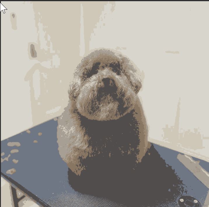 has an issue where, when he is traced, it would assume the black table he was sitting on was a part of him. In order to fix this issue, I found an (online background remover)[https://www.remove.bg/] that had something similar to the magic eraser in new phones, and it allowed me to specify which parts of the background I wanted removed. After removing the background, I ended up with this image.
 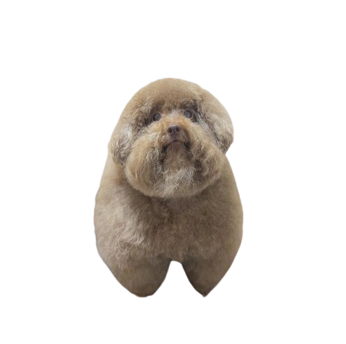 This was not without flaws, as his right paw is less rounded, but I decided to accept it because it worked besides for that.
Tracing the image
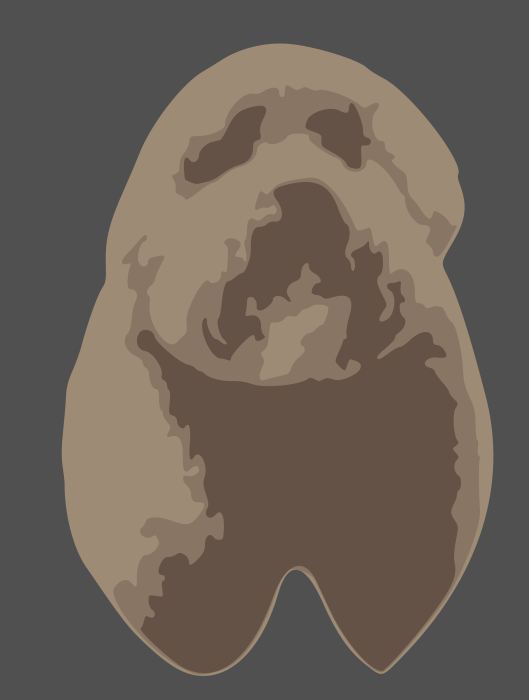
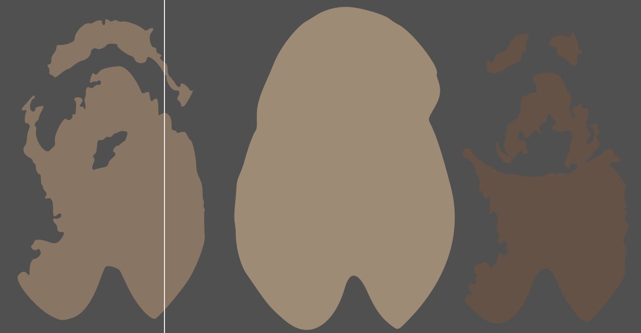
Once I had the image, I needed to trace it into multiple pieces in order to vinyl cut it. I found that at 3 colors he was still recognizable.
The settings I used for the trace were: Multicolor Scan, Colors detection mode, 3 scans. Although I tried changing the other settings, which would of probably lead to a better result, they just didn't work on my system, which is another loss for windows on arm.
Tracing and test Cutting
After tracing, I went to find the material to use. 2 of the 3 colors were really easy to find, but the third was both hard to find, and once I found it it was also barely enough material for a single cut. In order to prevent that cut from being a failure, I decided to do a test cut first. Thanks to the fact that I managed to get one of our labs newer vinyl cutters, I was able to quickly cut out a test. our labs vinyl cutters only work with silhouette studio, which is not the most advanced software, and lead to another problem. In scanning the different stages of scoobert into silhouette , I found that the darker side was unable to be scanned, and therefore had to change the colors of him in order to fix it. 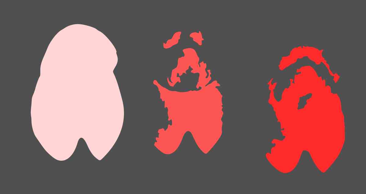 The only redeeming quality of silhouette studio is that it is made for a 2 year old to use, with beautiful buttons like a butterfly icon for its trace. This also means that it is very easy to work with, and if the trace actually works gives clean results.
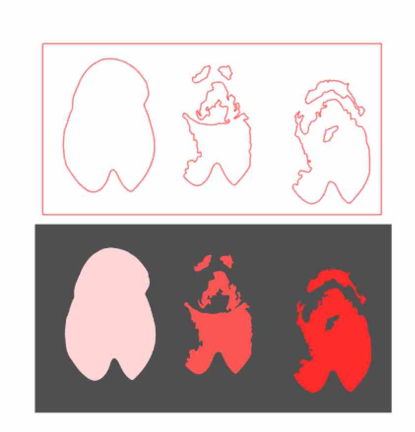
After tracing, I cut scoobert out on a random sheet of purple vinyl that I found. Going with the theme of silhouette studio being made for a 2 year old, setting the cut settings is very simple. 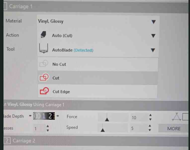
I only needed to change the top field of this image, to make it Vinyl, Glossy, which changed all other settings to be the best for vinyl glossy. While their software isn't the most advanced, it is a pleasure to work with when it does work.
Weeding
Weeding is pretty simple, you just pull out the gunk you don't want while keeping the stuff you do. With a well calibrated vinyl cutter, like the one I used, it is a breeze, but with a not well calibrated cutter, like the one my classmate, Elle Hahn had and will certainly document her experience weeding its cuts.
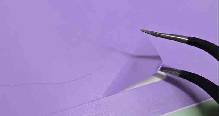
Tweezers always help with weeding, but with such a good cut I could of used my fingernail and got the same result.
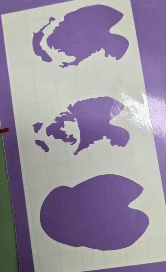
After weeding, I ended up with 3 scoobert shaped blobs, that once color was added would hopefully look like him.
Final Cut
For my final cut, I ran into the issue of lack of materials. The image below showcases what I think is every bit of that shade of brown vinyl we had in our lab 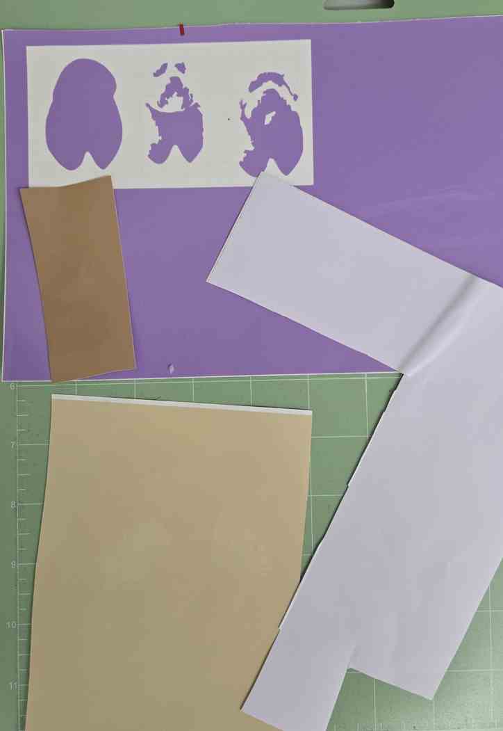
This meant that I had one shot at scoobert. I cut him in three different parts, all on the good cutter. 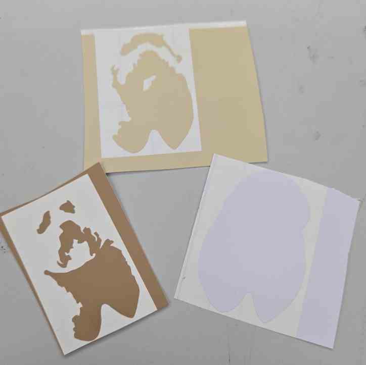
After cutting and weeding, I ended up with all the parts of scoobert, scaled correctly and in the right colors. I then realized they were not the right colors. Specifically, the white shade just wasn't the color that he actually was. 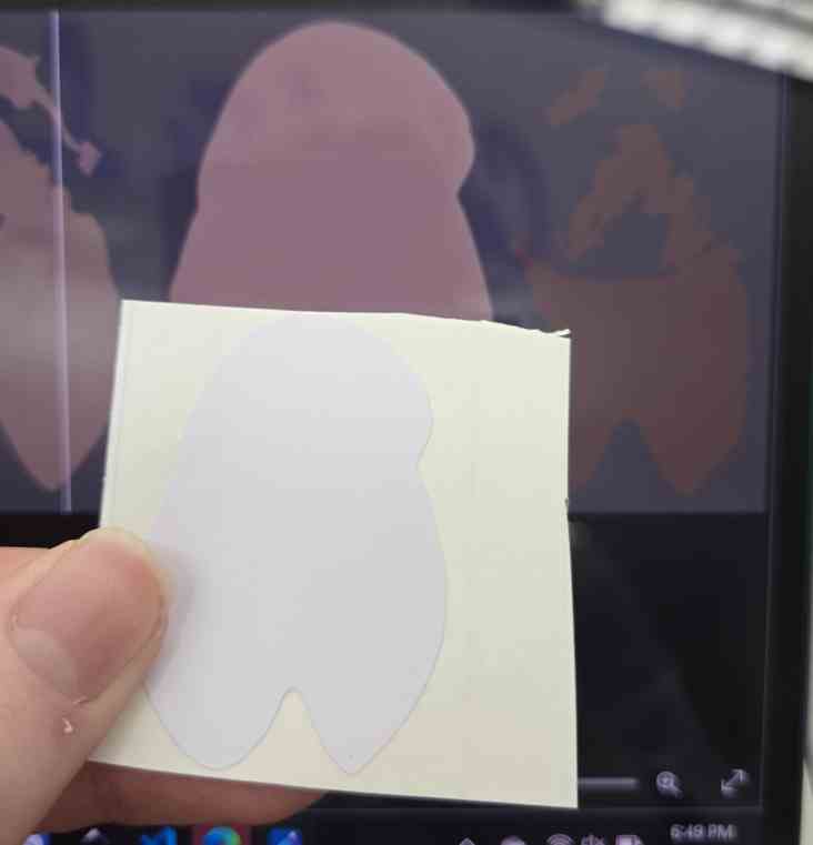
It was much too white, while I needed a more yellow shade. I sorted through my labs scrap vinyl bins, and in the purple box I found a yellow that fit him better 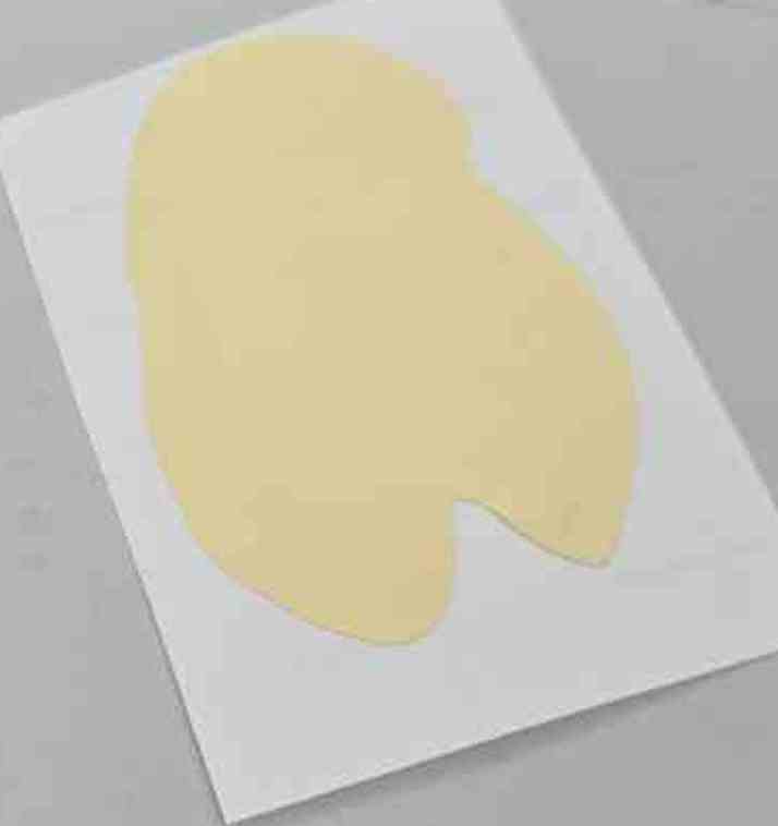
I cut the good color to replace the old body
Assembly
Making a multi layer vinyl is an experience, usually a good one but devastating if done wrong. I did it wrong. It went fine for the overlapping the first two 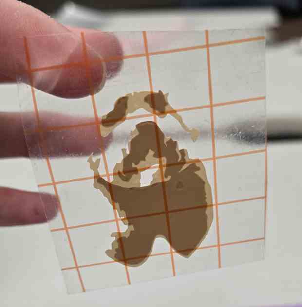
which magically were lined up perfectly by hand. However, on the third one, I put it way too high 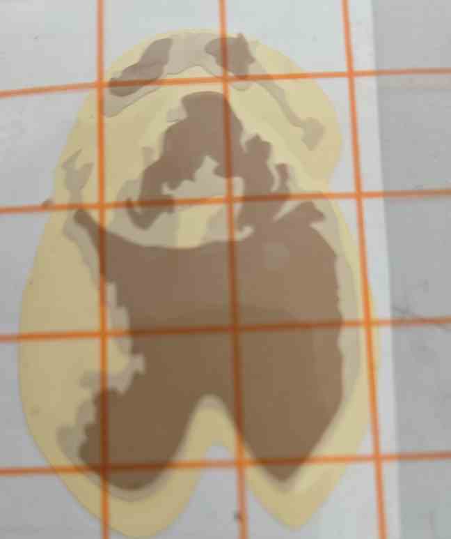
Fixing this was an unfun experience. I basically peeled apart the the two stickers, paying attention to not rip anything. This is much more stressful than it sounds, with a small mistake requiring a restart. This also compounded with the fact that I did not have enough vinyl to cut another top layer, meaning that there was no restarting if I made a mistake. In the end, I successfully peeled them apart 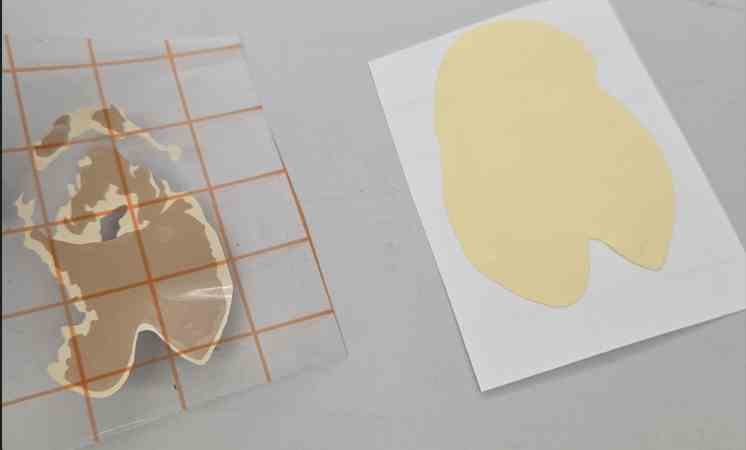
After transferring everything out into the transfer tap, I was able to put it onto the wall of glory 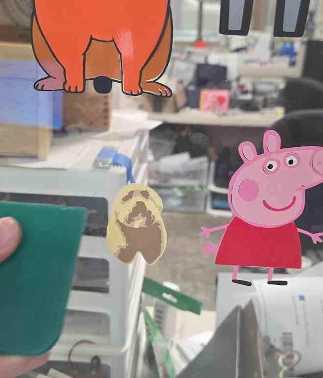
. The only thing im sad about with this is that I feel now the backing color is still not perfect, its just a bit too bright compared to the reference image. This helped me learn alot about the tracing feature in both inkscape and silhouette studio, which will always be helpful to future projects. it also taught me which vinyl cutters in my lab are better at cutting, and important lessons in how to fix my mistakes in multi layer vinyl cutting.
Parametric construction kit
Laser Cutter Safety
Before starting the design, I had to go over safety. Im lucky that my lab allowed me to start using the laser cutter starting in 7th grade, which allowed me to be very comfortable with using them safely. The first time I used it, it was to make a simple box, and I documented on google slides found here. Im also lucky that my lab has really good laser cutters. These laser cutters account for alot of safety features for us, like having "air assist" systems that ensure smoke never builds up, and automatic interlock systems so that we can never have the laser on while the door to the enclosure is open. Also, laser cutters are just much less scarier than other cnc machines like shopbots, because there is much more safety measures to prevent even the most new user to use it without blowing up the entire machine.
General rules
- Maintain appropriate airflow
- Our laser cutters have built in fans that keep smoke from building up in the enclosed chamber
- Never Leave the laser unattended
- Especially for cardboard, laser cutters can just randomly set your material aflame even with the right settings. Make sure to keep constant attention on the material and be ready to emergency stop
- Keep the area clean
- Make sure to never leave any materials, especially flammable, inside the laser cutters enclosure.
- Use the correct materials
- The only materials my lab ever uses is cardboard, cardstock, wood 1/8in, wood 1/4 in, and acrylic. We generally avoid all other materials because they are prone to either making toxic fumes or reflecting the beam and destroying everything.
Design
In order to fully understand what the requirements of this project were, I looked towards my brother, Graham Smith's documentation for this week. I was planning on using fusion 360 already, as it was the only design software I know that has the word parametric associated with it. He has an image on his page, that mentioned the parameters feature. Researching it further, I found this article going over all of its features, and realized how I could use it.
For my take on the parametric construction kit, I was inspired by something very dear to me, my spine. The plan in my head was to create rails that could have smaller pieces attached. The best analogy for this is probably aluminum extrusion in 3d printers, which make up the main frame around which the electronics are assembled.
I decided on a block with finger joints, and each gap in the finger joint would be able to fit another block or a spine piece. The first design was a simple block, with the spine being a rectangle. 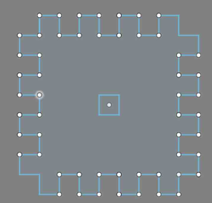

Cutting
Laser Cutter Choice
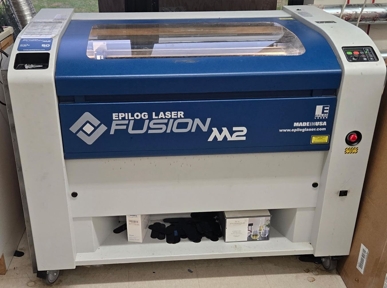
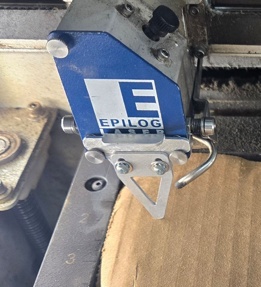 Before cutting, I had to choose which cutter I used. I decided on the oldest one in the lab, solely because it had a really accurate manual focus(seen on the right) and it seemingly has better kerfs that the others. The others are more modern, cut faster, have better safety features, and a feature that makes the, 10x better than the one I chose. The better feature is a camera built into the cutter, that allows for really easy cut positioning. The laser cutter I used was the Epilog Laser Fusion M2, specifically the 32 inch variant. This is a really good laser cutter, but held back by the fact that it was released 11 years ago. According to it's owners manual, It can cut cardboard at 20-30 inches per second, and has the capability to account for all of the features that the better cutters have, but the cutter at our lab doesn't.
My labs specific Epilog Laser Fusion M2 specifications
- Build Plate Volume: 32" x 20" (812 x 508 mm) work area
- Laser Options: 50W C02 laser
- Fast: Up to 120 inches per seconds, only really applies when cutting cardboard
- Materials: Cuts and engraves wood, acrylic, and cardboard
- Connected to the computer through USB
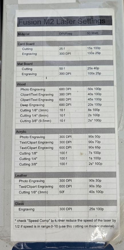
Once I had my first design, I needed to import it into coreldraw from fusion 360. For that, I followed this great tutorial I ran into a problem where I just put in the wrong material depth, causing it to have too big a gap and and nothing fit together. After fixing this, I cut again but ran into a new problem. I was using my labs oldest laser cutter, Epilog Laser Fusion m2. This doesn't have some of the advanced features of the other cutters, like reliable auto focusing, camera based design placement, and easy settings. Most of these settings were just annoyances, like the manual focus being really easy and placement just kind of being a game of chance, but reflecting back I think I was cutting with too low speed and too high frequency for all of my cuts, which might of contributed to me needing to set my kerf so high, and my multiple failed cuts from the kerf being too low.
After zoning on the right settings, I was able to make my first successful cut. 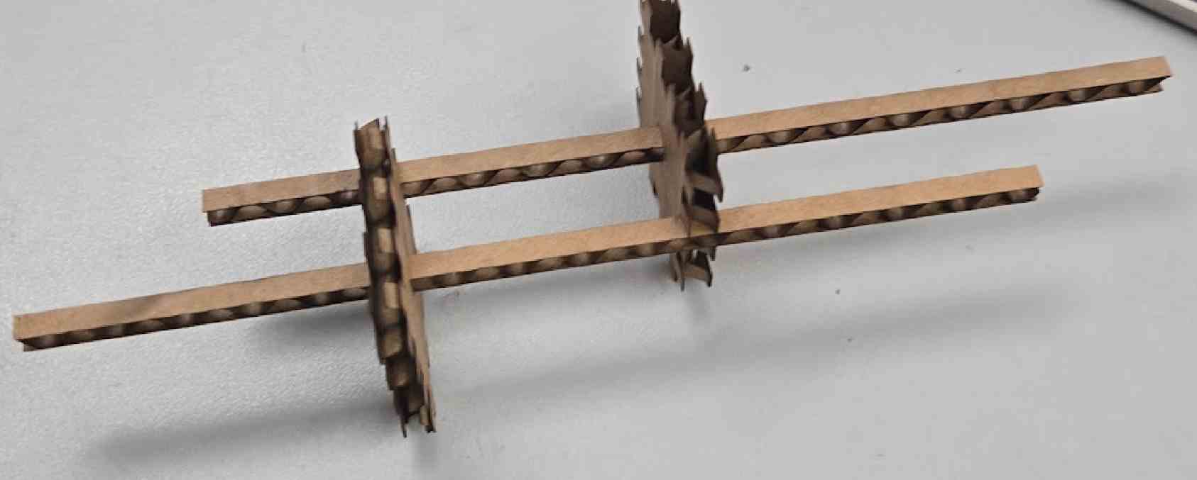
After getting one working spine and block that linked together, I made a couple of the pieces and connected them all. In an advanced test, I detected if they really linked together well:
After the first successful test of it linking together, my instructor suggested I use chamfer in my design, to make it come together easier. I redesigned my box, while keeping it parametric 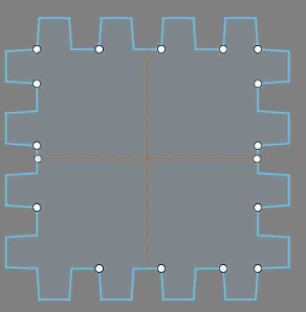
The only problem with chamfers this small, is that I honestly am unable to tell if they are doing anything, and the only way to be able to tell is to find some much thicker material that the laser cutter could still cut through. Here is what it looked like with the (probably) chamfered pieces 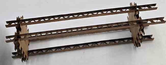
My final parameter table looked like this: 
Through changing the materialdepth (how thick the cardboard was in my case) and the kerf of the laser cutter it would dynamically update to ensure proper fitting between the spine and blocks.
Group Work
All group work can be found on my group site. For my part, I did the kerf and focus, which can also be found below
Kerf
Kerf is the width of material that the laser removes during cutting. It is visible in how thick the line of burn is left after laser cutting. in a perfect world, there would be no kerf, and therefore the cut line would be infinitely thin. We aren't in a perfect world however, so kerf is caused by various factors. These factors include the focus, power, speed, lens and focus. To account for kerf,
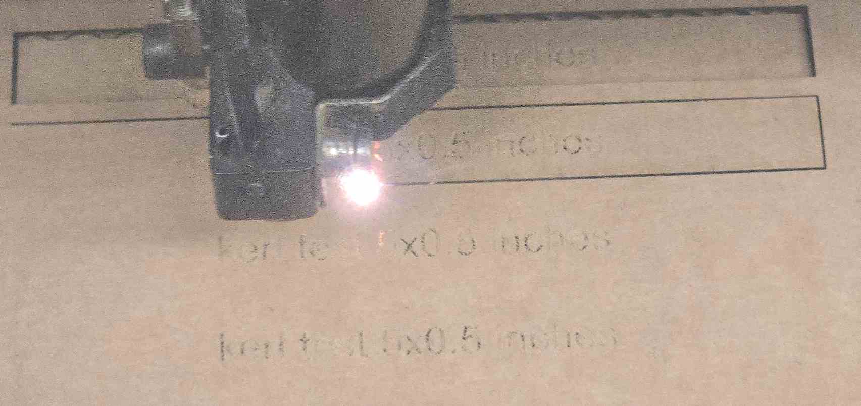
In order to test the kerf, we made 5 cardboard strips that were supposed to be exactly 5 inches. By comparing their real sizes to the size they were supposed to be, we could find the kerf. The caliper that we used could go to 3 decimal places, so accuracy in measurement was not a worry. After checking all 5 strips, we found that the kerf of our laser cutter to be 0.0144 inches. Of course, this is on cardboard, which is known for having a higher kerf than other materials, and A group from last year found that be as low as 0.012 inches for a wooden piece.
Focus
In order to test focus, we first manually homed into the perfect focus, then offset by different amounts to see its effects. We kept all other settings at their defaults, which were probably found by students of fabacademy past. We found that as we got closer to the material, it started producing more flames but the line was thinner. As we got farther from the material, it started cutting more at once and producing more flames. We therefore devices that when the machine was focused right was best, except for when kerf was such a problem that focusing closer would be a better option. For engraving colors, we found that at around .2 inches farther away the black was much more visible. 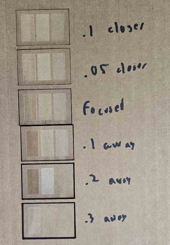
Reflection
This week was an incredible learning experience, not just in using the machines, but also in understanding the nuances of different design and fabrication techniques. From working with the vinyl cutter to developing a parametric construction kit, I encountered a variety of challenges and had to problem-solve in real time.
Vinyl Cutting Reflection
One of the biggest takeaways from the vinyl cutting process was how important image selection and preparation were. Finding an image that would work well when traced into multiple color layers was more difficult than expected. Even after finding a decent enough image, I still had to do alot of preparation in removing the background. Through this, I gained a much better understanding of how software like Inkscape and Silhouette Studio handle vectorization. I also learned the importance of material availability—having barely enough of the brown vinyl added extra pressure to get the final cut right on the first try. The process of layering the vinyl also reinforced the importance of careful alignment, and I now know how to correct mistakes when things don’t line up properly.
Overall, the workflow that I followed here to make the multi layered design is probably exactly what I will follow in the future for any similar project, as it was a really pain free experience once the image was imported into inkscape.
Parametric Construction Kit Reflection
The parametric construction kit was my first real deep dive into Fusion 360’s parametric design tools. Exploring the use of parameters allowed me to quickly adjust my design based on material constraints, which is something I see myself using a lot in the future. I perfectly showed the value of a parametric design by messing up the material thickness multiple times in a row, but being able to change the thickness with only a couple button presses saved me alot of trouble. Also, It taught me the importance of chamfering my edges, as the unchamfered variants were really hard to fit together vs the chamfered.
Overall, parametric design using the modify panel is something that I plan to use in the future, and will be extremely helpful in testing moving parts of my final project.
Design Files
All design files can be found here, taking up a total of 270kb
