System Integration
this weeks assignment was to Design and document the system integration for your final project
Integration Overview
The main issue of clean integration in this project was: "Where do the electronics go?" The answer to this was to create pockets wherever possible to hide the circuits, wires, battery, and even motor. All 4 corners of the base were hollowed out for a specific purpose, and the head was completely hollow both for weight/cost saving and to provide an easy place to store its electronics.
Base Motors
The main brunt of this week was figuring out how I would embed my motors into the 3d design. Due to this being a really big but hopefully hollow and light, I wanted to find a way to store that stepper in some enclosed area. The only area that really could be possible is one of the legs on the corner of the base or inside the base itself
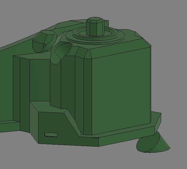
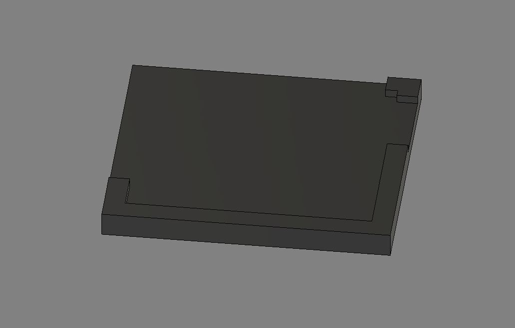
Option 1
I started by trying to hide the stepper in one of the legs, as seen below
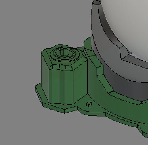
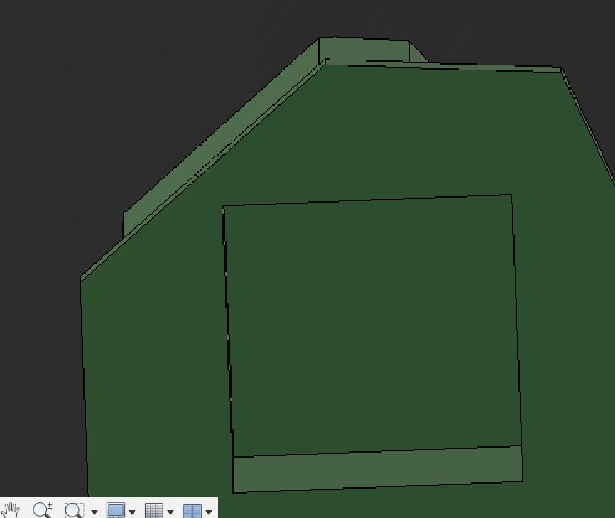
After getting that far, I realized that combined with the driver mounted onto the board, then space would become so annoying to work with that I decided against probing this further.
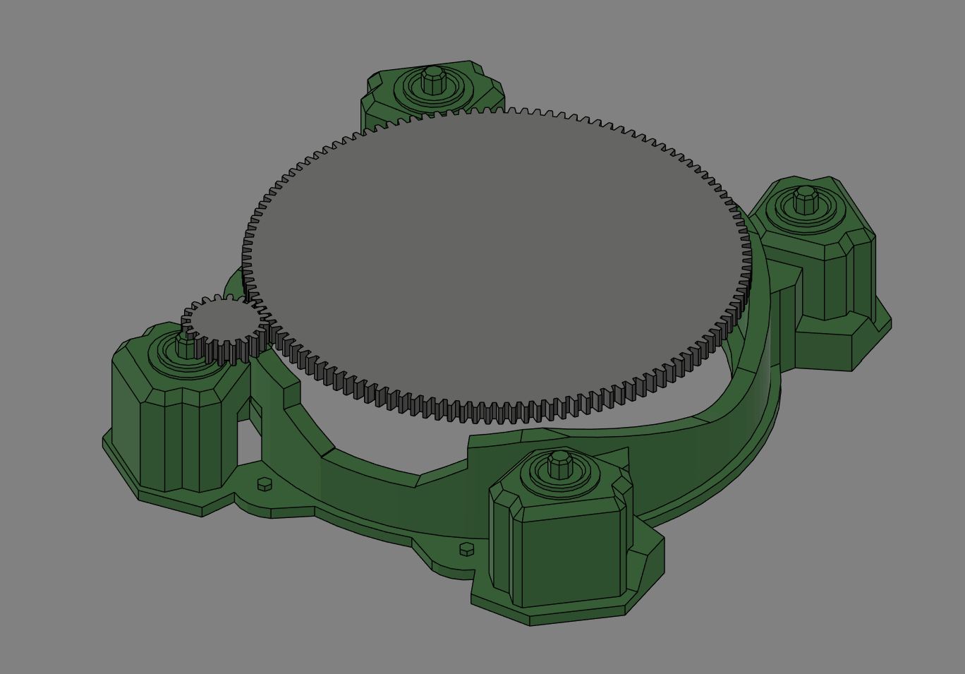
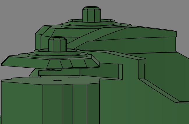
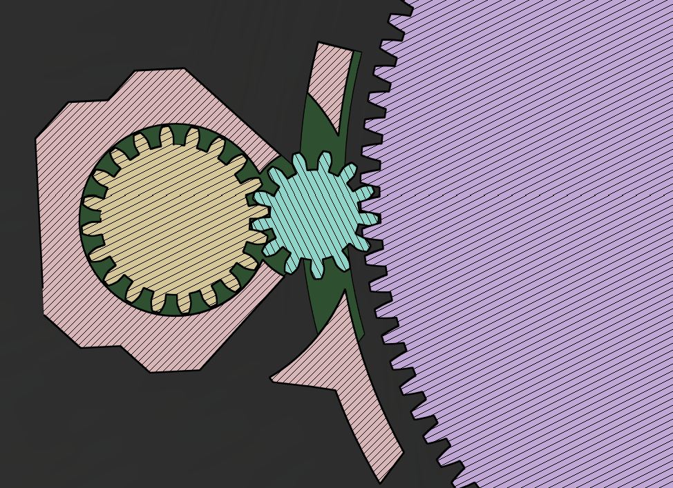
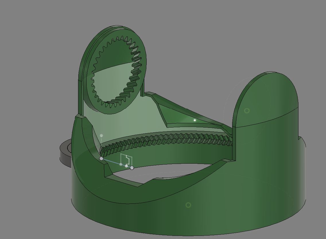
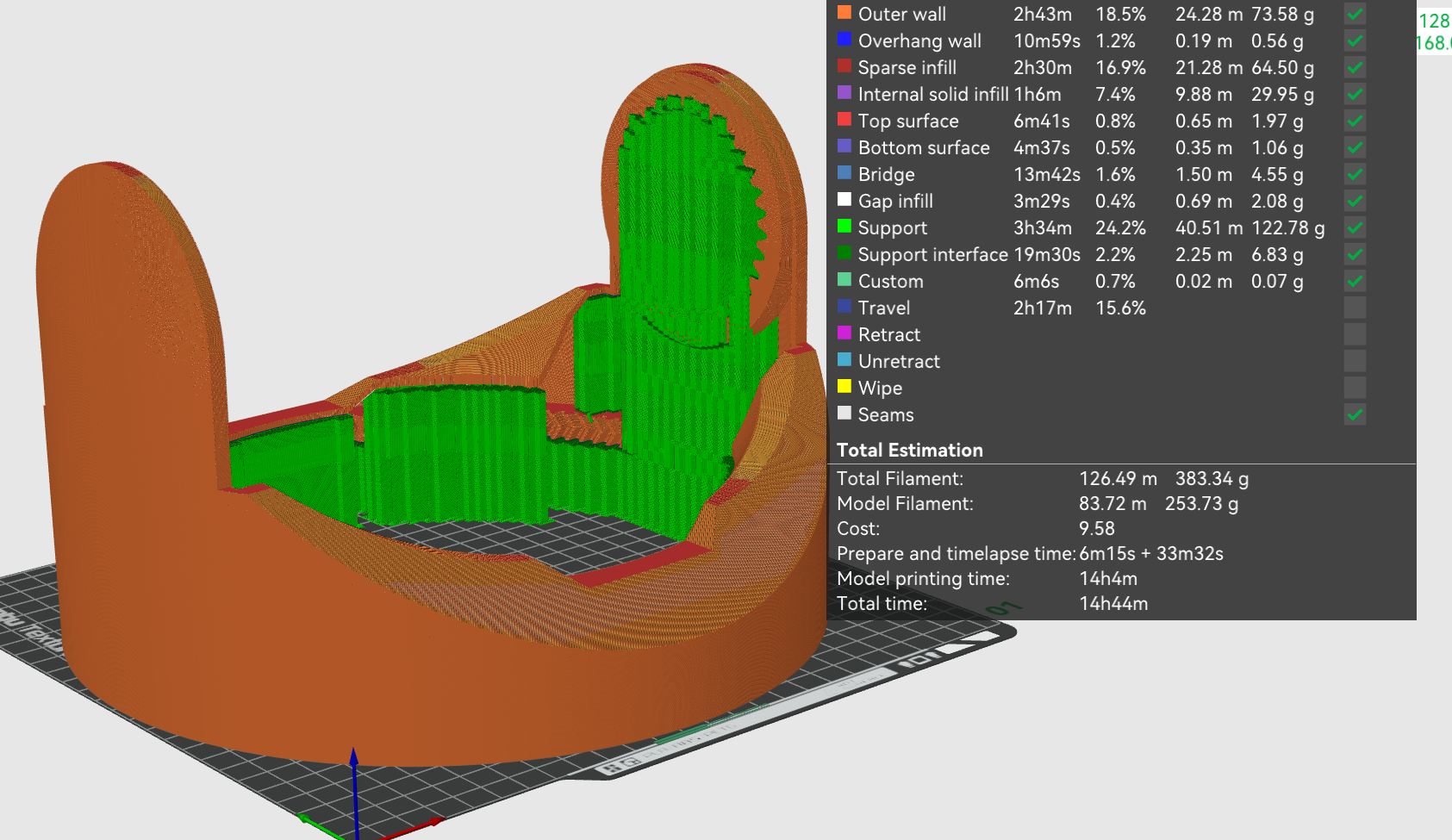
Option 2 (Using this one)
The second option for hiding the motor was inside the base itself, near the center and not on the fringes like the edge. This would use an internal gear (gears on the inside of the cylinder). Based off that, I redesigned parts of the middle base to allow for this smooth rotation. At the same time, I also added a place for a bearing and a gear to the arms of the body, and printed it to be a part of my final project. It is a LARGE print, taking up literally 95% of the Bambu Lab A1s build plate.
Battery
After printing out the middle, I started to figure out how I would hide (and charge) my battery. I decided on taking one of the legs, and found that putting the battery at an angle gave it just enough room to fit. I also inserted a slot for my charge module.
Smaller Board
As I described earlier, my stepper motor and board were a bit too big. To fix that, since I cannot redesign the stepper, I redesigned the board. Through some clever redesigns and accepting to use a V engraving bit instead of a 1/64inch, I was able to compact the design to no longer go over the lip of the stepper motor
Stepper Motor PCB for the camera
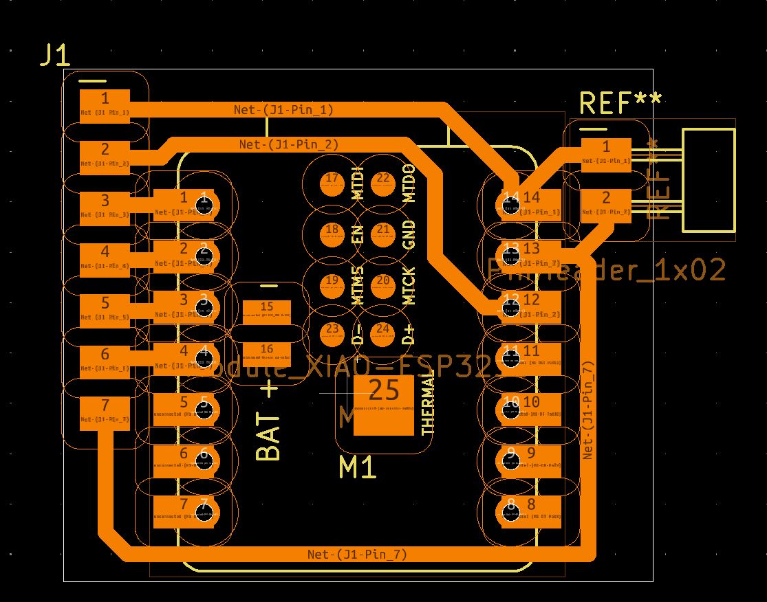
On the topic of PCB design, because im using a Xiao esp32-s3 sense, in order to keep the mess down, I designed a simple board with pins for the power into the Xiao and all of pins required for the stepper driver (7 total, 4 data 3 power). I also made the decision that in the interest of time I will probably not be able to add in the door opening-closing mechanism. I will do the 3d design with a way to do that, but I just don't think I could figure out the electronics for it in time.
I whipped up this quick design, making sure to use big traces and have a clearance of 1/28th inch. I found that I needed that, as I originally did it with 1/32th inch, but the bantam tools software said it wouldn't have any clearance.
These rules resulted in a board that could be milled in 2 minutes with only a 1/32 bit and no drill files
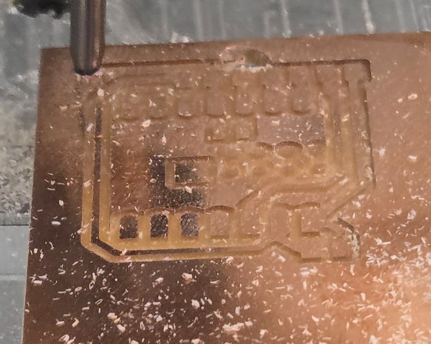
Milling Issue
The first time I went to mill the board, I used a board that was already seemingly taped down. However, once the milling started to do the outline
Successful mill
After retaping down the board, I remilled from the beginning and it worked perfectly
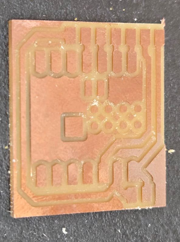
After soldering it, I had a pcb that would allow for easy routing of power to the board and all pins required for the stepper
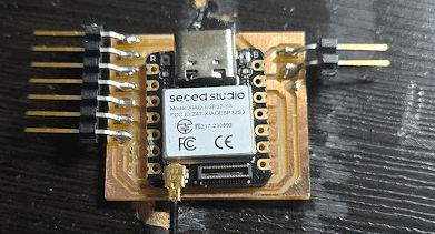
Mounting
While I realized after I soldered that I forgot mounting holes, Because I had the exact dimensions of the board I could make a press fit (with some more formal glue later) to hold it together.
This isn't where it is mounted, but it is how it will be mounted.
Reflection
This week was a long week of choosing the longest way to solve a problem. With the motor, I looked at internal, decided against it, then after seeing how obvious the gear would look, went back to internal and really easily did it. Of course I managed to work in PCB design, and even got mine reviewed by a great friend, fab academy graduate, and digikey sanctioned PCB design engineer Nicholas Niles, where he suggested the curved corners and some changes to the traces to improve things I cannot even begin to understand yet. This week was also the week that I started to physically make my final project, which resulted in over 50 continuous hours on my 3d printer. I was scared of not getting my final done going into this week, but in 4 days I got half my final made, so I am resolved to get it done in the first cycle.
Design Files
an STL of my 3d design, the current ESP-32-C3 PCB, and new xiao esp32-s3 camera PCB can be found here