Computer Controlled Machining
I have 2 desks that are arranged in an L shape. The problem with this is that the smaller of the two desks is about 3 inches taller than the bigger, which is really annoying to work with. also, because these are two different desks, some of the their legs go where my legs should go.
Design Consideration
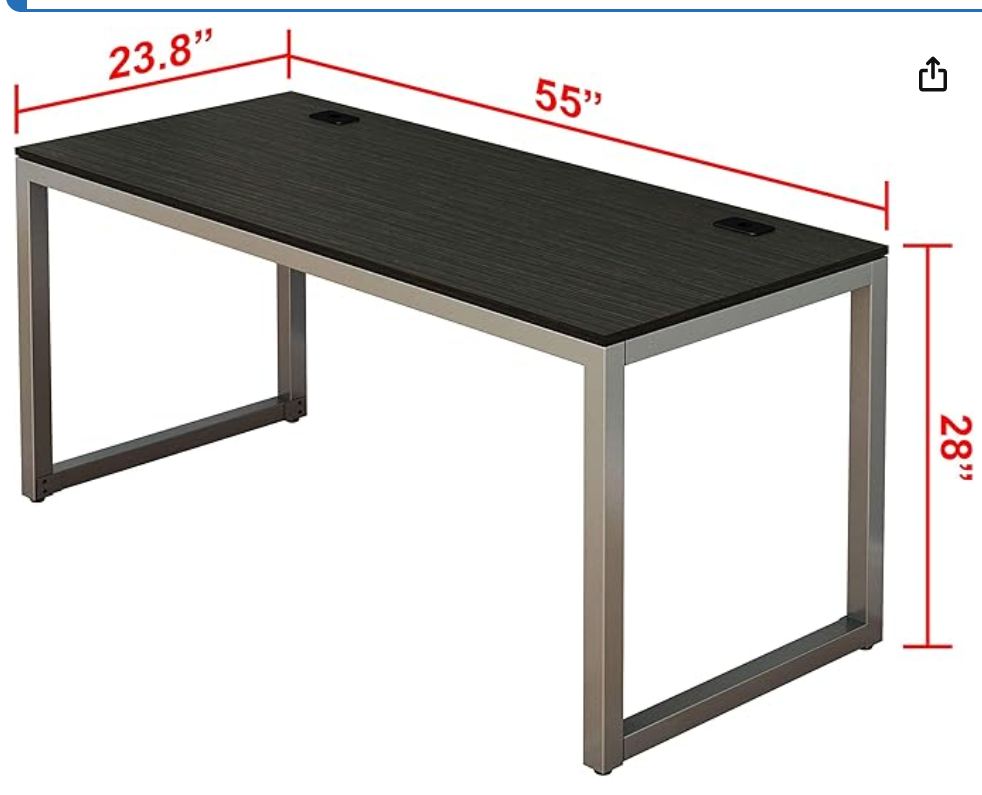
I want to make an extension to my desk, that is able to support my monitors, while being the same height(28 inches on the top). It also needs to allow my legs to move, which means part of its supports will probably be it leaning on the main desk, or some way of connecting them.
 https://www.amazon.com/dp/B07D5NWDB7?ref_=ppx_hzsearch_conn_dt_b_fed_asin_title_18&th=1
Design in fusion
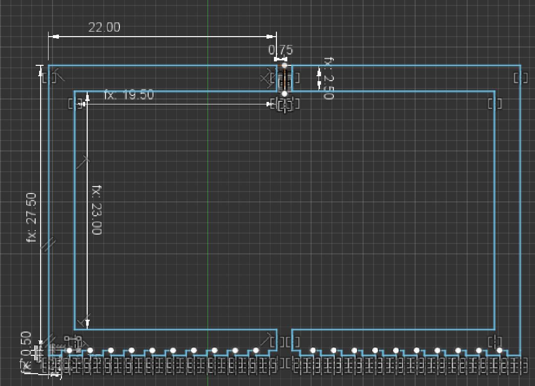
I standardized my design to all tabs being the material thickness (.75) by 2 inches, with material thickness being somewhere around 3/4 inches
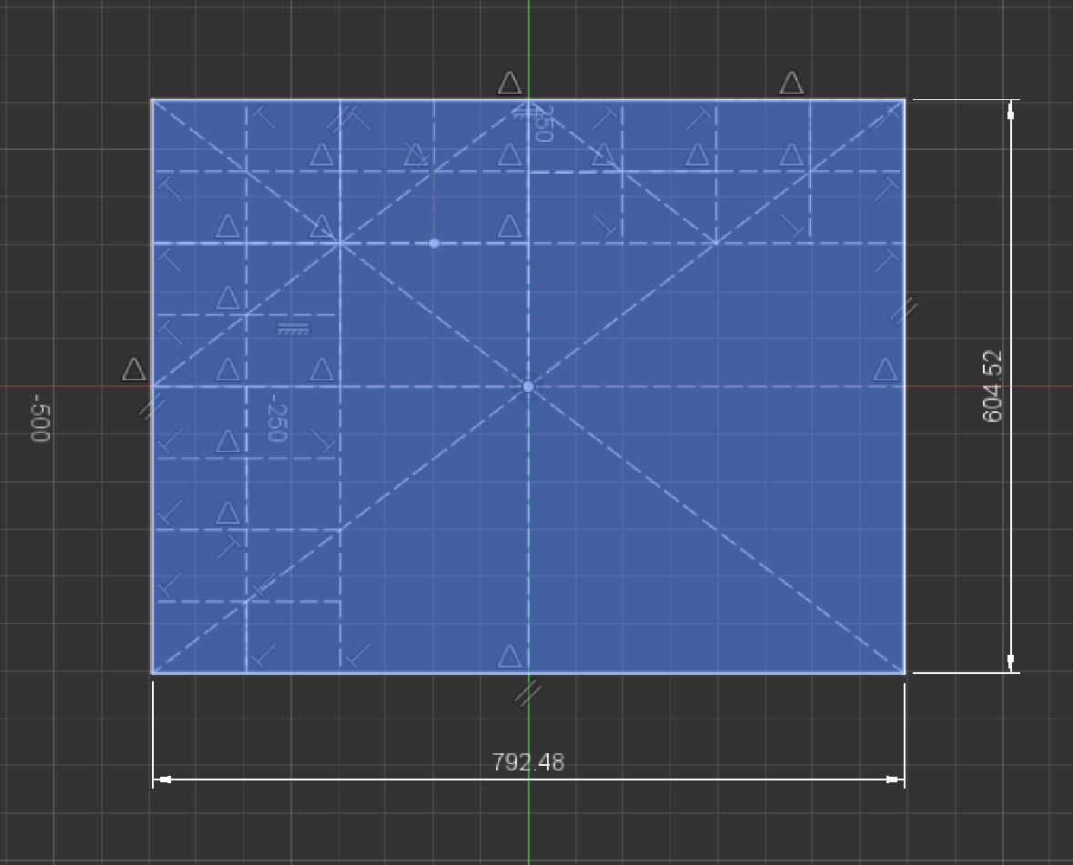 After doing all this gridding, I realized it wasn't square and had to fix that
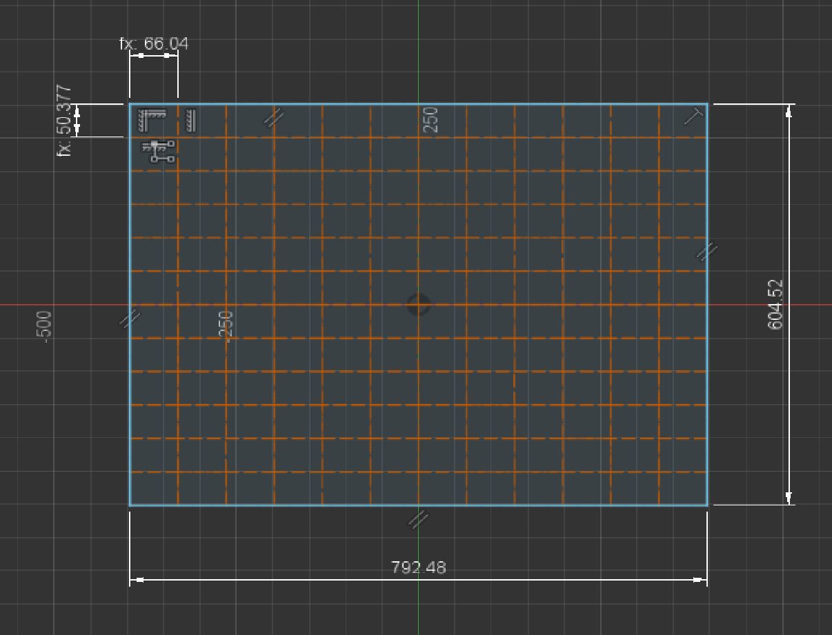
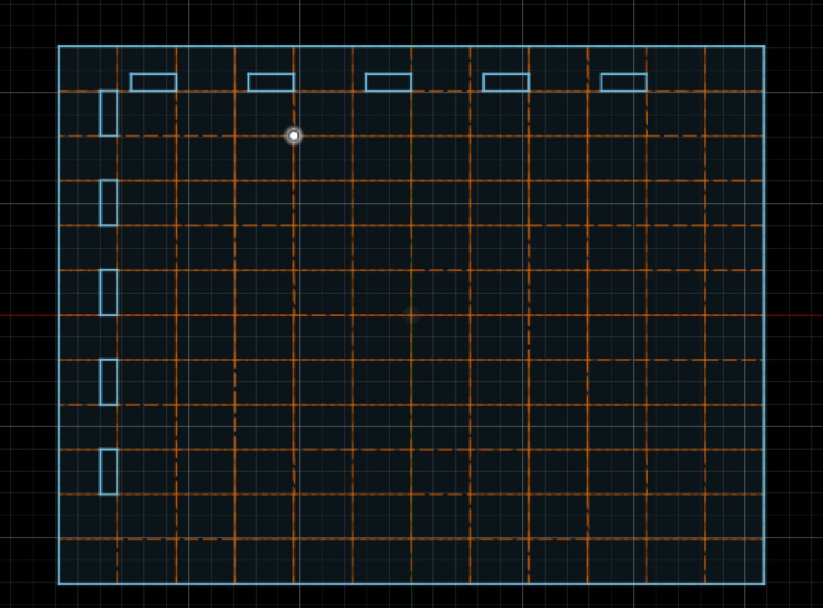
Units
 After designing this basic version, I realized something "What am I doing making a desk whose dimensions are inches, with wood whose dimensions are inches, with a design that reads in meters". I switched over to inches, which made my dimensions much more readable going forwards. Going off this, I set the default value in fusion to inches, since I really only use mm when it comes to PCB design, which I do in KICAD
After changing to inches, I went home from my lab and fully measured all of the space I had to work with. I found that I was making this too much like a square, when I need more of a wider rectangle so that my entire mouse pad can fit on it. I decided to start redesigning, while also trying to figure out other optimizations
Better Design in fusion
Theory
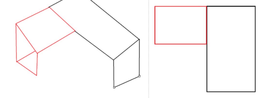
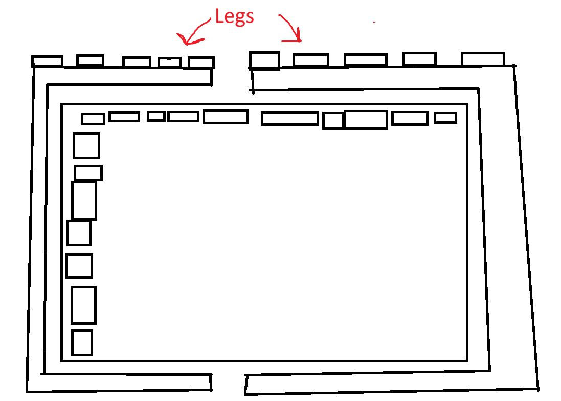
After starting the redesign, I had an idea to save space. seen in the really bad sketch below, I basically wanted to cut the legs around the top of the table, so that it used much less material vs cutting the legs besides the table top.
Legs
I started working on this first with the legs, planning on designing the desk to be as big as I could make it inside the legs. I decided on 11 tabs per leg, which looking back on it was way overkill, and lead to a lot of headache later. I made the leg in a U shape, planning on making one then mirroring to create the other. I also made sure to pay attention to using dimensions on important parts, like the height on the table, the amount of space between the top and bottom of the table leg, and the tab width and height.
Tabletop
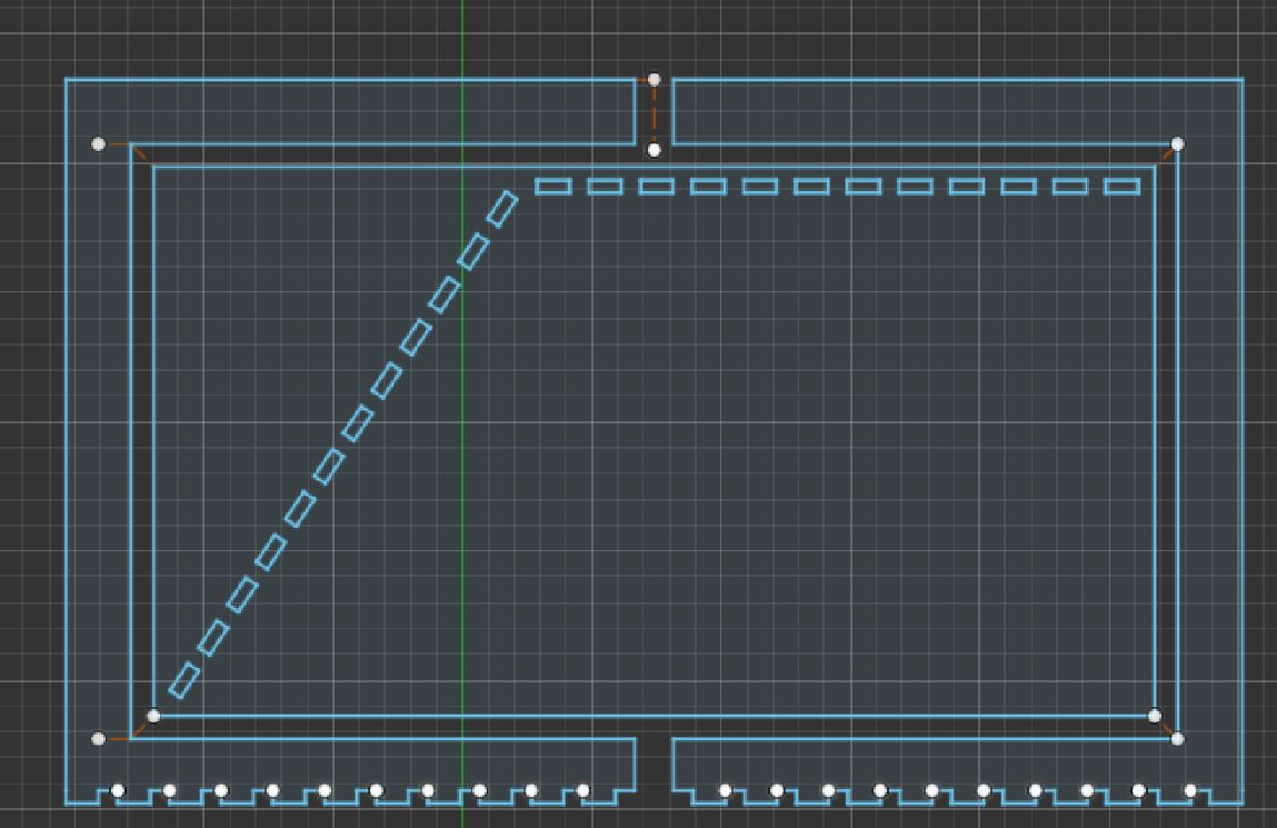
I made the table after making the legs, in order to get maximum desk space. I basically just made a rectangle inside the space, with around 1 inch spacing between the tabletop and legs. There was one issue I ran into when making this, which was that the legs were too big for the table, specifically the width of it. I fixed this by rotating the space for the legs, which I think also looks cooler than it did originally
Testing
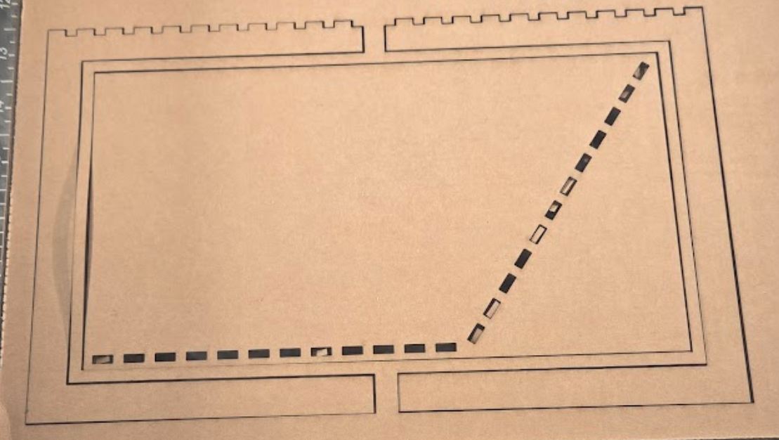
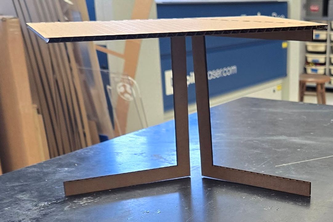
After finishing this design, everything looked good. I decided to do a cardboard test before on wood in order to realize my mistakes now. Because this was designed for .5 inch wood, and cardboard is (usally) .125 inches, I was able to simply scale down the entire design by .25x, which resulted in my design made for cardboard. After manually focusing to mitigate kerf, I cut on myy Fablabs laser cutter. After assembling it, I found that it wasn't that strong however, as it was attached by only 2 legs, and the supports for those 2 legs were right next to each other. I also found that while the legs had 11 tabs, I for some reason put 12 holes per leg onto the table,
Fixing
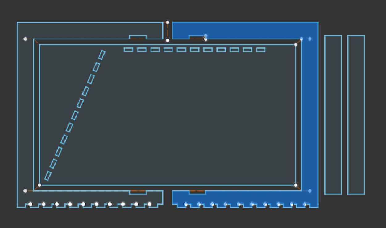
After that. I went back into fusion and tried to address the 2 issues. The easiest one was the tabs, which I just accidentally made when I told the pattern to make 11 copies of one tab, which resulted in 12 total.
For the second Issue, I had to figure out a way to give it more support. I didn't want another leg, as that would have nowhere to go with the other 2 already wrapped around the table. I decided on giving the legs more support with bars that I could add in. I added in 2 places for some wood planks to be added, then added in those 2 planks. I purposefully made them a harder fit than the other tabs, which would mean I definitely needed to sand them down but they would hopefully have more strength.
Second test
On the second test, I cut following the same procedure as the first, and it didn't fail again. This time, I had the right amount of tabs, and put in more thought about where I should put the legs. I decided on putting them farther away from where they both met, and then using the weaker planks in the middle.
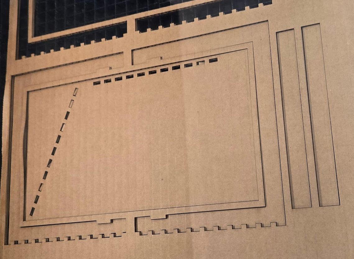
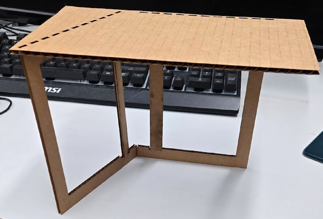 This time, everything worked much better, and it was able to stand on its own without me needing to keep it from falling over every couple seconds.
Aspire
After designing it in fusion, I had to put it into Aspire. Aspire is a CNC software developed by Vectric that is used for creating toolpaths and preparing designs for machining. It specializes in 2D and 3D carving, making it ideal for projects that require detailed engraving, routing, or cutting.
Setup
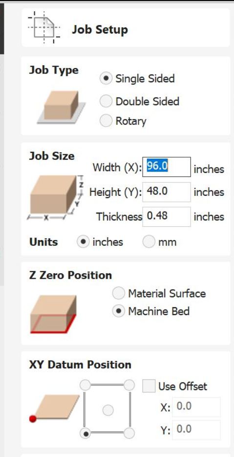 Before moving the dxf into aspire, I had to setup the page correctly.
Dimensions
The lab's shopbot is 48x96 inches
Thickness
While I originally intended for the design to be made out of 3/4 inch wood (usually around .7 inches), I changed to 1/2 inch wood. As with the 3/4 inch wood, its not actually 1/2, but usually between .46 and .49 inches. I found that on the computer that runs the shopbot, there was a design that was also cut into the wood I was using, and they used .48 inches there, so I used that for mine too. This was the biggest single mistake I've made of all my time in the lab, but ill have a big section about that later.
Importing
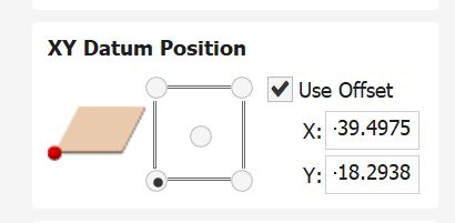
Importing from Fusion to Aspire is very similar to importing from Fusion to Coreldraw, which I talk about in my work for week 2. Essentially, I found a plugin called shaper origin, which allowed me to export sketch profiles into DXF's. I took the profiles from my fusion file, and imported them into aspire using File -> Import. I ran into an issue here, that I didn't notice in till right when I went to cut. The error it introduced here was that it made my offset go from 0,0 (good) to -39.4975, -18.2938. I don't know why it does this, but my instructor just asked me if I checked the offset before I cut and it was at those random numbers. so just if your checking this in the future, beware!!!!!!!!!!!
Construction Lines Problem
After importing into aspire, I ran into another problem. This time, it was that all of the construction lines I used (like the lines for mirrors) were imported as solid lines here, which messed up all the shapes. After removing making a backup of the fusion file, then removing the construction lines, I reimported into Aspire, rechanged the offset from random numbers, and it worked.
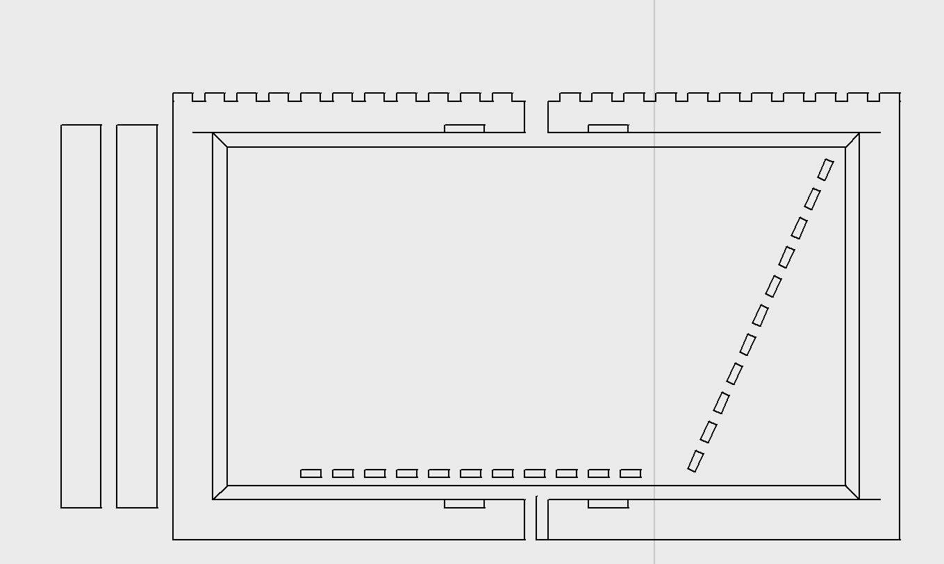
Dogboning
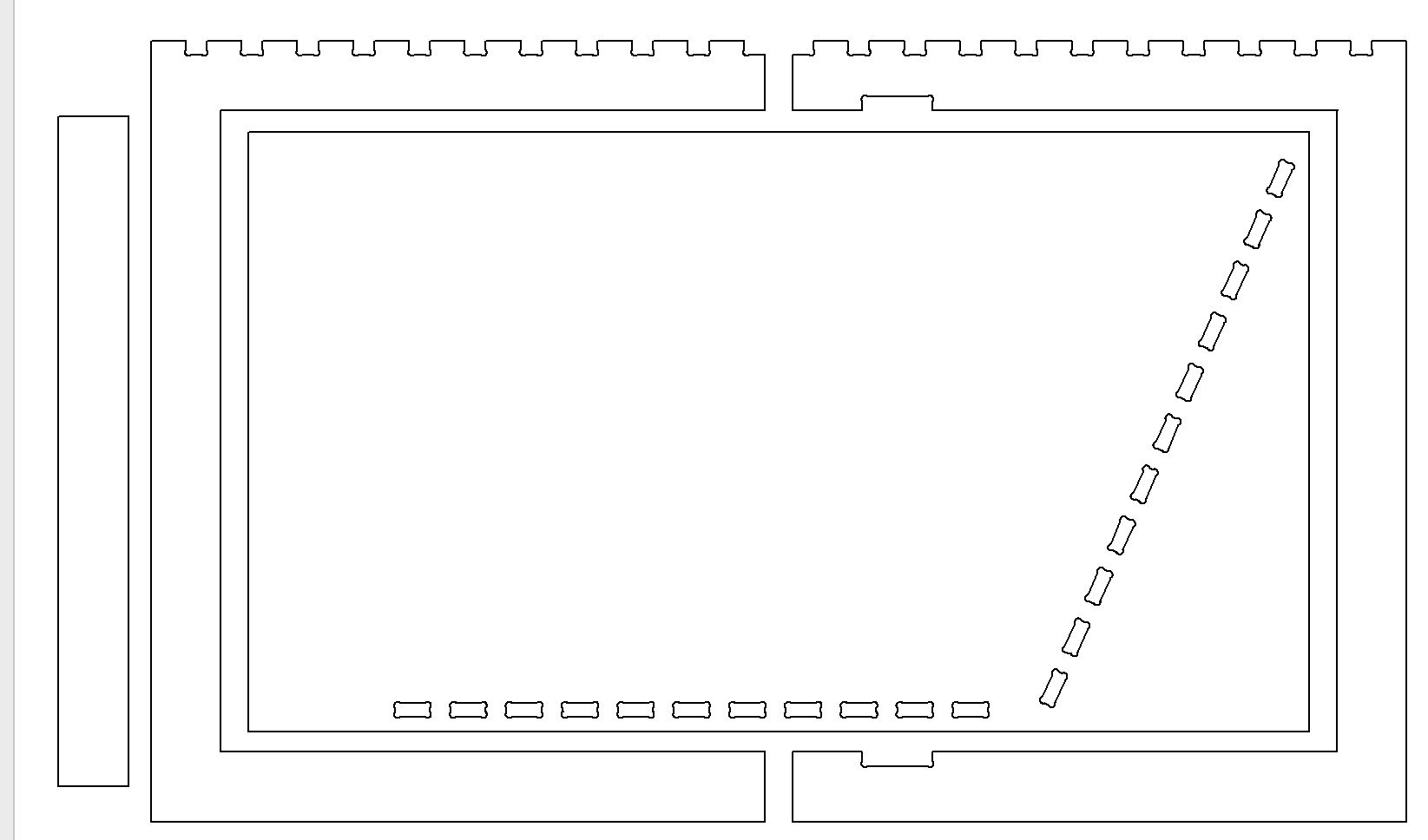
After getting my design into aspire, I had to add dogbone fillets to the corners of the joints
Whats a dogbone?
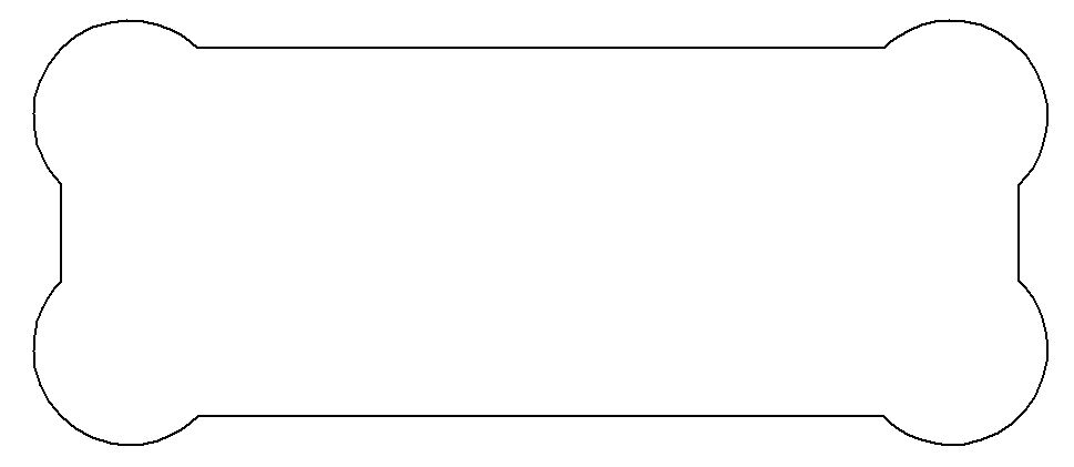
In CNC machining, a dogbone refers to a specific type of fillet added to the inside corners of joints or cutouts in a design. When cutting wood (or other materials) with a circular router bit, the bit’s round shape prevents it from creating perfectly sharp 90-degree inside corners. Instead, you end up with a rounded edge that can make parts fit poorly—especially in joinery where pieces need to slot together snugly, like in my project. To fix this, a dogbone fillet adds a small circular or semicircular extension at the corner, allowing the router bit to fully clear the material while still letting the mating piece fit properly.
Dogbone Issue
When I made my design, I originally intended for this to be cut on 3/4 inch wood. This changed when I went to dogbone, as in my lab it was highly suggested to use a 3/8th compression bit when cutting on 3/4 inch wood. The problem here is my tabs were so small a dogbone for a 3/8 inch compression bit wouldn't be able to fit on it, or more specifically Aspire doesn't support two overlapping dogbones.
Changing to 1/2 inch wood and fix
In looking into fixes for this, I realized that im cutting a desk that will hold a maximum of around 30 pounds, so what am I doing making this for a wood thicker than what I need. I made the decision to change my material thickness, which I luckily defined as a variable, from .7 to .48 inches. This messed up my design slightly, making some supports that were based on the material thickness a bit too thin, but after a bit of tweaks it worked fine. I then reimported into aspire for the third time, and ran into the exact same issue again, With the dogbones too big. I fixed this by just changing my drill bit size, from the 3/8th compression to the 1/4 straight. This solved my issue, as I was able to create a smaller dogbone (.125 radius instead of .187 radius)

Toolpath
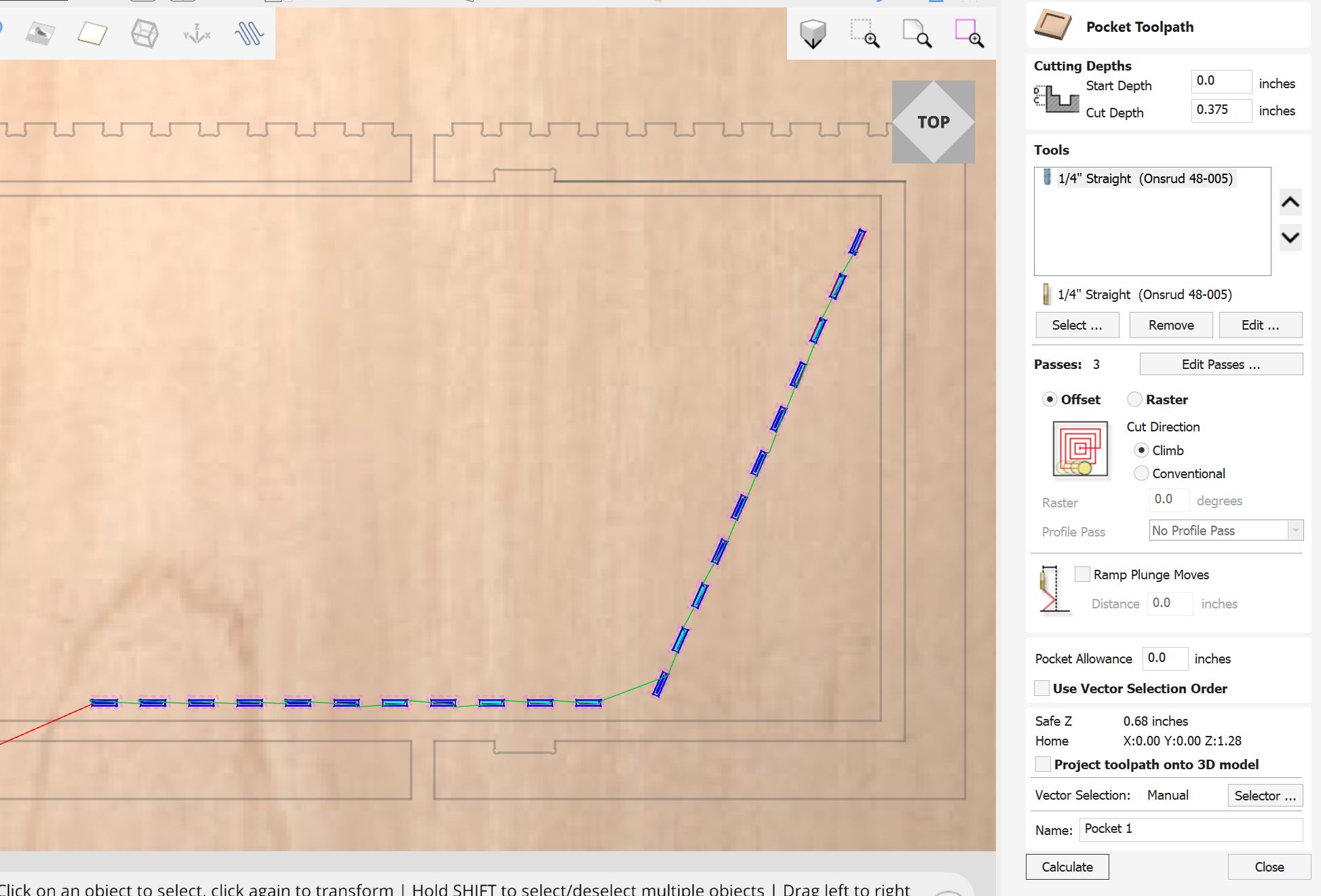
After getting the hopefully final design all set up in aspire, I started to figure out the toolpaths. I decided on two separate ones, a pocket for the tabs in the middle of the table, and a profile for everything else.
Interlocking Tabs
I did the pocket because I didn't want to have to make 4 tabs per tab I cut out, which would be 88 tabs that I would have to cut by hand if I used 4 tabs per cut. A pocket cut essentially removes all material in the area, vs a profile that removes an outline of the material.
Profile
After making the pocket, I made the profile cut. This cut cuts around the shapes, while doing its best to make them as similar to the design as possible. Like pocket cuts, It can fail at this for certain places, mostly corners, which is the reason that dogbone fillets are required. After finishing the profile, this is what my cuts looked like together on the aspire cut preview.
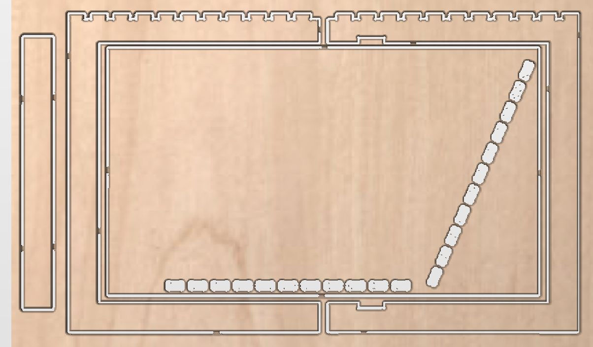
switching to profile
Later, while I was going to cut, my teacher (correctly) told me that because my tabs were so small, I didn't need tabs on them, and they didn't need to be pockets either. I copied the settings of the big profile, except for 2. I turned of tabs, as that was the entire reason I had switched to a pocket before, and I made the "Machine Vectors" setting to inside/left. This means that when it goes to cut, instead of an outline around the shape, it will cut inside the outline of the shape.
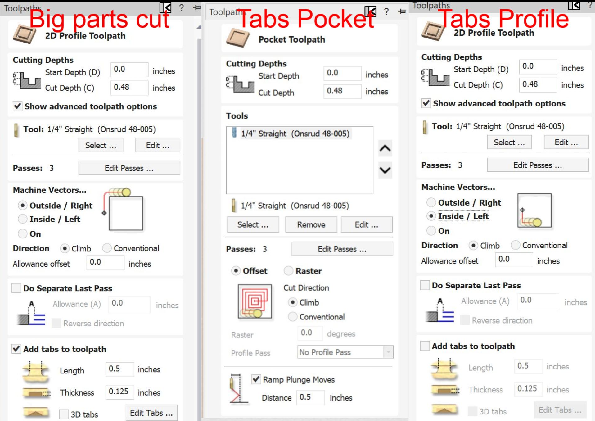
Shopbot Workflow
Cutting
Workflows
For all of my cutting, I followed these workflows that my school has curated for our shopbot.
Final Issues Check
Before I went to cut, I did one final issue check. In this check, I found the issue of the offset, which I talked about here in the importing section
Start Of Day Routine
this workflow
Unluckily for me, the shopbot had not been used before me, and therefore I had to run the start of day routine. The start of day ruotine for my lab is very simple, you just turn on an air compressor, wait for it to fill, turn on the shopbot, wait for it to home, and turn on the spindle, then wait for it to warm up. It took around 25 minutes, mostly because there was a open valve right next to the compressor that was greatly slowing down the pressure buildup, and I was too scared to close it since it wasn't in the workflow. Turns out whoever made it just forgot to add that to the workflow, but after asking a teacher they said to close it and it just worked.
Air Cut
this workflow
The Air cut was very simple, I moved the spindle to be about a inch and a half above the material, using zero z to have the machine think that even when in reality it was floating a couple inches above the material, and then started the cut. The shopbot spun up, and started cutting in and out of the air above where I wanted it. This is run mainly to test if your positioning is right, but also checks if you have some errant toolpath that would start trying to rip the bit apart in the wood before you go to cut.
Real Cut
this workflow
The cut was very similar to the aircut. I rehomed from the aircut, then started the cut.
Issue
About 5 minutes into the 15 minute cut, The cable connecting the shopbot to the computer was stepped on. This immediately caused the cut to stop, and it could not be resumed. This was a pretty easy fix however, as thanks to the shopbots repeatability, I just ran the cut again and it cut in air for the first 5 minutes.
Post Cut
Really Big Issue
After that, It got back to cutting again and worked fine. However, after the cut ended, I noticed that, due to warping in the board, it hadnt cut through all the way in the middle. This is very very bad, as because it cut through fine on the parts closer to the edge of the wood, that meant I couldnt just run the cut again while cutting deeper, or I would start cutting grooves in the spoil board.
Solution
The fix we came up with was to just manually cut the last bit out. The good thing was that everywhere it didnt fully cut through also didnt matter alot for how good it looked, because it was either part of the table legs or the underside of the desk. This meant that we didn't have to be that gentle with it. My teacher found a random crowbar that our lab just has, and we were able to cut and yank the board out. Below is a picture of what some of the tabs looked like
Filing
After getting the wood off of the shopbot, I still had holes that hadn't fully cut through. It was so thin however, that I just took a metal filing tool and pushed through easily, but it did mark up the wood a bit.
Too Tight
I then went to try to fit all the stuff together, but of course it was too tight. If I had to guess it, I made my tabs for .48 wood while the wood was .50-.51 in reality. This meant that every tab had to be slightly expanded in order to establish a good fit.
A Hour of Filing
In order to widen the holes, I had to file them. I made the really dumb call to use the worst possible filer that are lab had, that was more like really fine grit sandpaper, and therefore took a really long time to actually get material off. Using it, I spent about a minute per side of the tab just filing it down. My process was to sand, check, sand, check, untill when checking it fit together. It was kind of worth it however, as it gave an incredibly tight fit that im unable to pull apart.
Combining With the Old Desk
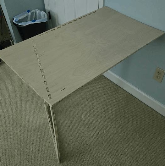
after getting the desk to stand on its own, I had to add it to the main desk. For this I designed really tight 3d prints that fit both the old one (.46 inches on the edge) and the new desk (.52 inches on the edge). I made a simple sketch in fusion, and then printed it. It miraculously fit really well first try, but I did print multiple to give it more than just one point of contact between the two desks. This are essentially acting as the third leg on the desk, supporting it on the right side while I have the legs support the back and the left
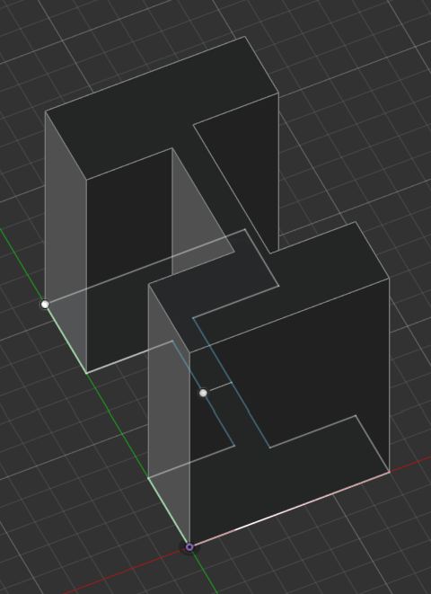
Hero Shot
Group Work
A link to the total group work can be found here
Safety Training
Before we even touched the shopbot, we watched the lecture for this week and received a detailed safety training from our local instructor, David Taylor. He went over all safety involved with operating our machine. The main resources he used were from this google site and this workflow. When going to mill, we would follow the workflow exactly, as it described everything required for setting up the machine and software, aswel as useful troubleshooting tips. Our shopbot also has useful add-ons. The two ones that keep us most safe is colored grip tape on the floor to tell us where its actually safe to stand, and a spindle power interlock that allows us to disconnect the spindle (bit rotating motor) from any way that it could be powered
Materials
We have 2 different "classes" of milling machines at our lab, we have the big ones with the small shopbot (2'x4') and the large shopbot(4'x8') and the smaller bantam tools milling machines.
Materials that we cut on our larger machines
-Wood (oak, walnut)
-Plywood
-Softwoods (pine, cedar)
-Foams
The shopbot can also cut alot more than this, but we just don't use those materials in our lab.
-MDF
-Acrylic
-Plastics
-Metals
Of course, every different material requires different feeds, speeds, bits. Some even require dust collection due to the harmful nature of their chips to humans or the cut.
Reflection
Designing
Designing is the funnest thing for me, I love to design it, but making it was not fun (as seen below). I started out designing just at random, then I decided on it being a corner desk that sort of requires learning onto the main desk, and then I started figuring out how to make that while using the least amount of material possible. All of this was a fun challenge, and incorporating a variable for material thickness, tab width, and table height saved me from a manual redesign when I made the choice to cut at .48 inches material thickness instead of .5, which kind of sabotaged me. Also I think I should of used what I learned the Computer Controlled Cutting week, and chamfered the edges or used a better joint than what I used.

Cutting
The shopbot is real scary. It is the only machine in the lab that I can describe as able to kill you without you putting your hand into a sawblade, which I absolutely hate. I did however gain a new appreciation for the machine, and mainly the really good workflows my lab has for them. Last time I milled something on the shopbot, it was a school project on a scrap piece of wood that my teacher forgot to throw out. I managed to make it work then, and it wasn't that painful, and it wasn't hard here either. The only hard portion of it was that start of day routine, since the workflow wasn't updated and didn't include a step. When it actually got cutting, The previous brads in the material also caused it to be .005 inches taller on the left side of my cut vs the right, which lead to half my tabs not cutting through. The workflows and Dr. Gershenfield's lecture were made for a shopbot in a perfect world. The problem with this is that my schools shopbot is also run by middle schoolers, so this is definitely not a perfect world. Its annoying, but for my second ever shopbot cut it definitely taught me a lot about what to be aware of in this lab.
Post Processing
Most boring hour of my life. Because of the issue mentioned above, I had to go through and manually cut out about 10 of the tabs, and then file down all of the tabs. I got it done, and the final fit was really tight, but it was not worth the effort, and I pray that I never have to do this again. But I wanted a desk, and a desk has to hold things, so a really tight fit is for the best here.
Design Files
All design files for the desk, aswell as the 3d printed connector, can be found here
