Molding and Casting
Design
My design is split between before making the small mold for a test, and after it
Before Small Mold
This is when I was just doing it all on the computer. It took a bit to design, since I couldn't figure out the best way to get started. I started with designing the window, which was made using a sketch revolved 70 degrees

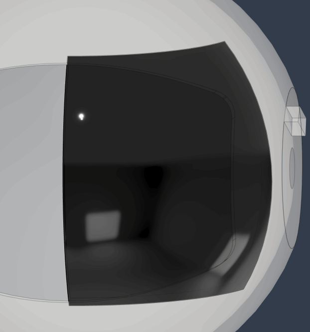
After designing the window, I started on the mold. after alot of testing and failures, I found that a bunch of lofts, or basically shapes formed by connecting to faces were the best. Using multiple lofts, I was able to loft the back side and the windows edges to one plane, and the front side to another
Draft Angles
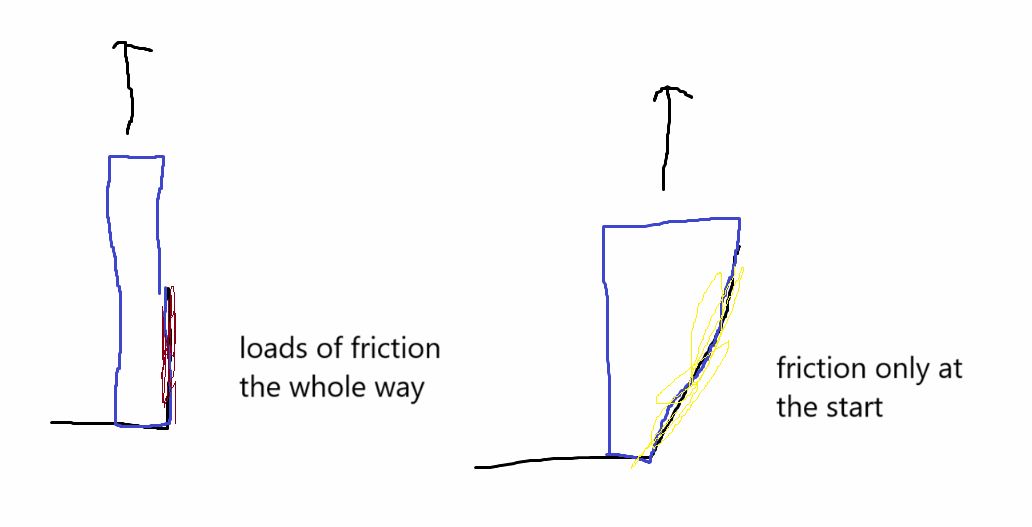
The way the lofts worked also automatically added in draft angles to the design. Draft angles are places where instead of it being perpendicular to your mold, you add a very slight lean so that when you are pulling the mold vertically out, it doesn't constantly have the friction it would have otherwise
After Small Mold
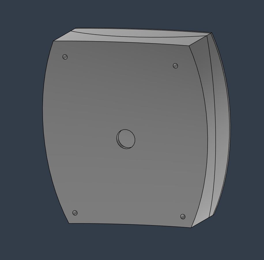
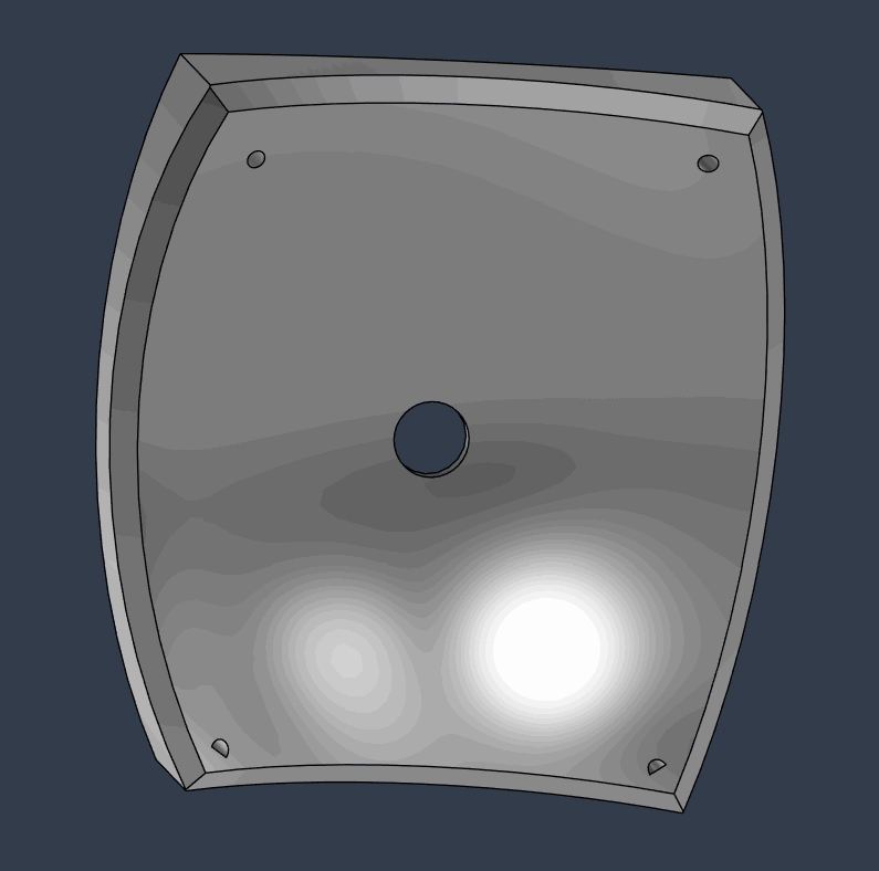
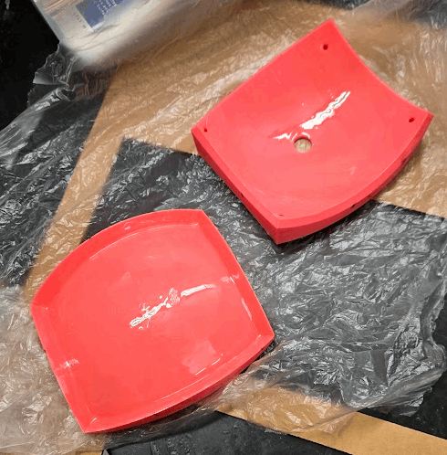
after I saw the results of the small mold, I knew that I needed to add something to make it easier to split the two pieces apart. Also I realized that I forgot to add a place to actually pour the material, as well as vents for all of the gas that would come from the slightly exothermic chosen material of 2 part epoxy. The main redesigns were just adding a bunch of holes everywhere, where I decided on a hole in each corner, as well as a main pour hole right at the apex
Final

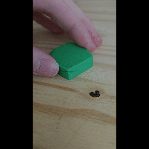
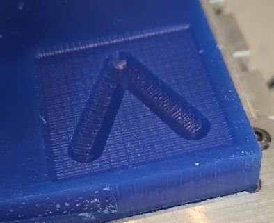
Small Version
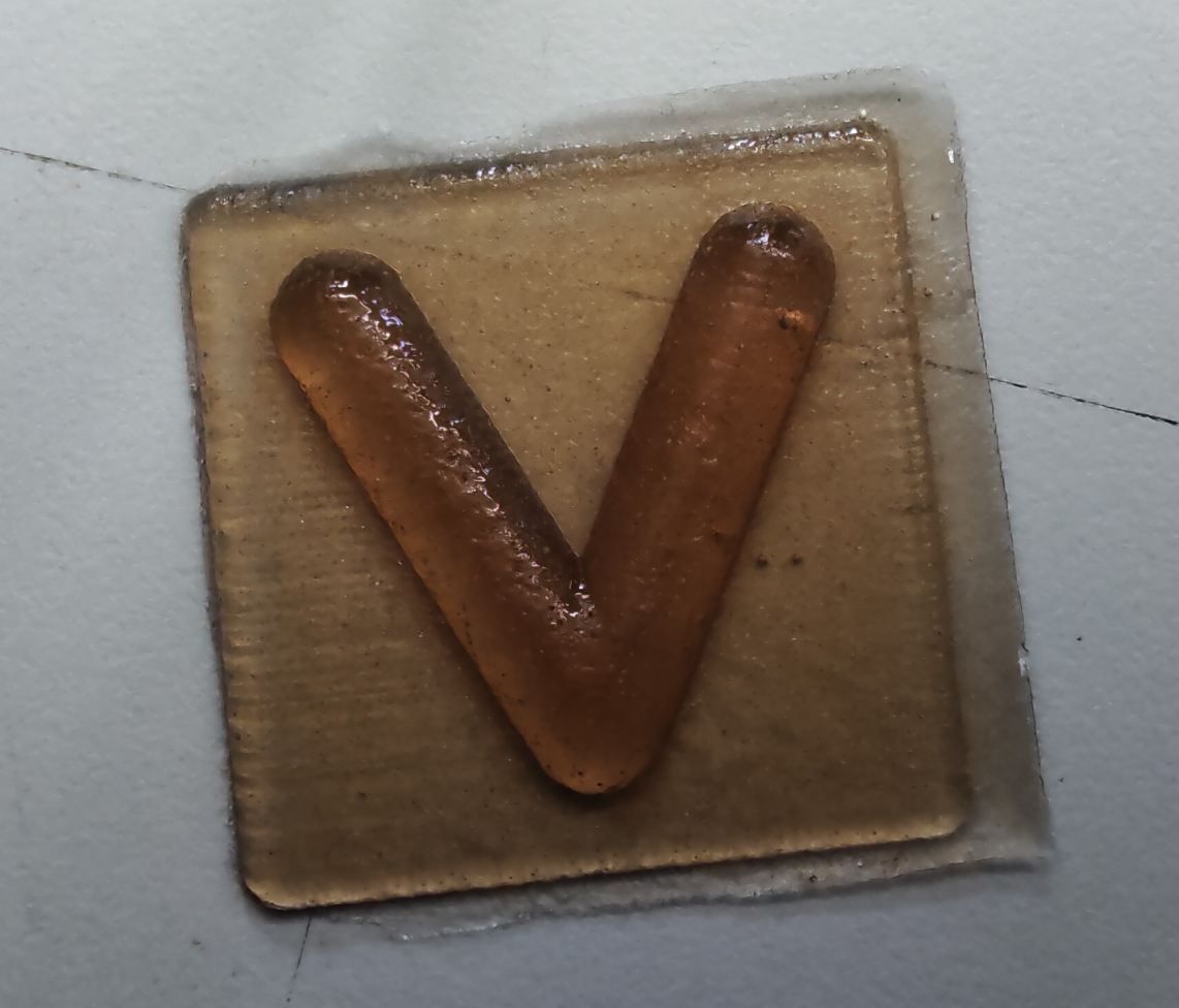
The small version, about 1/4 the size of the actual mold, was made early on in order to ~~get this week done on time~~ test the viability of my larger mold.
Making: Milling vs 3D printing
For this, and my project in general, I decided on 3d printing the molds. This was mainly due to the time, as even though milling is quicker, taking in account the actual work I would have to do to set it up makes it much more labor intensive then 3d printing. The downside of 3d printing is that I have to smooth out the surface after, which I used for the big one but not the small one. I (luckily) made the correct guess that this is just so small that such detail will be really hard to transfer, and because I printed it at 0.08mm layer height, it came out good enough to not show any of those layers.
Material
For the smaller mold, since it was using less than 5 grams of material, I just took what my classmate, cooper used for his. He used a silicone material, which was good as I was making a rigid mold and it is nearly impossible to remove a rigid cast from a rigid mold.
Making
Since the mold was so small, I basically just put some of the mold material (which probably was expired it looked pretty chunky), and just smashed the plates together until it stopped squeezing out of the sides, as seen in the gif
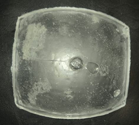
Results
After giving it a day to set, I now had to peel the two parts apart. Using the small leverage I could get on the side of it, I eventually managed to pop the top off
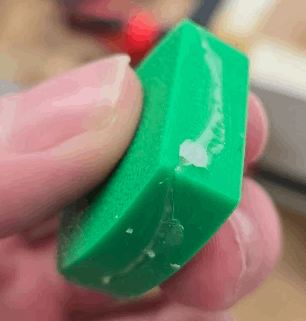
This was exactly what I wanted, besides that it was flexible and way smaller than the actual thing. As a proof of concept, it affirmed that I needed to use XTC-3D for the big one, as well as reminded me that I need vents and a pour hole for one that I can't just smash together
Big Version
Size
For the bigger version, I finally decided on the size of my final project. I decided to make the window just big enough to fit into the build plate of my a1 mini, and then slightly tweaked it so that another part was the same size as the buildplate of the a1 regular. This ended up being a the mold having a size of just above 170mm on its longest axis.
Making
just like the small version, this was 3d printed. The total time to print it out ended up being 3 hours per part, and just over 6 hours total. After getting my molds, I again used XTC-3D in order to smooth them out
After 2 hours, and a careful application of heat with the heat gun, the XTC was fully cured. I then started to mix my material
Material
Here, because of the requirements of this being a clear window, I needed to use something clear. Following a teacher's suggestion and past experience, I decided to use 2 part resin epoxy for this.
Datasheet
Before actually using the material, I had to check the datasheet. The datasheet pointed out a few key points for the process of using it. The datasheet can be found under the specifications tab on the specific epoxies page
The main points I applied when working with it was - 1.2A:1B weight ratio. Since I didn't have any clean volume measuring cups, I instead used a scale and the weight ratio in order to get the proper ratios. - 40 minute Working Time. working time just stands for pot time, but its basically how long can you actually effectively work with it before it starts to solidify and just get impossible to work with. - 5-7 Days Full Cure Time. Im almost certain that they are vastly overestimating this, as when I worked with it in the past, it was cured in anywhere from 24-30 hours. Besides for these key points, I also paid attention to it's shelf life
Doing it
Once I had all the 3d prints, actually mixing and pouring was just a simple set of steps to follow.
Preparing Epoxy
Using the weight ratio, My final weights ended up being 160.4 grams of part B, and 196.6 grams of part A. This ended up being 1.226g of part A to 1 gram of part B, which was good enough. I then thoroughly mixed, being careful that I now had 40 minutes to finish my pour upon starting mixing.
Preparing Mold
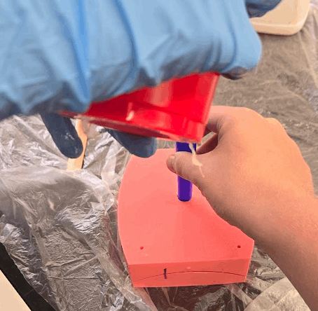
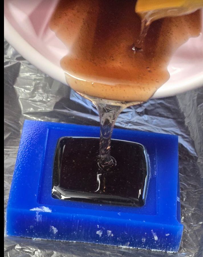
I started with a coat of ease release spray, which I applied a thin layer of over my now smooth 3d print. This would allow for it to be, easily released. After giving that a coupe minutes to cure (although it was basically instant, better safe than sorry), I put my mold together and started to pour. The mold was designed with a central pouring spot on the top of it, so I poured there and let the epoxy flow down the mold.
Pouring
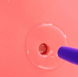
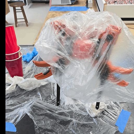
The actual pouring was pretty easy. After finding a funnel that fit almost perfectly into the "pour hole", I just started pouring. Eventually, it started to overflow, and I had to be careful to pour slower from then on. After getting the pour rate down, I eventually had it no longer accept anymore mold, so I smoothed out the top as best I could, although some epoxy got basically on all edges of the mold in that process. I then used duct tape as a buffer layer, and put clamps over that to hold it very tight. I also covered it in plastic in order to prevent other people ruining anything by touching it and moving it to a secluded corner of our lab.
Result
Heres where everything went downhill
it was Stuck
After 2 days, the exposed resin had been cured for a day, so I assumed it safe to start opening the mold. The problem was that although I had used XTC-3D, the easy release spray, and the mold had built in draft angles since the sides of the window were slightly curved, it still refused to come apart. After an hour of pushing and pulling, I had a really simple idea. Drop heavy weight on it... Somehow, using a 45 pound dumbbell on it instantly opened the mold, and caused me a big realization about a potential wildcard week (in reflection).
Bad News
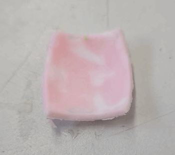
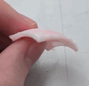
My cast was described by my brother, a 2021 fab academy graduate, as the "worst cast hes ever seen". In the mold there were 1. Bubbles everywhere 2. too much material where the pour hole was 3. opaque 4. a bit bumpy
While this week is over and time has started to close in, I still want to do a really big reflection on all of these issues + what I should of done + the inspiration I got from breaking open the mold
Individual work for the group
As part of my group work, I wrote about the process I used that worked, here im writing about the process I used that didn't work but was a good introduction. In this process, I used Mods to compile a simple stl for milling, and then attempted (but failed) to mill it on my new milling machine, but succeeded first try using the othermill. I only documented the successful mold for the group work, but getting my milling machine set up was good experience so im including all of that here.
Milling Machine
On my birthday, my awesome parents asked my fab academy graduate brother on what they should get me. He suggested a milling machine since I like making so much, so I had a new one right as moulding and casting started. The specific machine I have is found here, a variant of the 3018 frame just like how there are variants of ender 3s everywhere.
Connecting it to my computer
After following the tutorial booklet to set it up, I connected to my computer. The software it included was candle, but I'm currently looking for other software (Universal Gcode Sender looks good right now).
How should I turn stuff into Gcode?
This was a big question for me as I got it, as I had no clue how to use milling machines past the streamlined flow of the othermills. Heres where I remembered about Mods CE. It is basically a browser based tool for preparing a file for milling and laser cutting. Through alot of guess and checking, and this fab academy student's page who described how to use it with another milling machine, I eventually figured out my workflow. Im going to end here, as everything that actually worked can be found on my group page
Second Datasheet
For this mold, Me and [cooper] poured ours together with the same material, both for the group work. The material was PMC-746 clear amber. This is a material made for molds like this, and it excels at it. It features high safety, basically requiring you to eat it to get hurt by it, easy mix ratios, fast pot life (15 minutes), 16 hour cure time, and very flowy viscosity (1200cps)
Pouring
After reading through the datasheet, We mixed 24 grams total of it. Because both of our molds were small, even this was a bit of overkill, but made mixing the material together quicker.
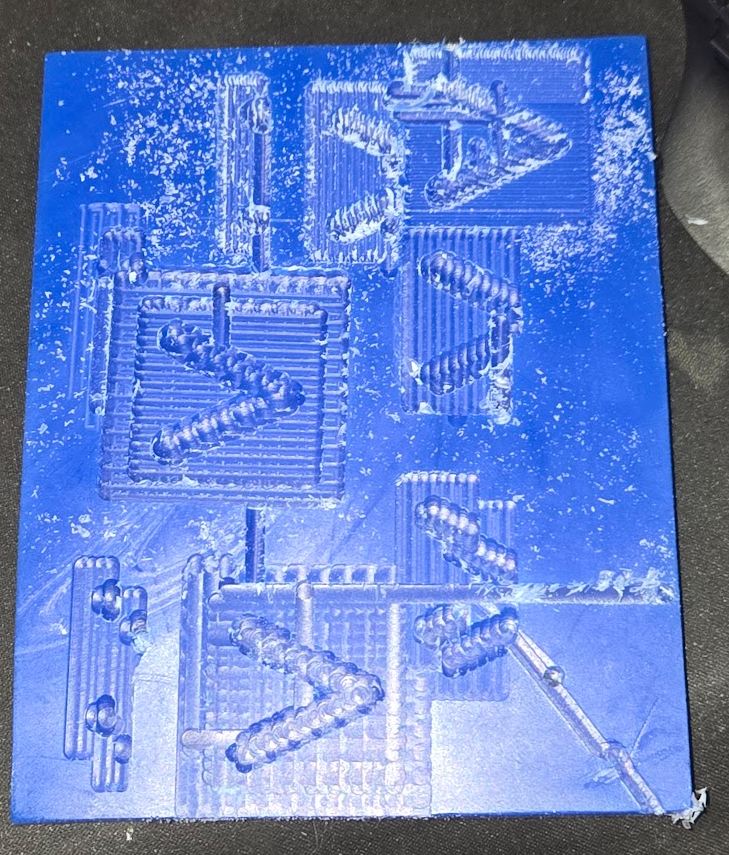
Hero Shots
the top right doesn't seem impressive, but it was my first ever thing on the milling machine.
for the bottom left, I'm not proud of how it looks, but it was the only possible outcomes as I combined a really hard material to work with and inexperience.
Reflection
This week, like my input week, had me do something really bad for the individual, but then for the group work do something better
Window Mold
What I should of done before printing the mold
After making this, I did a deep research with googles gemini on the subject of break away molds. It pointed me to a lot of different things, but formlabs eggshell ("Eggshell Molding" on the left) looked like something I definitely should of done. Essentially, it prints a really thin shell of what you want, with a small hole on the top. You then pour in the material, and because this was made for SLA molds, you can simply chip away the shell around it to extract a smooth cast.
A theory on how I could of done that
I think that, modifying that to use a FFF 3D printer, could be feasible. This is where the big idea I had was, as if I designed the mold in such a way that it had a weak spot, then I could easily break it right there to get to the contents within, without having to go through what I when I actually made it. The drawbacks of this is that I see it as print in place, and therefore could not apply easy release or xtc to smooth it out, but Im thinking that it could either be adapted to be made in 2 parts, or with enough post processing effort could be sanded/processed in a way I don't even know yet in order to get a smooth finish.
What I should of done while pouring
Heres where I introduced the air bubbles, the overflow, and a lumpy surface. The bubbles were introduced by my pouring, in which I poured way too fast. I also poured too much, and I definitely should of measled the volume of the window in fusion 360 (which Ive done before for other things) then used some math to figure out how much epoxy I had to mix, and mix a bit over that just to be safe. As for the lumpy surface, I should of been much more careful when applying XTC-3D, ensuring that I did an even coat everywhere.
What I should of done while extracting the mold
I should of simply been more patient. Using a hot air gun on low temperature and a pry bar did get me some progress, but I got to impatient and went the smash route. That route did inspire me on how I could make molds in the future, and its a really interesting route I barely see any talk on.
Milling Machine troubles
As of writing this, the only thing I can think of for the reason as to my machine not working is the cable sometimes looses connection. This seems very likely as its crashes aren't power outages, but rather it just carries out a g code command a bit too hard, for example going 4x the distance it should of gone. Although I couldn't get it working, each time I would figure out another problem with it and fix it. While I did run out of material, I have an idea im pretty confident would be its fix, as it basically seems to drop the connection from the computer every so often, so new cable + software might be good enough.
Group work
Setting up my milling machine was really fun. I think my brother bought it mainly for PCB making, as that is what I really enjoy doing, but its a happy coincidence that getting it aligned with milling week. It got pretty annoying using it and failing repeatedly, but everything a learning experience and im really excited to learn more about using it.
Learning mods was actually really useful though, as I used it on my personal machine, then did a bit of testing and found that weird gcode quirk, fixed it, and used it on the othermills at the lab, then taught one of my fabmates on how to also use it for their group work.
Group Work
A link to my groupwork, once it is done, can be found here. I wrote about the process that worked for milling a mold, then listed its advantages.
Milling - Noah
Part of the group work was to compare different methods of making molds. Our lab has 2 methods, 3d printing and milling, and everybody choose to 3d print their individual mold. For the group work, I milled out my own mold out of machining wax, which has a good guide for the othermill here.
File Preparation
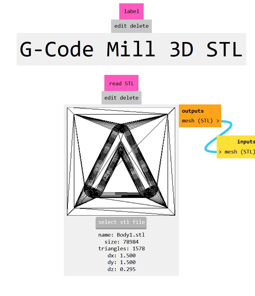
For some reason, importing stl's onto bantam tools software didn't work, so I had to find a different method. For this, I remembered what Dr. Gershenfeld had said a long time ago about Mods. Learning mods took way too long, as searching for mods, or even mods community edition usually just gave video game mods. I eventually found this fab academy page for electronics production that described how to use mods to make PCB's with a specific milling machine my lab doesn't use. Through trial and error, I eventually found that on the mods page
right click -> programs -> open program -> G-code -> mill 3d stl.
After loading that program, I loaded my stl file. Be careful when exporting that stl from whatever software you use that it is a Binary STL using inches as units. If not, it will make 1mm equal to an inch and the website will crash trying to compile such a large model. I took that STL and put it into the
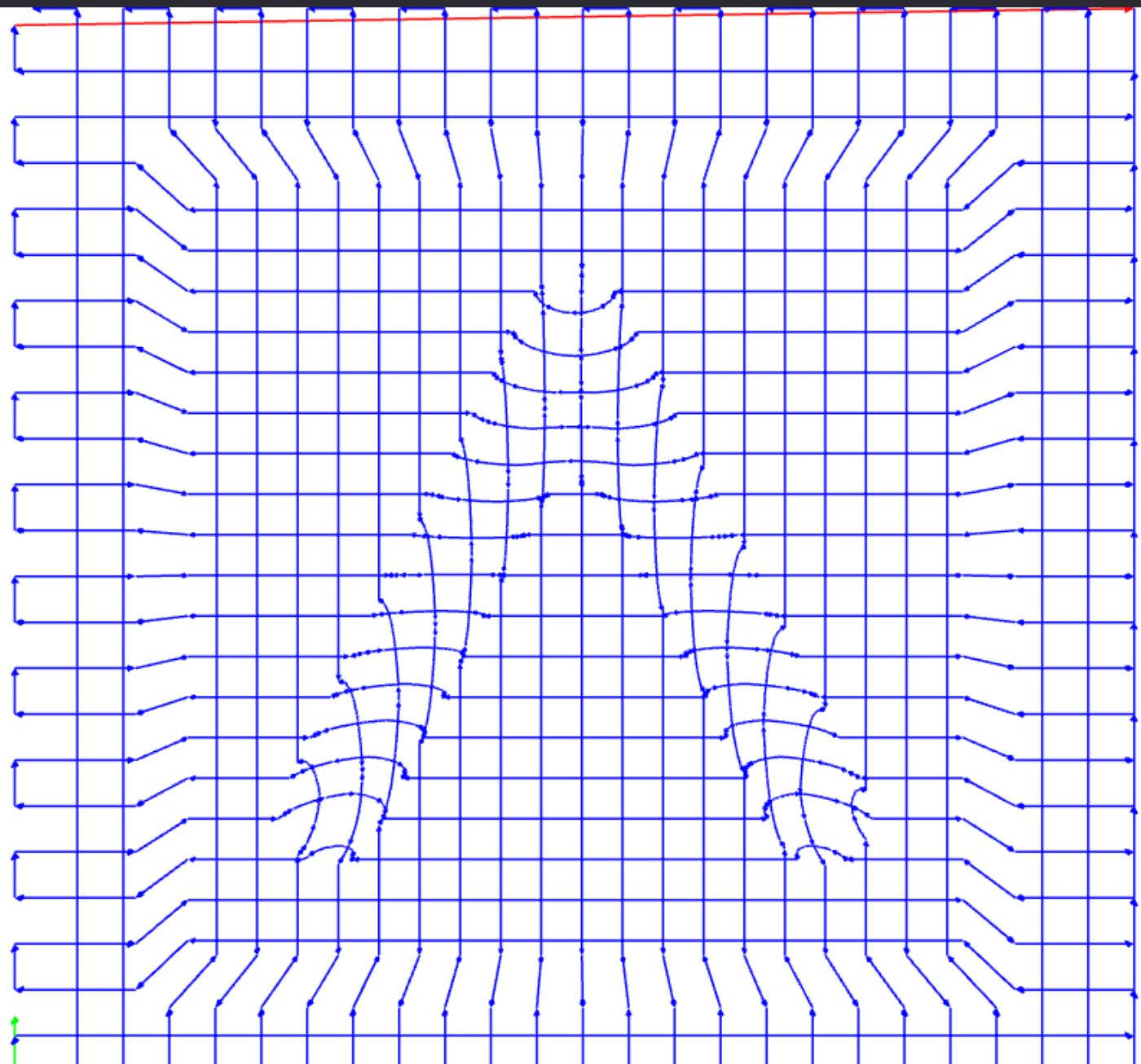
After importing the file, I went to the Mill raster 3d block and clicked calculate. in that block, theres also a really important setting called "stepover", which would be easier to understand if it was just called "quality". Basically, the lower it is, the longer your mill will take, but the better it will look.
After calculating with a stepover of .5 (rough pass) and .2(finishing pass), I took the files it
Random file fix
Because im using the program for general milling machines, it didn't follow some standards for othermill. the main problem was that it added in G54 to the start of the gcode. this changed offsets, but is Not supported on the othermill machines. In order to fix that, I simply deleted that line from the gcode files it exported. If you dont delete that, the othermill software gives you a giant warning about it not milling where you want it, then it won't mill where you want it.
Othermill
After getting the good gcode files, I sent them to the computer connected to the mill. I loading in a 1/8th ballnose for both passes, as my lab doesn't have 1/8th straight for the roughing pass. In the software itself, I only changed offsets to make sure that it milled on my wax, then started the mill. The rough pass took 10 minutes a 1.5 inch square basically, and the finishing took twice as long to cut with twice the detail.
Post Milling
After milling, I spent a bit sanding down the face. Due to the fact that we didn't have that straight bit, there were very small but visible channels going down the machine.
Molding
For the mold, we followed the same processes we did for our individual mold. We did end up using a different material, just because it was already out for another persons mold. We also used the quick release spray to create a layer between the wax and the molding material, which would make getting it out easier.
Milling + Molding result
Milling Advantages
- Wider range of materials: When using 3d printing, your limited to almost always plastics, but resins on a sls are also possible.
- Accuracy: A well tuned milling machine can surpass even the best accuracy of a 3d printer.
- Surface Finish: Thanks to the ability to due a finishing pass, you can make something on a milling machine that doesn't require any manual post processing
Design Files
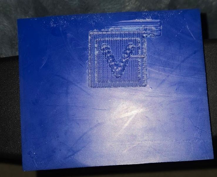
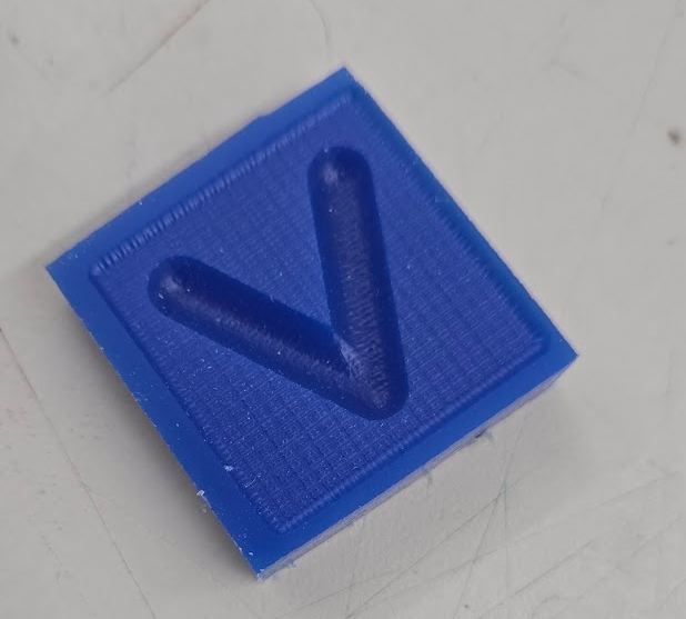
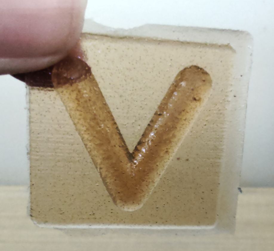
The design files of my window (which include the current design of the camera), as well as the small v object I made can be found here