Legacy System Design
Note: This page documents the initial design interaction of the project. While these designs were fully functional and innovative, they were ultimately replaced in the final version to improve reliability, safety, and simplicity. This system involved 4 interconnected custom boards and a distributed network of microcontrollers.
electronics: The 4-Board Ecosystem
My initial electronics design was a modular system consisting of four distinct boards working in unison.
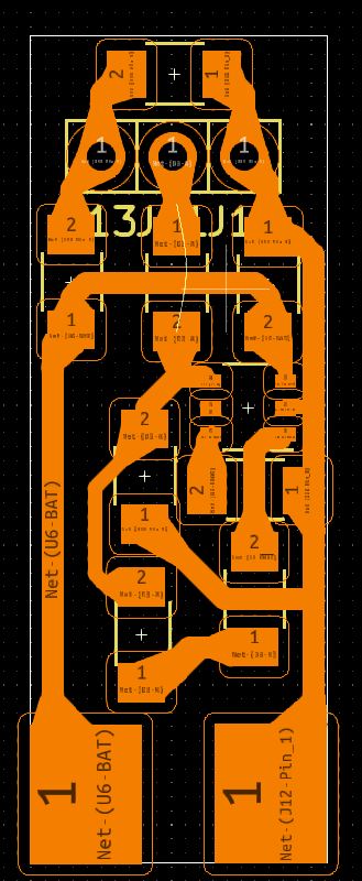
1. The Experimental Battery Board
I originally designed a battery management board based on the TP4057 chip (a variant of the popular TP4056). This board served as my introduction to PCB etching.
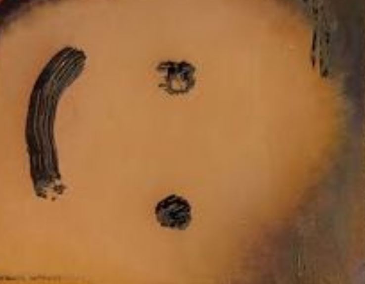
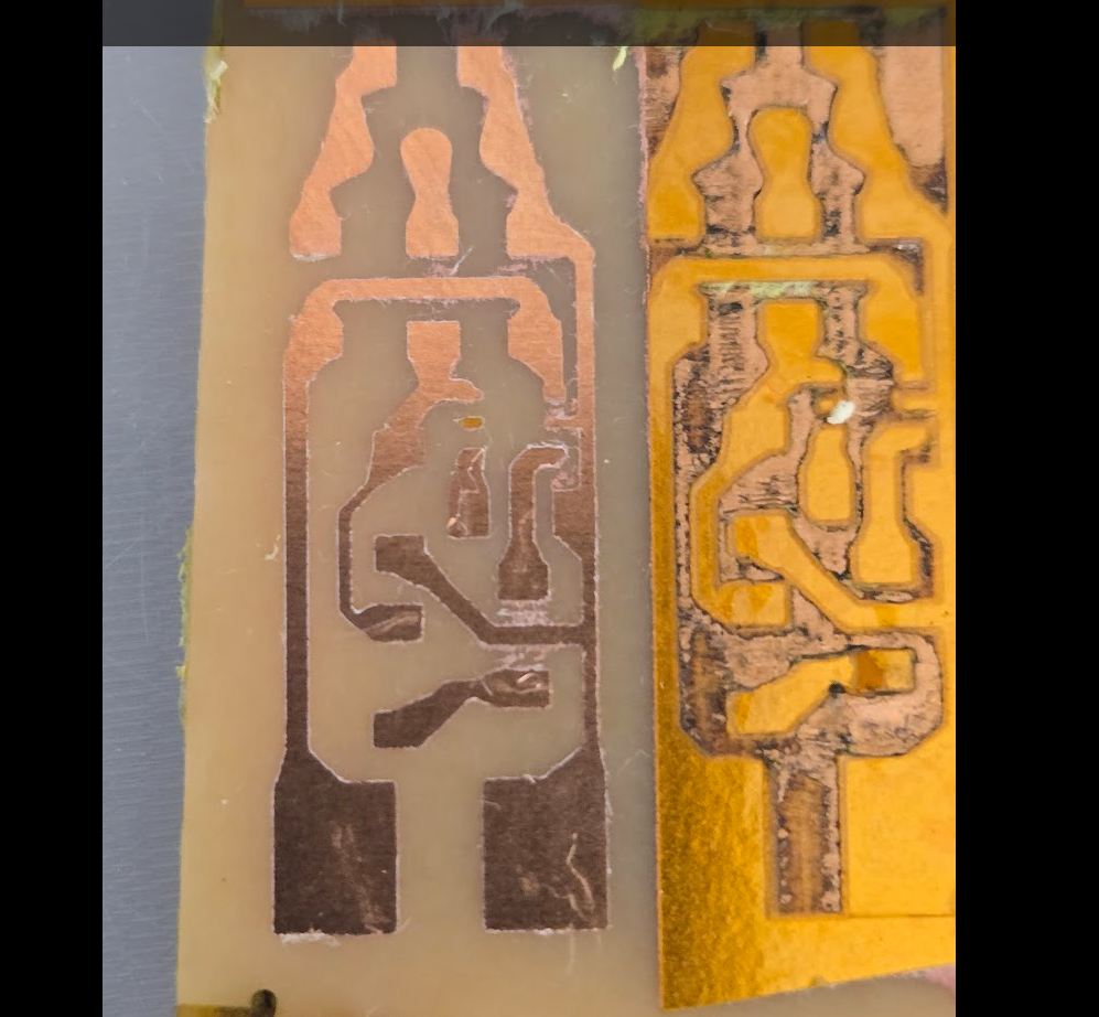
The Etching Process I used a "sponge and ferric chloride" method to etch the board. To verify the process, I started by drawing a simple smiley face with a sharpie. The results were surprisingly good, taking only 1-2 minutes to etch.
To make the actual traces, I discovered that Kapton tape makes an excellent mask. I laser-cut the negative of the board's copper layer into the tape, then used the sponge method to etch away the exposed copper.
Reason for deprecation: The risk of a short circuit or failure with lithium batteries was too high for a hand-etched board.
2. The Milled Microcontroller
I designed a custom ESP32-C3 breakout board intended for in-house milling. It was designed to be single-sided and compact, featuring about 6 supporting components (resistors, capacitors, voltage regulator).
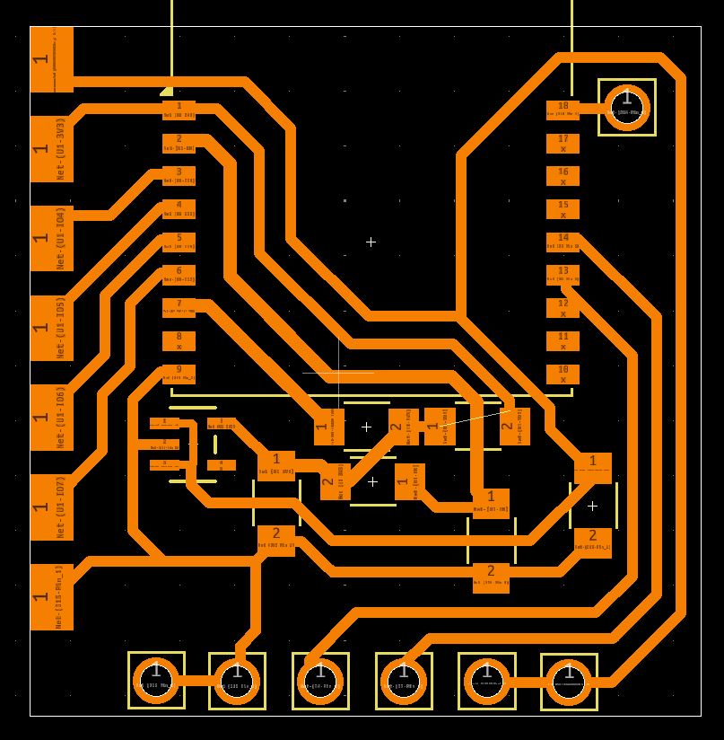
This board proved to be the most challenging. Milled boards often fail during soldering or operation due to tiny bridges or broken traces. I struggled to get the milled version working.
3. The Unconventional Stepper Driver
Because I was using a stepper motor combined with battery power, I needed a driver that was able to work with less than 8v. I found that the DRV8835 would work (2-12v, 1.5A max).
The unconventional part was the shape of it. I designed it to be soldered directly to the stepper motor pins (replacing the molex connector), with pads to connect to the microcontroller "wirelessly" (soldered directly on). This was the "coolest" part of the initial design but was complex to assemble.
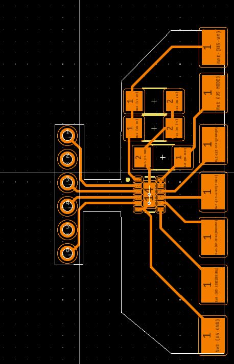
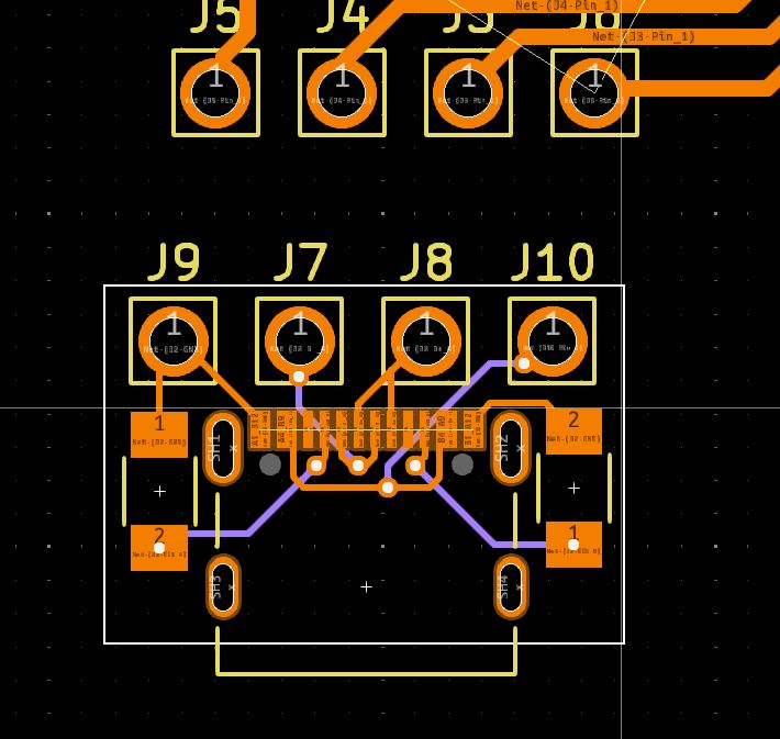
4. The USB-C Breakout
This was a continuation of the microcontroller board. I needed a USB-C module to communicate between the microcontroller and a computer. I decided to make it a separate board since the microcontroller had the potential to be made through milling/etching, and the USB-C port I used is too small to have a chance of being milled/etched successfully.
Legacy Programming Logic
The initial system relied on a distributed network of microcontrollers, including a Seeed Xiao ESP32-S3 Sense for video and my custom ESP32-C3 for motor control.
Camera & Networking
I used the Seeed Xiao ESP32-S3 Sense for wifi and camera support.
- Video Stream: The video stream used motion jpeg (rapid succession of pictures).
- MDNS: To communicate between microcontrollers without hardcoded IPs, I used MDNS (e.g., maestro.local).
- Communication: I used HTML forms to send data between the camera unit and the motor controller unit.
Stepper Control Logic
I largely had to write my own control logic. - Driver: A4988 / DRV8835. - Logic: Setting a pin high/low for direction and pulsing a step pin. - Integration: I combined the networking and stepper logic to create an interactive joystick webpage hosted on the ESP32 that could control the physical motors.