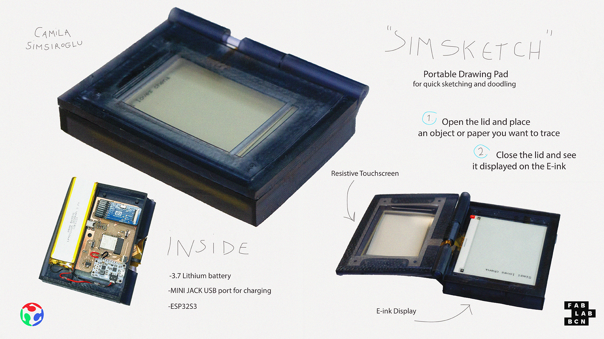
Portable Drawing Pad
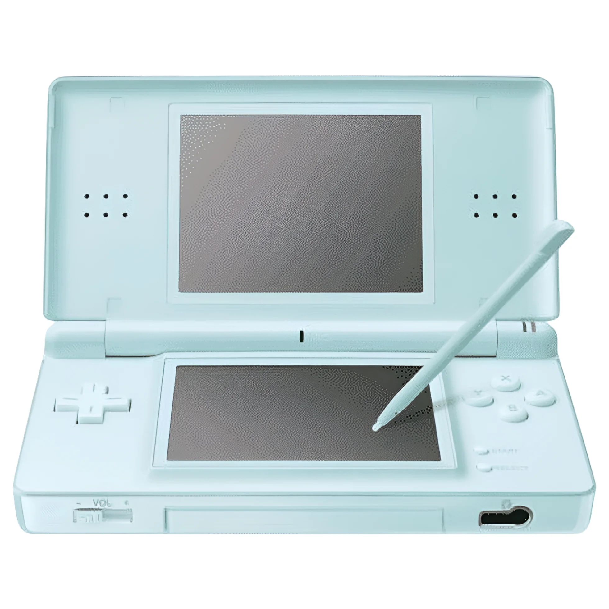
For the final project, I envision creating a portable drawing pad with a stylus. The device would allow users to draw and save their creations on the go, similar to a Nintendo DS or a Tamagotchi.
The idea is to provide an interactive and creative outlet, especially for people who enjoy sketching but need something compact and portable.
To create this device, I would 3D print a custom enclosure, integrate a touchscreen for drawing, and include an E-Ink display to showcase the artwork. The functionality of the stylus and saving system would be powered by embedded electronics. Additionally, navigation buttons would let users easily scroll through their saved sketches and doodles.
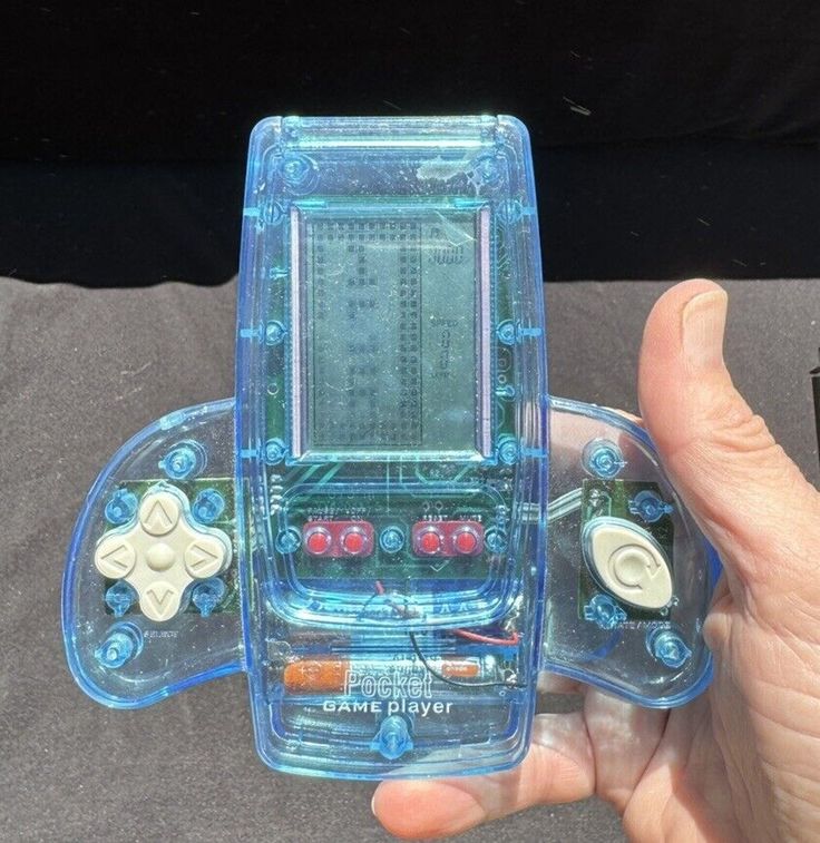
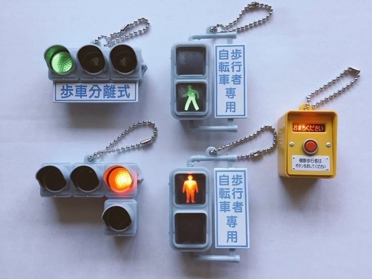
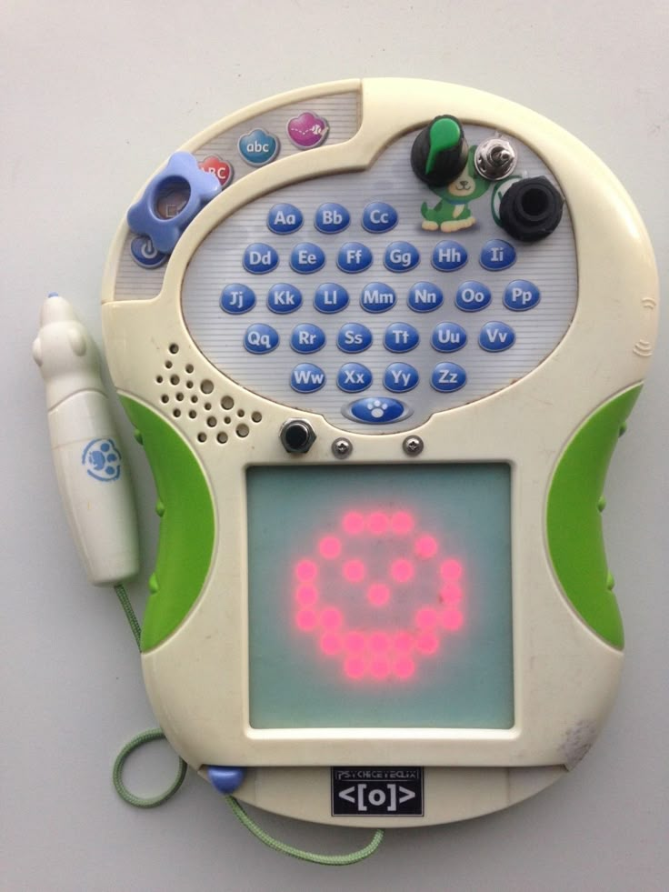
Some references!
This setup has the potential to become a compact, go-to tool for capturing creative ideas on the fly for quick sketches, doodles, or even creating full designs while on the move.
Schedule
I don't want to mess up my timing so I am aiming for this:
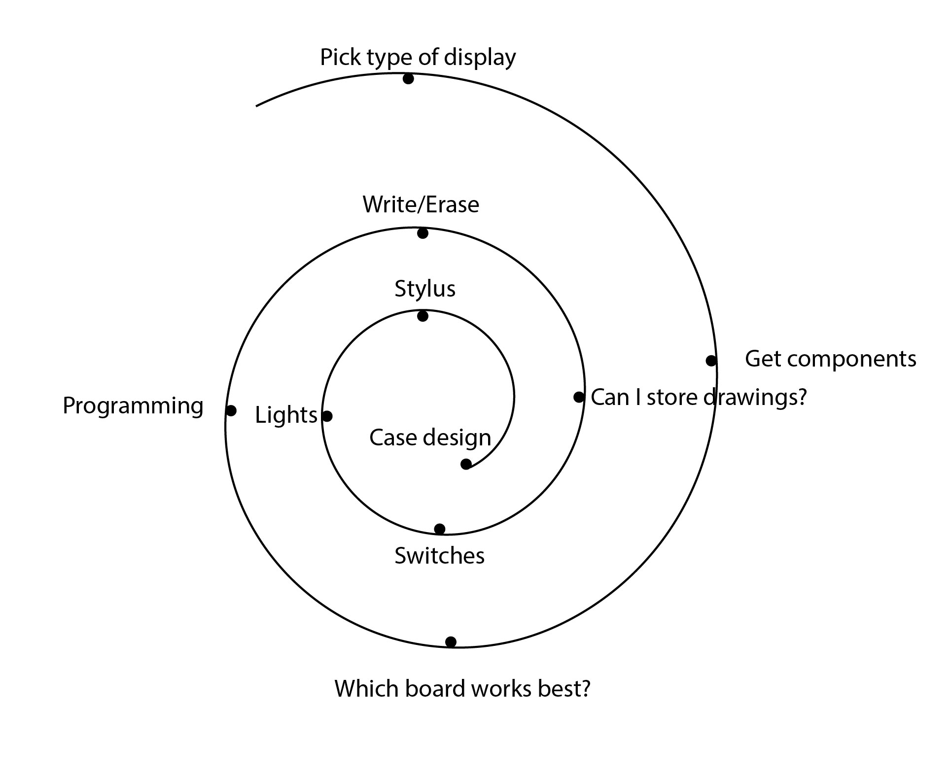
Update: This has changed into this schedule.
Wednesday May 14th: Get readings grom touchscreen. ✓
Wednesday May 22th: Get the display working. ✓
Wendesday May 28th: Communicate both components. ꩜
Wednesday June 4th: Assemble enclosure. ꩜
The biggest challenge in my project has been managing my own expectations. When I joined the course, I let my imagination run wild, which is great for creativity, but it’s also important to recognize my current limitations.
This is just the first version, not the final product. With tight deadlines, I’ve accepted that my full vision won’t come to life in one try. After Fab Academy, I plan to collaborate with other professionals to bring it closer to what I envision.
Type of Display
I really enjoy the feel of paper-----> I want to resemble that appearence-----> I'll go with an E-ink Display. ✓
I began researching and gathering information about these types of displays, which I had never worked with before. I noticed that tactile E-ink displays were not widely available, but I knew they existed from my experience with devices like the Kindle and the ReMarkable, which support text, drawing and sketching.
I came upon this discussion on Reddit where someone pointed out the idea of a two-part E-Ink display. What this means is that while I may not find E-ink displays that are touchscreens themselves, I can use a tactile glass screen overlay and make it communicate with the display.
🏁 So let's head over and reaserch some touchscreens!
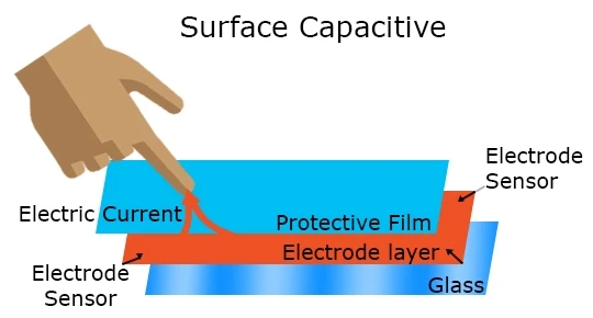
I learned that there are two types of technologies for screens that function differently.
Capacitive screens detect touch through changes in the electric field, allowing for multi-touch and offering better durability and clarity. They require conductive input (like fingers) and are common in modern smartphones.
Resistive screens work by pressure; two layers of conductive material make contact when pressed, registering touch. They're cheaper and work with any object, including a stylus, but have lower clarity and are less responsive than capacitive screens.
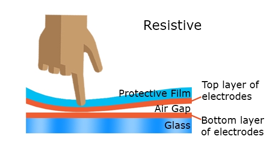
I find the stylus to be a very important part of this project since it contributes to the enjoyment and general feel of drawing. Which is why I went for the resistive screen.
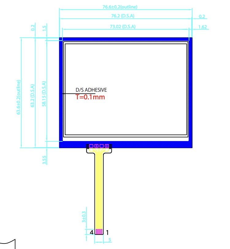
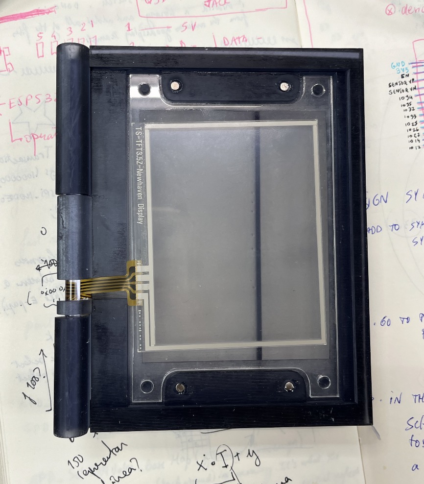
I chose this one from DigiKey, the TS-TFT3.5Z Touch Screen Overlay with a 4-Wire interface, as you can see in its not so detailed datasheet.
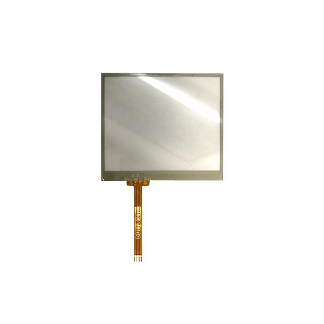
Then I went through this documentation that helped me understand how it actually worked.
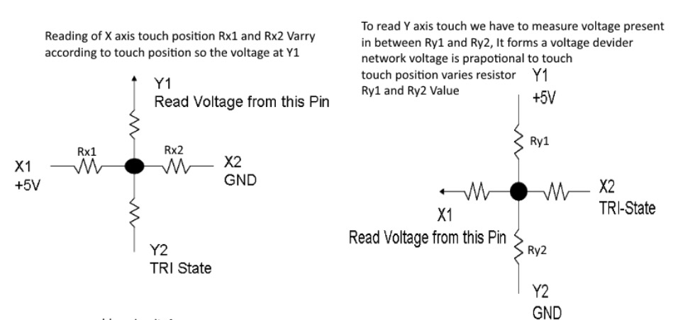
This left me with a lot of questions, like; how did I not get the same readings on the X axis if I drew an horizontal line?
Turns out, when measuring X, the exact Y position doesn’t matter—as long as the Y-layer is providing some voltage.
The Y-layer is just acting as a voltage source (creating a gradient from 5V at the top to 0V at the bottom).
The X-layer "picks up" the voltage at the touch point, no matter the height (Y-value).
The Arduino reads this voltage and maps it to an X position.
So, even though you might think, "Wait, isn’t the Y-voltage constant across an X-line?" what actually matters is that the X-layer is using that Y-voltage to figure out where the touch is horizontally.
Readings
I went ahead and soldered the connections to wire it up with my Barduino. Then
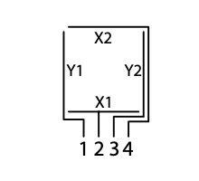
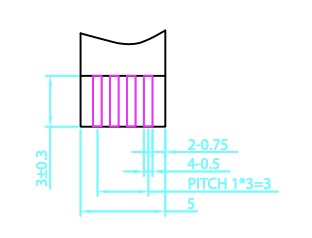
Following these specifications of the datasheet I was able to figure out the positions of the pins.
I tried the following Code to get some readings:
void setup() {
    Serial.begin(9600);  // Open serial communication
}

void loop() {
    // Read Y coordinate
    pinMode(A0, INPUT);
    pinMode(A1, INPUT);
    digitalWrite(A0, LOW);
    pinMode(A3, OUTPUT);
    digitalWrite(A3, HIGH);
    pinMode(A2, OUTPUT);
    digitalWrite(A2, LOW);
    int y = analogRead(A1);

    // Read X coordinate
    pinMode(A2, INPUT);
    pinMode(A3, INPUT);
    digitalWrite(A2, LOW);
    pinMode(A1, OUTPUT);
    digitalWrite(A1, HIGH);
    pinMode(A0, OUTPUT);
    digitalWrite(A0, LOW);
    int x = analogRead(A3);

    // Send the coordinates over Serial
    Serial.print(x);
    Serial.print(",");
    Serial.println(y);

    delay(700); // Smooth drawing
}
The values returned in the serial monitor were hard to figure out.
Sudden Thoughts and Epiphanies
It was certainly a challenge to pick a the size of the transparent touchscreen. Especially because I needed it to match the e-Ink display that would go under it.
Transparent... Interesting... (˵ ¬ᴗ¬˵)
This means I can see through----> Use it as a scanner.
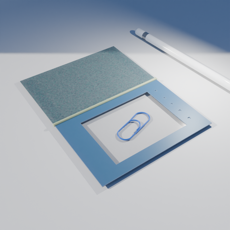
By separating the Touchscreen Overlay from the Display I can place items/drawings/notes and trace them.
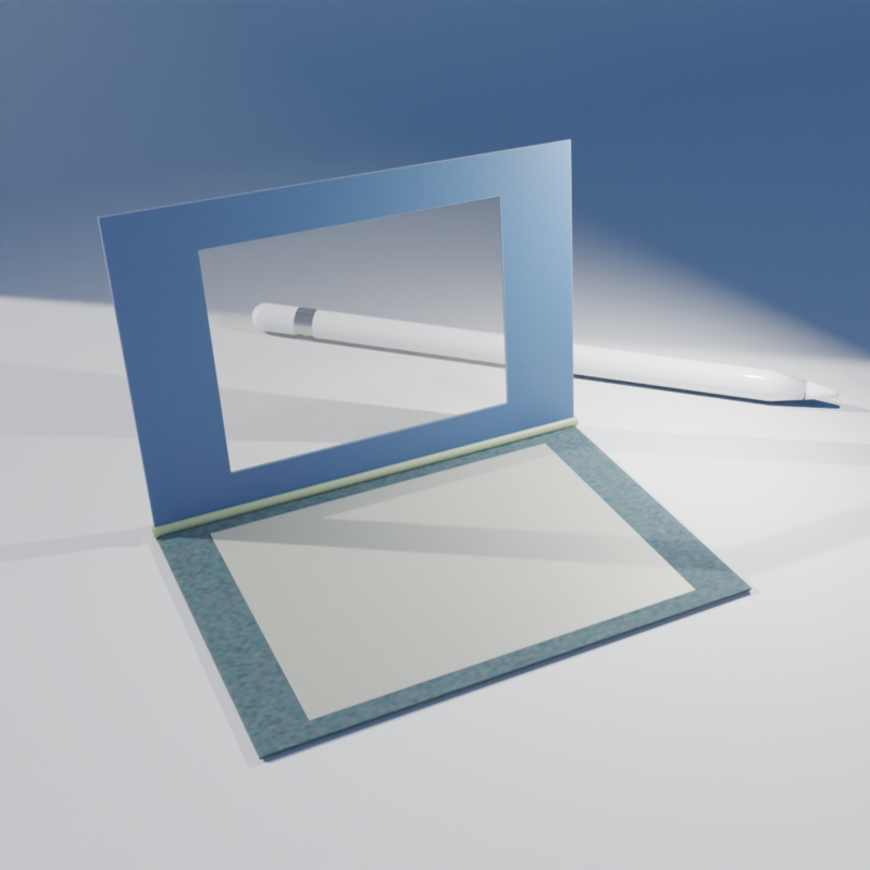
Once done, I can remove it and join the components together (like closing a book) and see the results. Or alternatively, I can use it while closed to draw directly on the e-Ink display in real-time.
That's it ! That will be my final project. A portable scanner/drawing pad.
Touchscreen
I order this capacitive touchscreen hoping for more precision in my readings. Unfortunately, it was MXT336T based. And I was not able to find a library that could manage this chip, least one that was Arduino friendly.
I kept looking for other components like this that were Arduino friendly but I could not find any that were not linked to a display. Like the ESP32_TOUCHSCREEN.library for example.
So I had to re-trace my steps and get back trying with a resistive touchscreen.
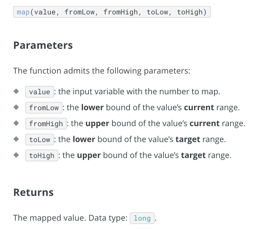
As mentioned earlier, I initially struggled to get accurate readings from the resistive touchscreen. However, after proper wiring and remapping the input values, I was able to calibrate it to a range that worked well for me.
Even better, thanks to Arduino's mapping function, I can easily readjust it anytime to suit my needs.
I determined the parameters by touching each of the four corners of the screen and then translating those readings into an approximate ratio based on the physical dimensions of the touchscreen — from 71.8 mm by 52.5 mm to a proportional scale of 100:70.
Adjusted code:
#define Y1 = 1
#define X1 = 2
#define Y2 = 4
#define X2 = 5


void setup() {
    Serial.begin(9600);  // Open serial communication
}

void loop() {
    // Read X coordinate
    pinMode(2, INPUT);
    pinMode(5, INPUT);
    digitalWrite(2, LOW);
    pinMode(1, OUTPUT);
    digitalWrite(1, HIGH);
    pinMode(4, OUTPUT);
    digitalWrite(4, LOW);
    int x = analogRead(2);
   x = map(x, 3700, 280, 1, 100);
    // Read Y coordinate

    pinMode(1, INPUT);
    pinMode(4, INPUT);
    digitalWrite(1, LOW);
    pinMode(2, OUTPUT);
    digitalWrite(2, HIGH);
    pinMode(5, OUTPUT);
    digitalWrite(5, LOW);
    int y = analogRead(1);
   y = map(y, 3700, 500, 1, 70);

    // Send the coordinates over Serial
    Serial.print(x);

    Serial.print(",");
    Serial.println(y);

    delay(700); // Smooth drawing
}
And to try things out I experimented with connecting it to Processing to visualize the movement data from my readings.
E-Ink
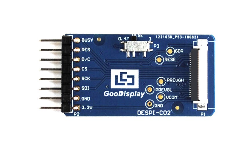
Back to the display, I decided to go with this 4.2 inch E-Ink display, the GDEY042T81 by GooDisplay.
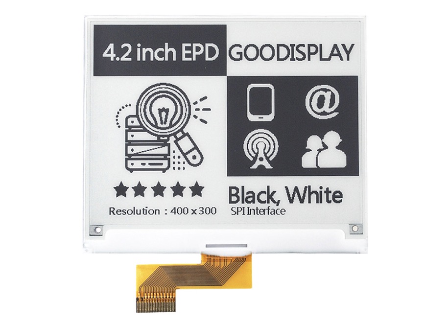
The main reason I chose this model is that its size matched my needs, and it came with comprehensive documentation and resources readily available for download—such as usage guidelines, GDEY042T81 specifications, driver details, and Arduino examples for various MCUs like the ESP32.
Very GooDisplay hehe.
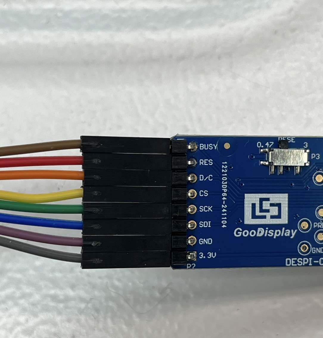
In able to communicate with it, I needed a proper driver that could manage its chip. So I bought this 24 pin serial ePaper screen HAT adapter board, DESPI-C02. Also by the same manufatures and a lot of information avaiblable.
To begin testing the E-Ink display, I used the sample code provided by the manufacturer and ran it on my Barduino board.
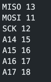
Before diving into the display functionality, I wanted to confirm that the hardware pin mappings were correct and obtain the SPI pin designation for a ESP32 S3(as stated in this discussion).
To do this, I uploaded a simple Arduino sketch that prints the names and corresponding numeric values of the key pins (such as MISO, MOSI, SCK, and analog pins A14–A17) to the serial monitor. This allowed me to verify that the Barduino's internal pin definitions matched what the manufacturer’s library expected.
Here’s the code I used for checking the pin values:
void setup() {
  // put your setup code here, to run once:
  Serial.begin(115200);
  delay(1000);

}

void loop() {
  // put your main code here, to run repeatedly:
  Serial.print("MISO ");
  Serial.println(MISO);
  Serial.print("MOSI ");
  Serial.println(MOSI);
  Serial.print("SCK ");
  Serial.println(SCK);
  Serial.print("A14 ");
  Serial.println(A14);
  Serial.print("A15 ");
  Serial.println(A15);
  Serial.print("A16 ");
  Serial.println(A16);
  Serial.print("A17 ");
  Serial.println(A17);
  delay(5000);
}
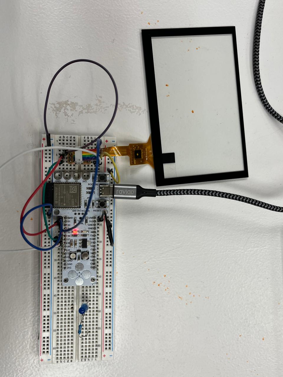
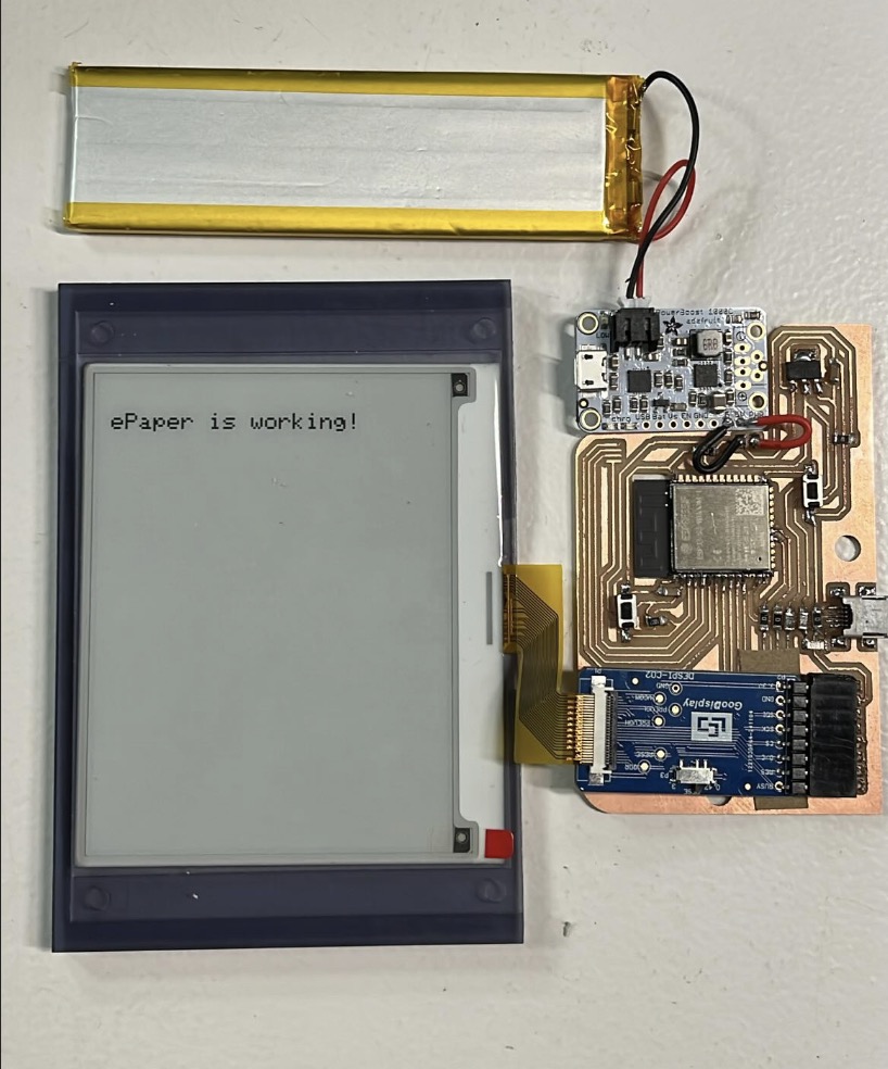
With this out of my way I wired the display to the driver and the driver to my barduino on the breadboard.
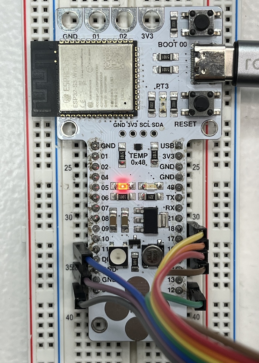
Ran the code provided by the manufacturer and it worked!
I had confirmed that the display was functioning properly and the driver I picked was compatible.
After that, I moved on to testing image rendering by uploading a bitmap. Which looks a little bit like this:
const unsigned char Num[10][256] = {
//0
{
0XFF,0XFF,0XFF,0XFF,0XFF,0XFF,0XFF,0XFF,0XFF,0XFF,0XFF,0XFF,0XFF,0XFF,0XFF,0XFF,
0XFF,0XFF,0XFF,0XE0,0X03,0XFF,0XFF,0XFF,0XFF,0XFF,0XFC,0X00,0X00,0X1F,0XFF,0XFF,

and so on...
To prepare the image, I used an online tool to convert it into a compatible bitmap format. Below are the settings that worked best for my display.
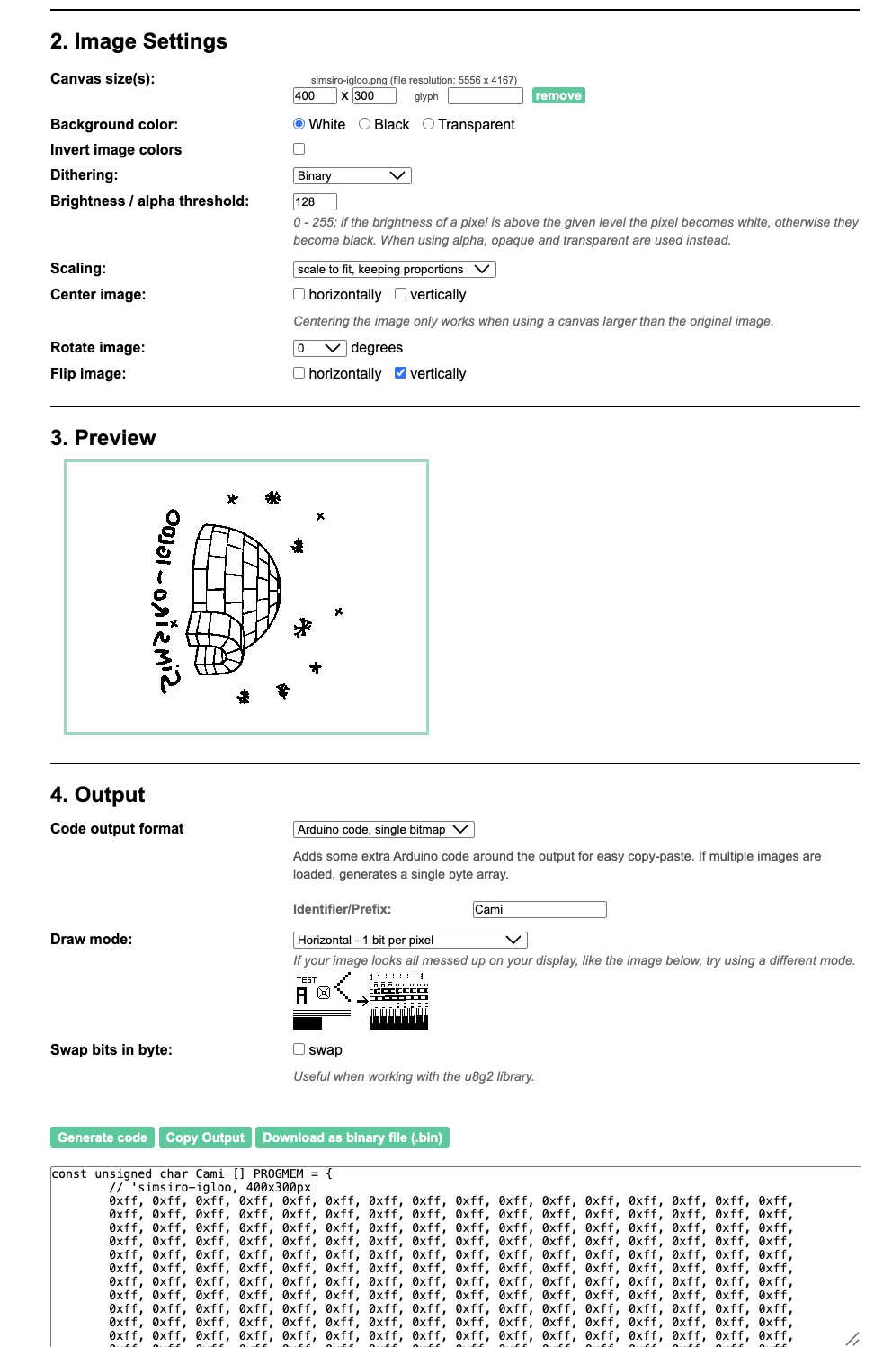
I added the bitmap const unsigned char into the Ap_29demo.h file that came with the sample file.

Uploaded and this happened!
With the help of my instructors, we were able to tweak the manufacturer's example code and integrate it with the resistive touchscreen input. This allowed us to read and store an array of 1000 positions, which were then displayed and retraced on the e-ink screen.
This code relies on two main libraries: GxEPD2 for controlling the e-paper display, and Adafruit_GFX for handling graphics rendering.
It takes advantage of FreeRTOS on the ESP32 by using xTaskCreatePinnedToCore() to run the readPositions() function on the second core. This allows touch position data to be read continuously in the background without blocking the main program.
Touch coordinates are obtained using getxPos() and getyPos(), which read the analog values via the ADC and map them to the screen’s coordinate system.
I learned that FreeRTOS* Free Real-Time Operating System is a lightweight OS built into the ESP32 framework and it supports multitasking, meaning it can run multiple tasks or functions once, ideal for managing background work.
xTaskCreatePinnedToCore(
  readPositions,    // Task function
  "readPositions",  // Name for debugging
  10000,            // Stack size (bytes)
  NULL,             // Parameters (none here)
  1,                // Priority (higher = more important)
  NULL,             // Task handle (unused)
  1                 // Core to pin to: 0 or 1 (ESP32 has 2 cores)
);
This line launches readPositions() as a FreeRTOS task pinned to core 1, separate from the Arduino loop() which runs on core 0 by default.
This means that the main drawing/display code runs on core 0 and the continuous position reading (readPositions) runs in parallel on core 1, allowing non-blocking data acquisition without slowing down screen updates. It also avoids interference with SPI/e-paper refresh.
Embedded Electronic
I began planning the electronic components for the project. I decided to use the ESP32-WROOM-1 module, which is readily available in our lab.
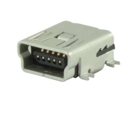
Along with it, I'll incorporate the DESPI-C021 driver and a mini jack USB connector for programming the microcontroller.
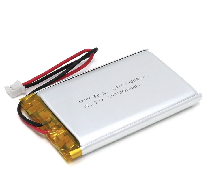
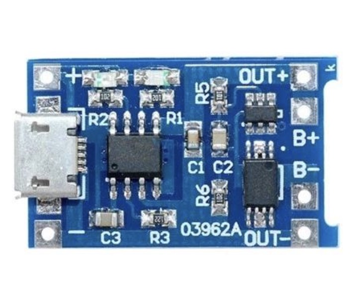
For power supply, I'll include a 3.7V 2000mAh LiPo battery and a TP4056 battery management module to handle charging.
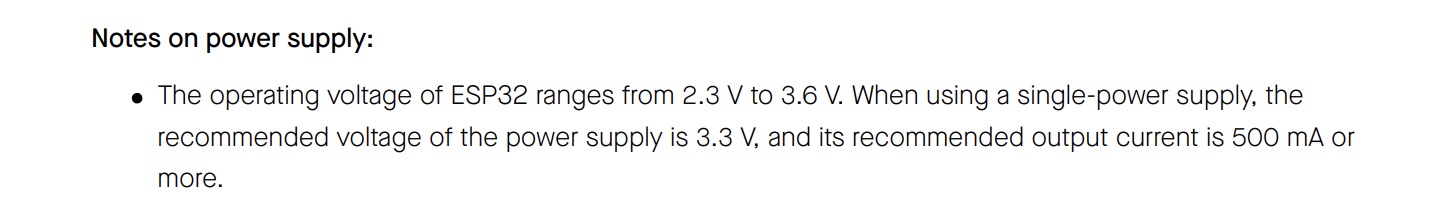
I'll also need a voltage regulator, since the ESP32-WROOM-1 operates within a voltage range of 2.3V to 3.6V. As seen in the datasheet.
These components cover everything I need for the first version of the PCB and now the schematics are looking like this:
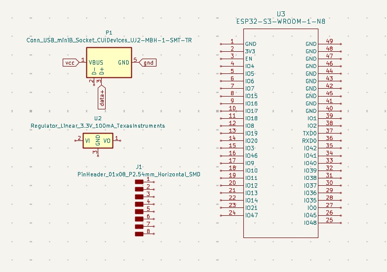
And the PCB like this!
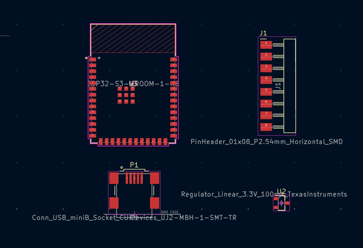
You can download the Kicad Project to see this in more detail!
I milled the copper board using the Roland SMR-20 and generated the toolpath with the Mods project.
Next came the soldering, which was quite challenging since I had small components and tiny pads (eg. ESP32-S3-WROOM-1 and Mini USB type B).
After everything was added, the board was looking like this:
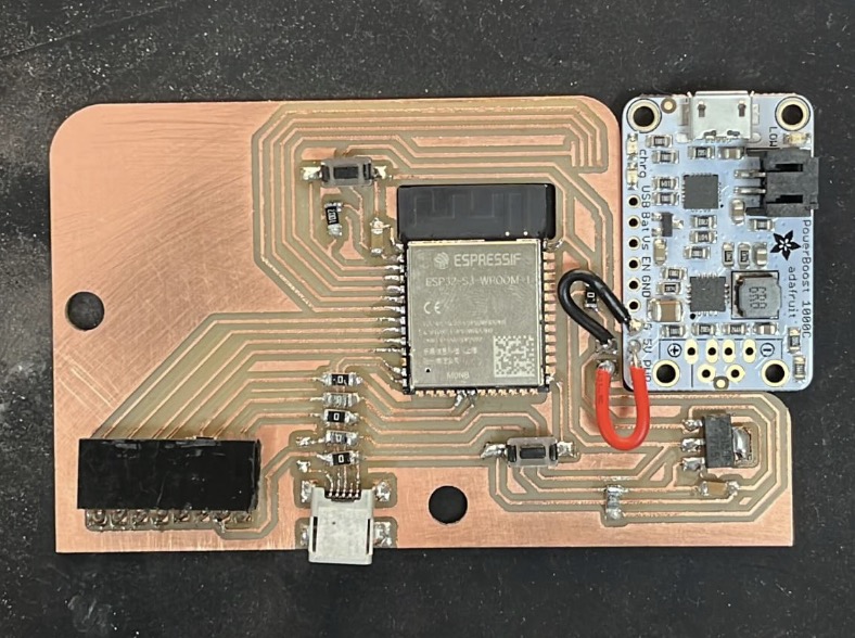
I added two push buttons to RESET and BOOT the board in case I ran into any issues while programming.
You may have noticed that the TP4056 battery management module was replaced with an Adafruit PowerBoost 1000 Charger. This change was necessary due to an issue I encountered while trying to power the board.
With the TP4056, the fully charged battery outputs a maximum of 4.2V. However, the voltage regulator I’m using has a minimum dropout voltage of 1.2V.

Since the ESP32 runs at 3.3V, the regulator requires at least 4.5V (3.3V + 1.2V) input to function correctly.
To solve this, I switched to the PowerBoost module, which steps up the battery’s 3.7–4.2V output to a stable 5V. This ensures that the voltage regulator receives sufficient input to reliably output 3.3V for the ESP32.
With this out of the way I tried all the components together. Withouth the resistive touchscreen which would be added once the system was integrated for assembly reasons.
Integrated System
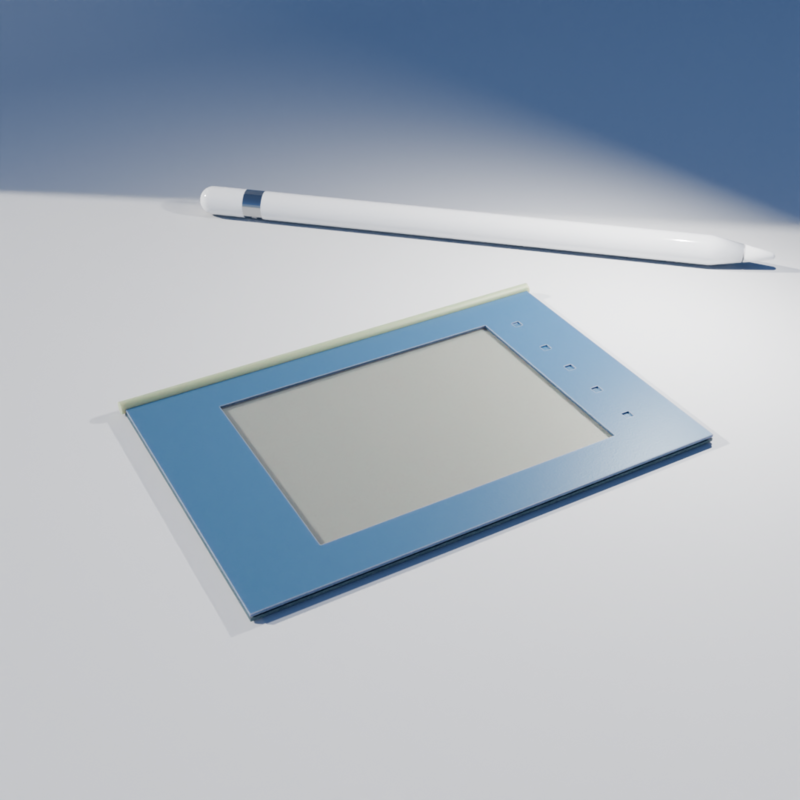
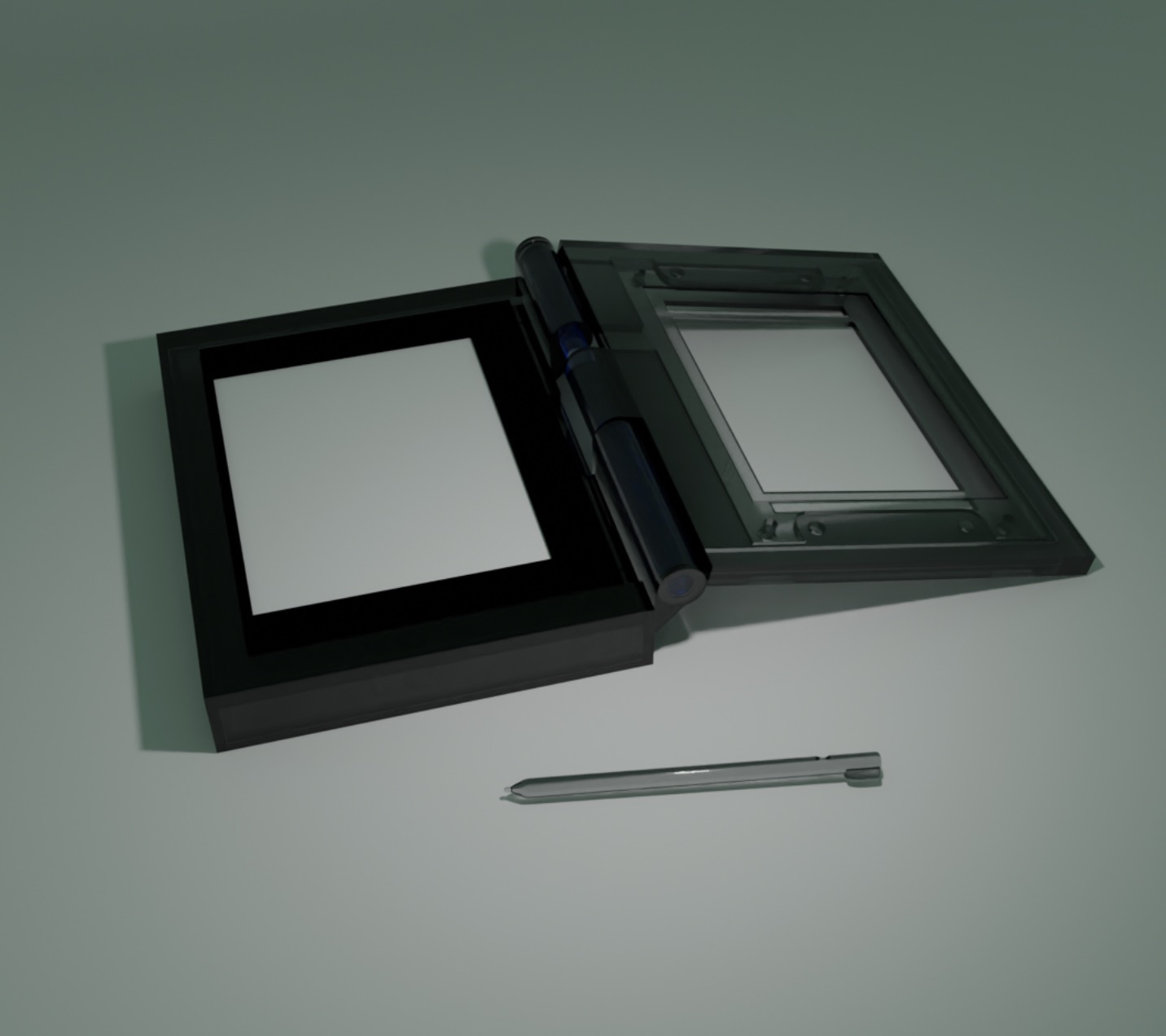
With the board completed, it was time to assemble all the components. I designed the entire project in Blender, and after at least three iterations everything came together looking like this:
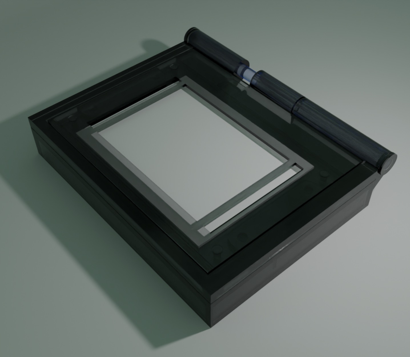
The most challenging part was designing the hinge mechanism. I chose to create a tunnel running through both the top and bottom sections at the same height. Then, I inserted an acrylic cylinder through these tunnels, which held the parts together while still allowing rotation.
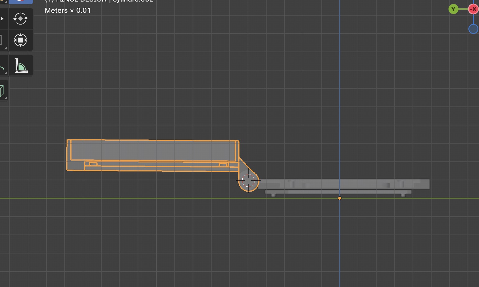
To keep the cylinder from sliding out, I added two side lids and glued them in place, securing the hinge without restricting its movement.
I resin printed all the parts in a "smoky resin" on our local SLA printer, the Elegoo Saturn 4.
I also added an acrylic layer that I laser cut to adhere the resistive touchscreen.
This was embedded in the superior part of the enclusure like this:
Once everything was set up, I assembled it and here’s how it turned out!
Just as I dreamed it. (∩˃ω˂∩)
Presentation
This is my final project.
You can see the developement and results here.
Thank you ;)
See ya,
Simsi