Week 5
Finally! In this week’s program we got our hands into additive manufacturing. It's all about bringing digital objects into the physical world through 3D printing and turning real objects into digital models with 3D scanning. We explored various materials and slicing software, as well as different printing mechanisms.
Additive vs. Subtractive Manufacturing
- Additive manufacturing, commonly known as 3D printing, works by depositing material layer by layer to build an object. This process allows for the creation of highly complex and intricate shapes, including internal structures and geometries that would be impossible to achieve using traditional manufacturing methods.
- Subtractive manufacturing involves starting with a solid block of material and removing sections through cutting, milling, or carving to create the final shape. CNC machines, laser cutters, and lathes fall into this category.
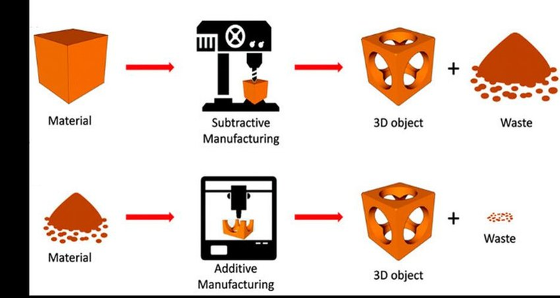
Subtractive methods offer high precision and material strength, however they are often limited in terms of geometry and waste more material compared to additive techniques.
Types of 3D Printers
Different types of 3D printing methods suit different results. You might need a smooth surface for aesthetics, precise joints for assembly, or strong materials for durability. Speed can also be a priority, especially for rapid prototyping. Also, each technology is compatible with different materials, making the choice dependent on both the final use and the printing process.
Fused Deposition Modeling
FDM* Fused Deposition Modeling melts plastic filament and extrudes it layer by layer. It is affordable and great for basic prototypes but leaves visible layer lines.
Stereolithography & Selective Laser Sintering
SLA* Stereolithography uses UV light to cure liquid resin, producing detailed, smooth prints but requiring post-processing.
SLS* Selective Laser Sintering fuses powdered materials like nylon or metal, creating durable, complex parts without support structures.
Material Properties in 3D Printing
Choosing the right material depends on the strength, flexibility, and heat resistance needed for your print. PLA* Polylactic Acid is the most common for FDM printing—easy to use and detailed, but not heat-resistant. So you can melt it in lost wax technique!
In SLA printing, castable resins are specifically designed for applications like jewelry making or investment casting. These resins can burn off cleanly during casting, leaving behind minimal residue, making them ideal for creating detailed molds and precision cast parts.
ABS* Acrylonitrile Butadiene Styrene is stronger and more impact-resistant, though it requires careful printing to avoid warping.
For a balance between durability and ease of printing, PTEG* Polyethylene Terephthalate Glycol-modified is a solid choice.
TPU* Thermoplastic Polyurethaneon the other hand, offers flexibility for rubber-like parts. Nylon is valued in industrial applications for its high strength and wear resistance, and SLA resins can be formulated to be rigid, flexible, or biocompatible.
If you need heat resistance and durability, go for ABS or Nylon. For simple prototypes, PLA remains a reliable option.
3D Scanning Methods and Applications
3D scanning is a process that captures the geometry of real-world objects to create digital models. Most common techniques:
-
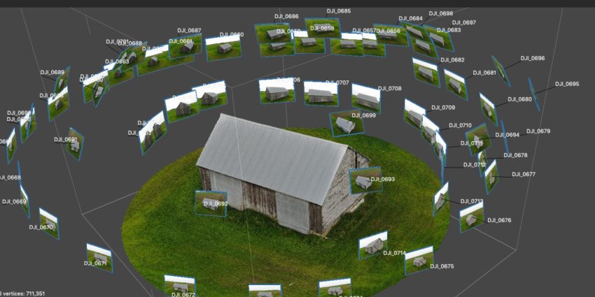
Photogrammetry: Uses multiple photos taken from different angles to create a 3D model; requires good lighting and textured surfaces. LiDAR (Light Detection and Ranging): Uses laser pulses to measure distances and create a detailed point cloud, available in some smartphones for large objects.
-
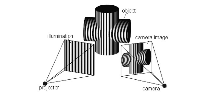
Structured Light Scanning: Projects light patterns onto objects to measure distortions, providing high accuracy for industrial and professional applications.
-
Handheld Infrared Scanners: Capture medium-detail objects, ideal for scanning people, organic shapes, or mechanical parts.
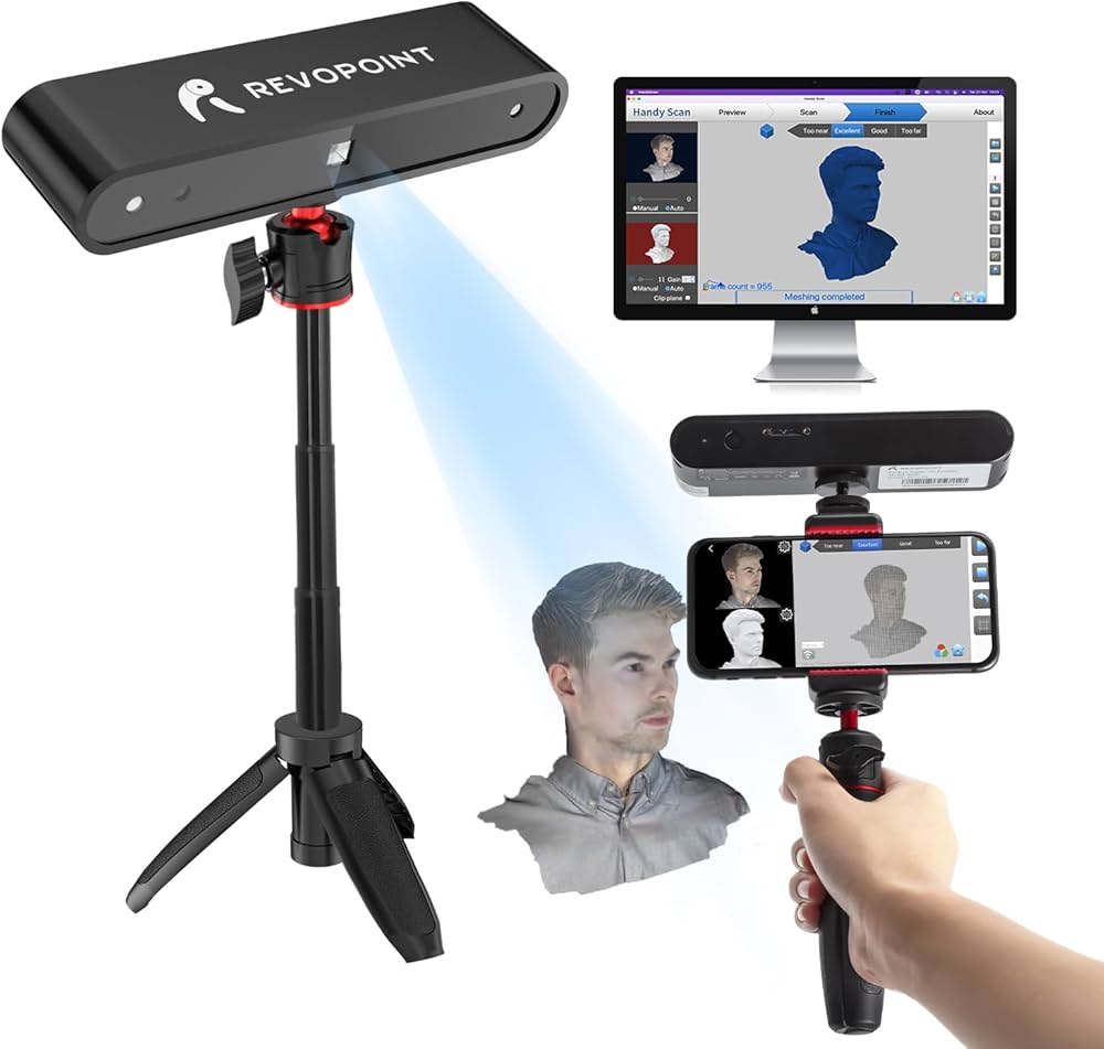
! Most scans require post-processing to clean up noise, fill in missing areas, and optimize for further use.
Mesh Repair and Optimization
After scanning an object, the resulting 3D model often has imperfections, such as missing geometry, holes, or rough surfaces. To prepare it for use, mesh repair tools are needed. Software such as Meshmixer allows users to smooth out rough areas, close gaps, and simplify the model by reducing unnecessary polygons. This process, known as decimation, is especially important for ensuring that the file is optimized for 3D printing.
Many scans also contain excess noise or floating points that need to be manually removed. Once the mesh is cleaned up, it must be converted into a watertight model, meaning that there are no open edges or gaps that would cause printing errors.
Trying out the Revopoint
In our local lab, we have a Revopoint scanner and a Kinect device, which has a pretty cool history. So I went ahead and attempted to recreate a level measuring instrument using Revo Scan 5, Revopoint’s software designed to process data from the scanner.
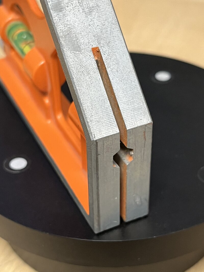
The object in question:
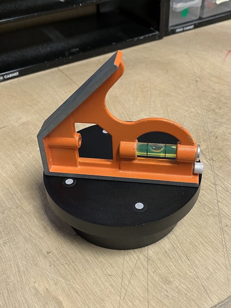
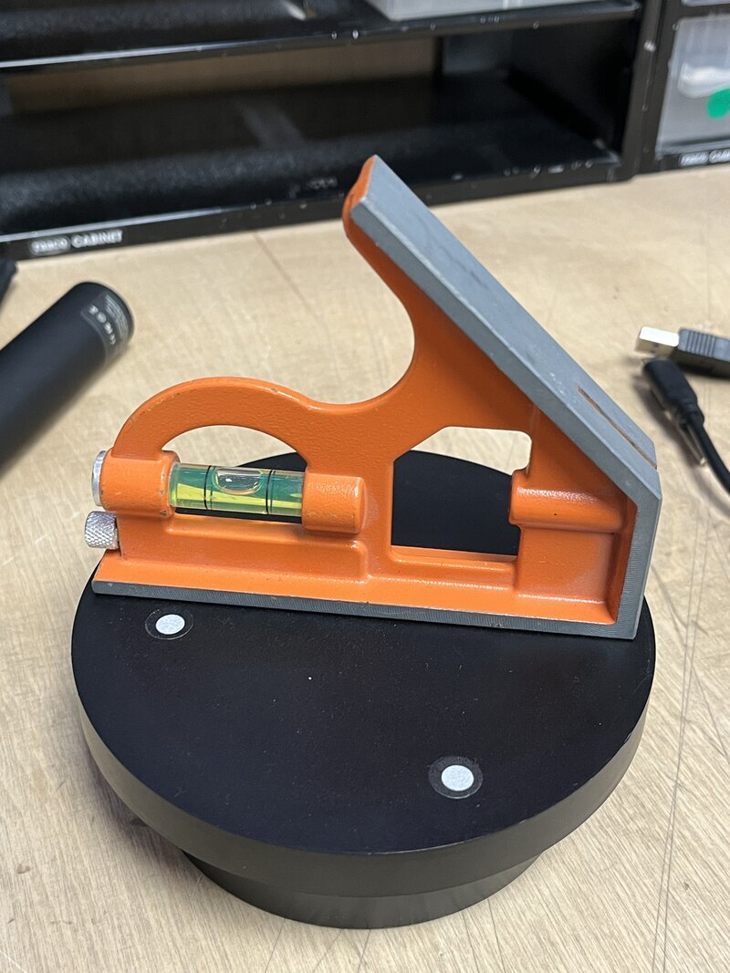
Notice that it's placed on a rotating surface with reference points!
I opened Revo Scan 5 and created New Project and then rest was pretty intuitive. If your scanner is correctly plugged, the software will recognize it automatically. Now and all you have to press is PLAY and the Revopoint will start taking pictures and constructing the model.
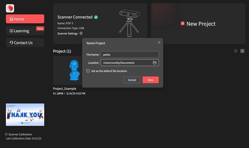

Remember to click on COMPLETE once the object has made a 360º turn. Otherwise it will start overwriting information on top of your scan. This was the result in its 3 modes: Raw, Fused and Meshed.

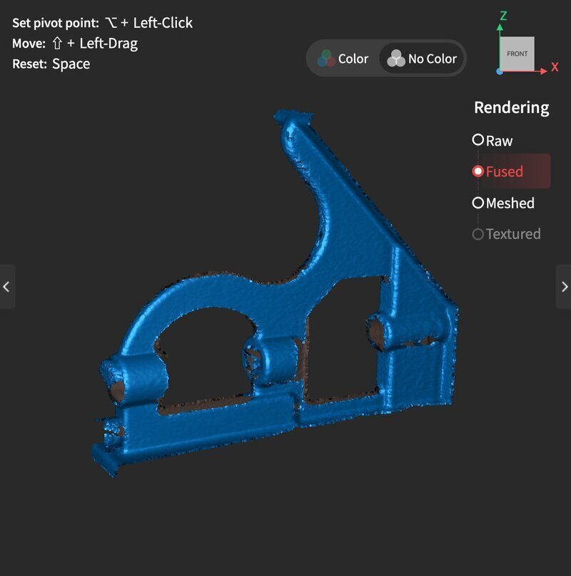
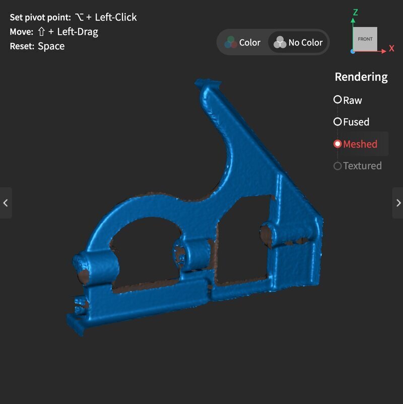
Not bad… but not great either. Even after applying a mesh repair within the software, the object wasn’t watertight. I can also clearly see the weak points of 3D scanning. Especially around the transparent cylinder, where nothing was captured at all, and on the slightly reflective metal.
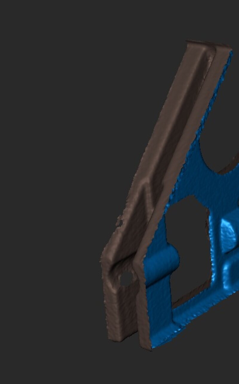
If I where to print this, I would continue this process in Blender. Remeshing it with hard-modelling techniques, such as applying objects to fill the gaps until I get a watertight model.
File Formats for 3D Printing
- STL (Stereolithography): The most common format for 3D printing, representing models as triangular surfaces but lacking color and material information.
- OBJ: Supports color and texture information, suitable for more advanced 3D printing applications.
- AMF (Additive Manufacturing File Format): Supports multiple materials and colors in a single file, though less commonly used than STL.
- G-code: A file format that contains the specific instructions for the 3D printer to build the object layer by layer.
3D Printing Process and Optimization
Before sending a 3D model to print, it must be sliced into layers using specialized software like Cura, PrusaSlicer, or Chitubox. This process generates the necessary toolpaths for the printer.
Important slicing settings include layer height, which controls the resolution of the print, and infill percentage, which determines the internal structure and strength of the object.
Additionally, support structures may be required for overhanging areas that would otherwise print in midair. These supports are removed after printing, but they add extra material and post-processing time. Proper print orientation and bed adhesion techniques, such as using a heated bed or adhesive surfaces, can also help improve success rates.
... and on this week schedule!
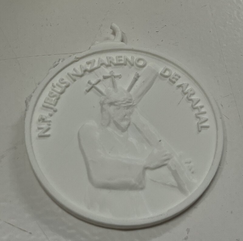
On the group assigment we were set to test the design rules of our local 3D printers: minimum wall thickness, overhangs, bridges, infill patterns, etc.
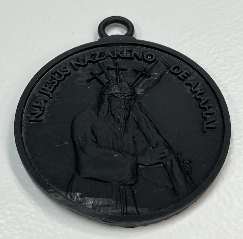
We tried PLA printing on the Bambu X1 using the Bambu Lab Slicer. We printed the design file a created during Week 2. To compare printing formats and materials we also tried it on the Saturn 4 which is brand new at our lab!
This is how it turned out on each one:
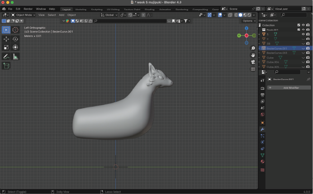
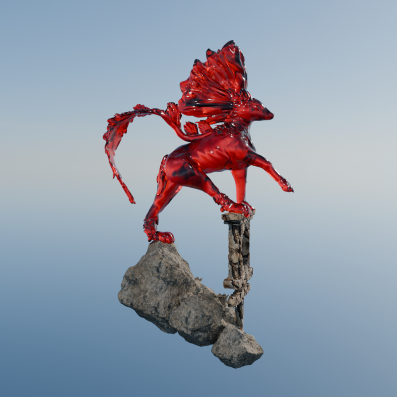
For the personal assigment I set out to sculpt a creature from scratch and print it in a translucent red resin from Anycubic.
I went with the same workflow as I described in Week 2, using Blender as my main tool and once it was done I used Chitubox to slice my object.
I normally start by hardmodelling a cube or a UV sphere and subdivided it so that I can have more polygons to stretch and bend towards the shape I want.
I also made some renders for this object:
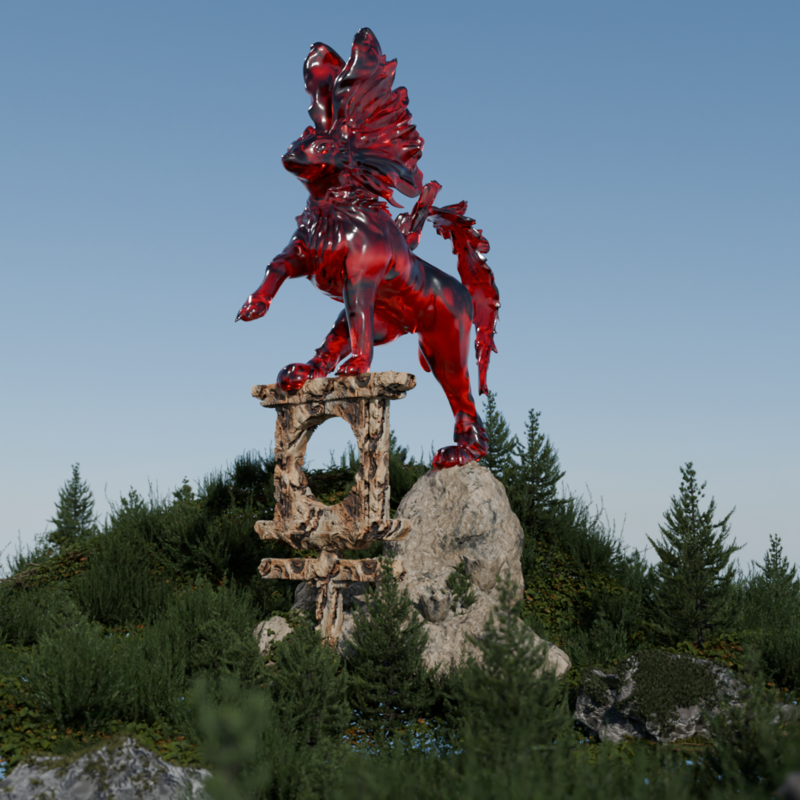
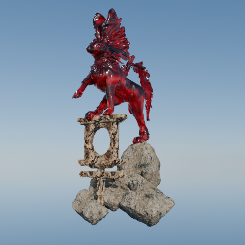
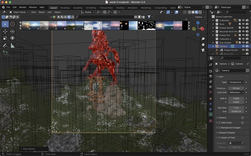
Btw, these are my rendering settings!

And this is how it looked in the viewport rendering:
I wanted this print to be about 16 cm wide, and the print volume* XYZ for our local SLA printer is 218 x 123 x 235 mm (8.6 x 4.8 x 9.3 inches). so I separated the body from the stand and imported as an .stl to Chitubox.
! You can follow this step-bystep guide to export a G-code using this slicing software. Also, this video covers important safety measures and post-use cleanup.
It was certainly a challenge to find the settings for my resin online so I studied some guidelines and tried the following parameters:
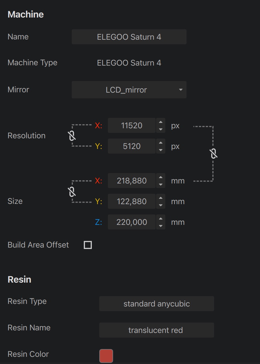
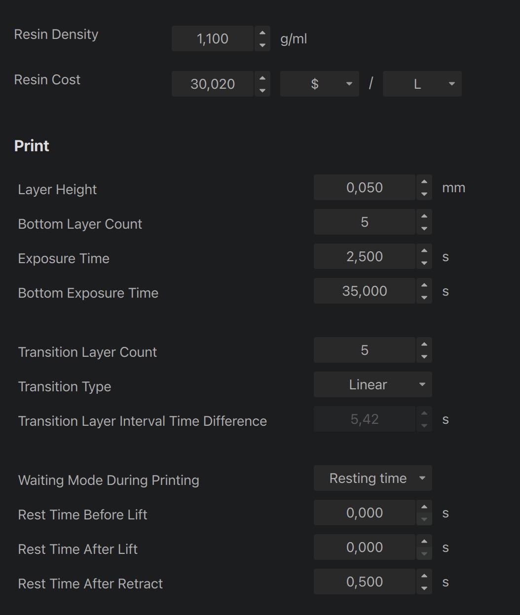
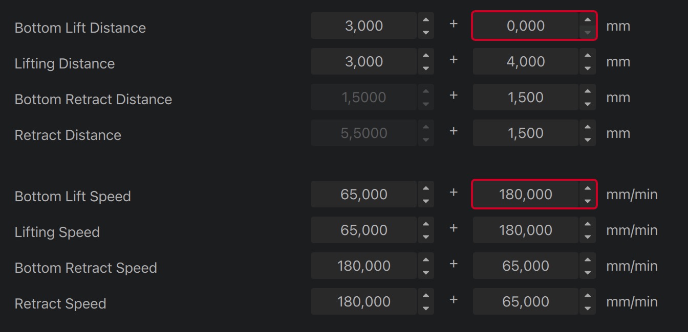
Then I conducted some print tests using the Photonsters Validation Matrix. You can find the datasheet for interpreting the results here. Luckily both of them worked as expected!
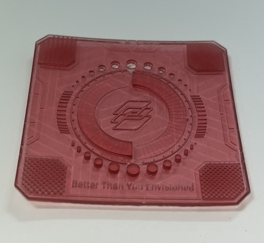
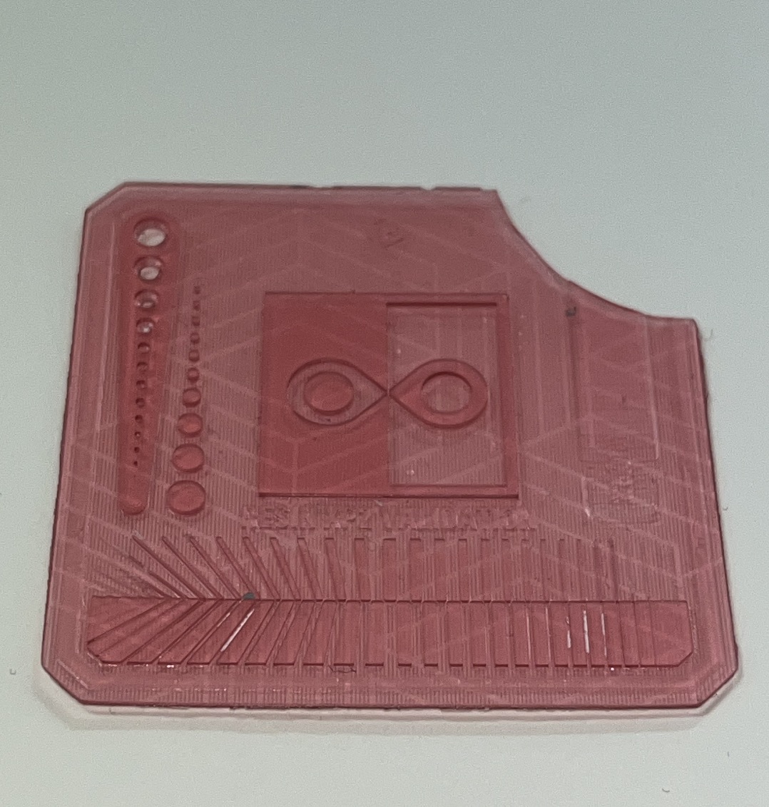
All set!
I called this little creature MUJIPUKI. And this is how it came out after the first batch of printing:
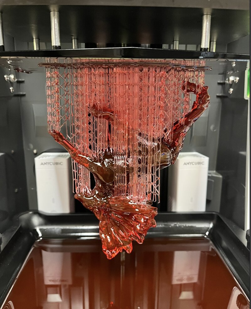
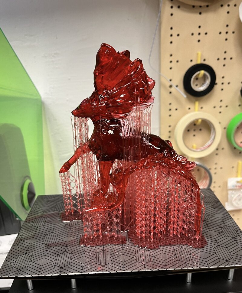
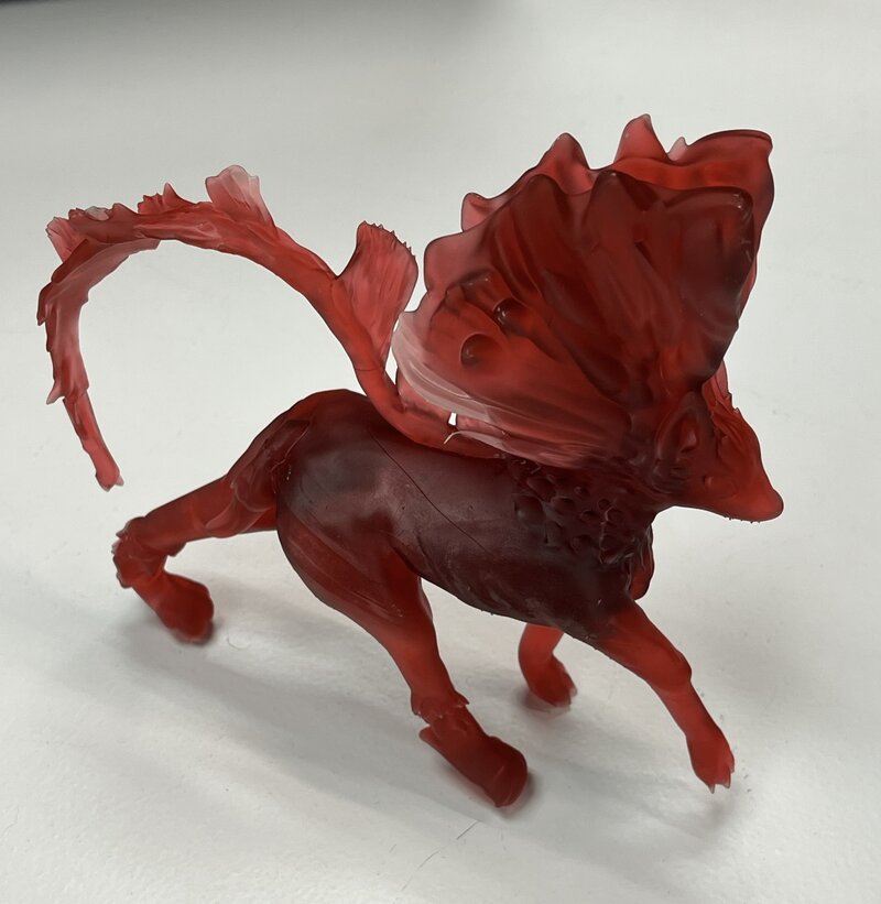
Pretty cool ain't it? I'm really happy with the result, I had been waiting quite a lot of time to try this printer model. And I'm loving every layer of it! Thank you for catching up with this week's content.
Follow up to see what I create next week ;)
xoxoxo
p.s. You can access my renders and design files here.