Week 11
This week at Fab Academy, we dived into how to connect multiple microcontrollers so they can work together. Either through wired or wireless networks. This is a key step in designing more complex, distributed, and modular systems.
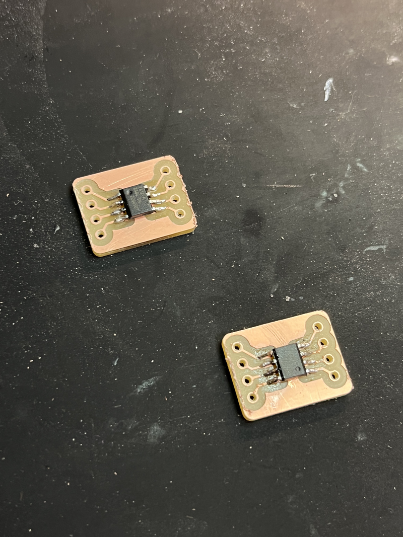
Let's make an Attiny412 have a friend to talk to.
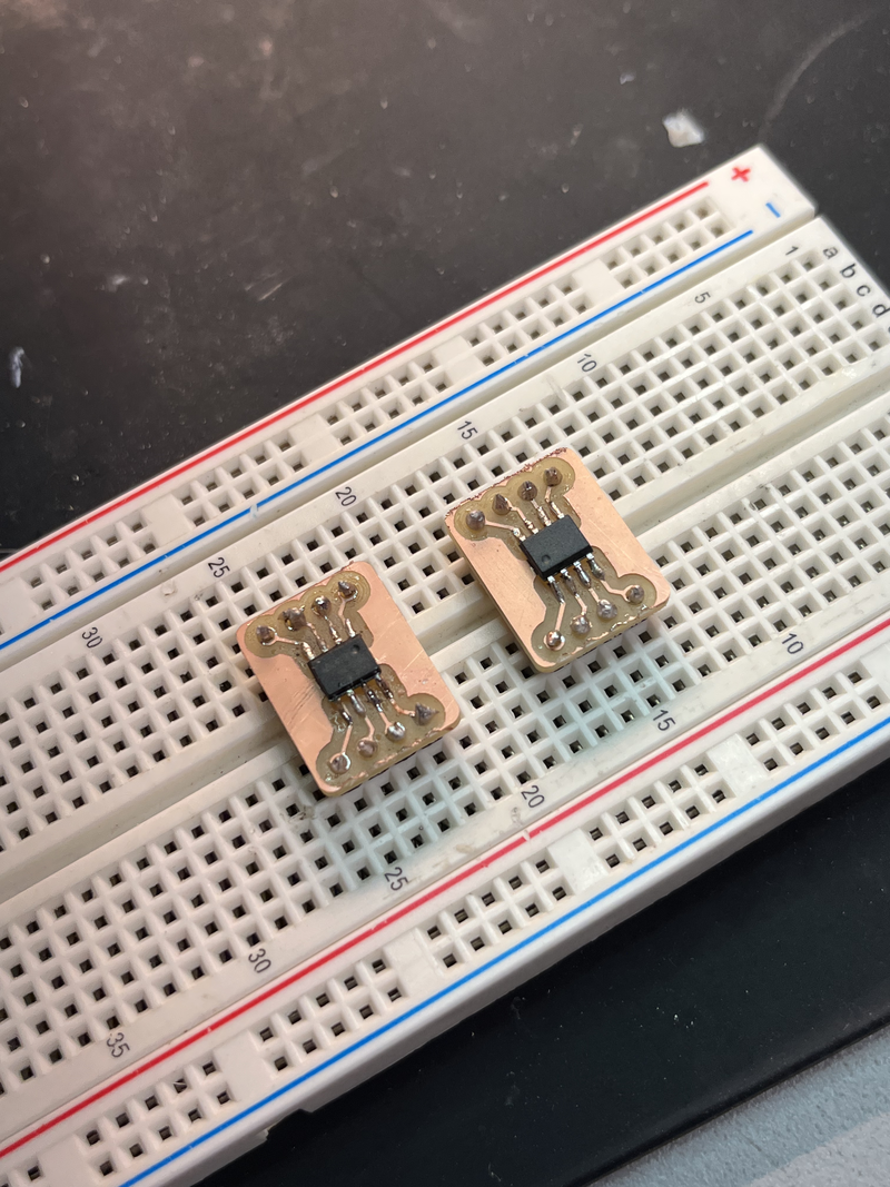
Since it's tiny I created a board to surface-mount it and place it over the breadboard:
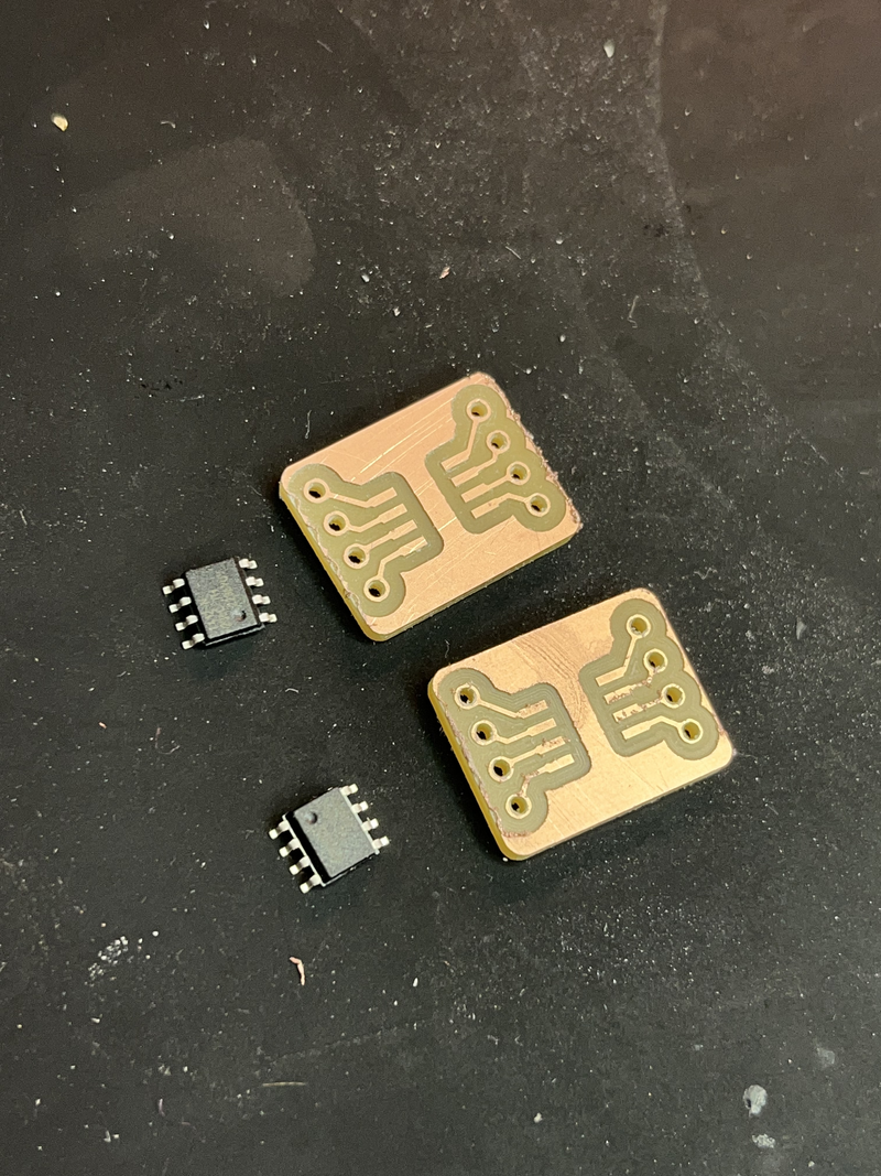
Because I knew this was not going to be easy, the goal was to freely try the connections without the compromise of re-doing a full board.
The idea is simple; connect two Attiny412 via I2C, one would be the master who would tell the other, the slave.
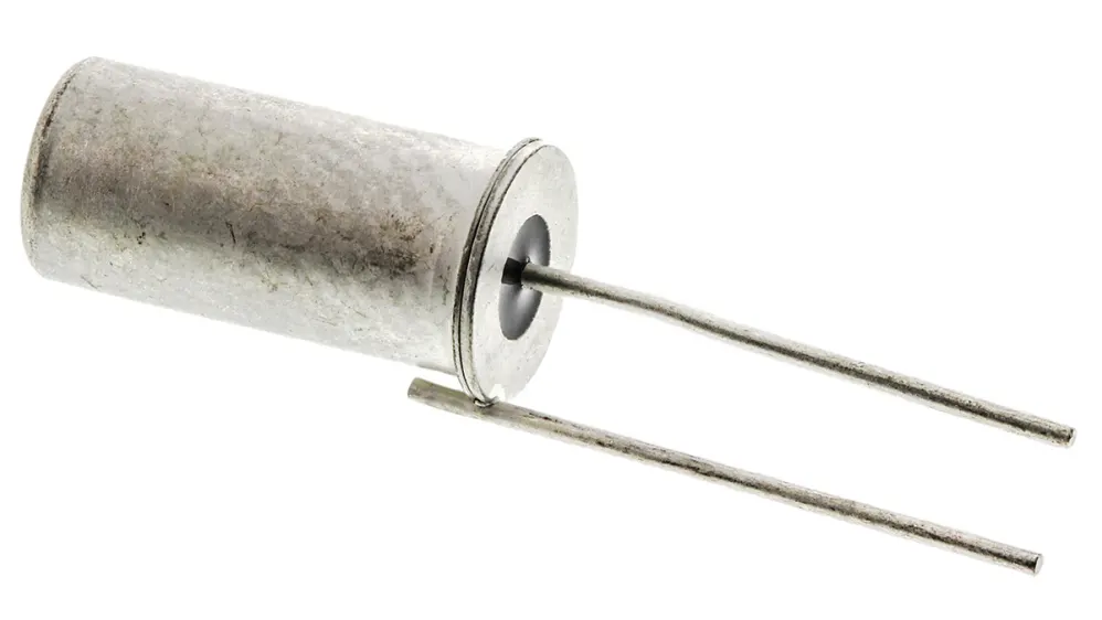
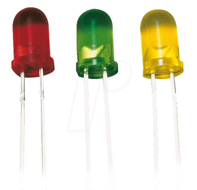
Master would have a tilt switch and some leds.
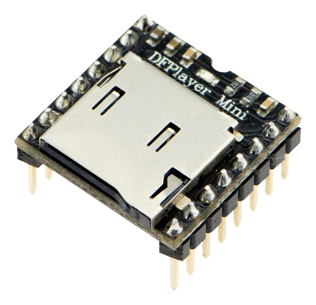
The slave on the other hand, would be wired to a DFPlayer Mini, which I had tried during last week.
When not tilted ---> DFPlayer Mini plays song until done.
When tilted -------> DFPlayer would stops and the leds turn on.
So before going deep into I2C, I thougth it would be better to try the connection of the components within one board. And since Attiny412 doesn't have UART communication, for the purpose of possible debugging, I tried the code in the Barduino.
With ChatGPT's help we got it working.
#include <SoftwareSerial.h>
#include <DFRobotDFPlayerMini.h>

#define TILT_PIN 3      // Tilt switch is connected to PA3 (pin 3)
#define LED_PIN 7       // LED is connected to PA7 (pin 7)
#define DFPLAYER_RX 1   // DFPlayer TX goes to this pin (PA1)
#define DFPLAYER_TX 2   // DFPlayer RX goes to this pin (PA2)

SoftwareSerial dfSerial(DFPLAYER_RX, DFPLAYER_TX);  // RX, TX for software serial
DFRobotDFPlayerMini dfplayer;

bool playing = false;   // Keeps track of whether audio is currently playing

void setup() {
  pinMode(TILT_PIN, INPUT_PULLUP);  // Set tilt pin as input with internal pull-up resistor
  pinMode(LED_PIN, OUTPUT);         // Set LED pin as output

  dfSerial.begin(9600);             // Start SoftwareSerial at 9600 baud
  if (!dfplayer.begin(dfSerial)) {  // Try to connect to DFPlayer
    // If connection fails, stop here (optional)
    while (true);
  }

  dfplayer.volume(20); // Set initial volume (0 to 30)
}

void loop() {
  bool tilted = digitalRead(TILT_PIN) == LOW;  // Check if tilt switch is tilted

  if (tilted && !playing) {
    digitalWrite(LED_PIN, LOW);    // Turn off LED
    dfplayer.play(1);              // Start playing track 001.mp3
    playing = true;                // Remember that it's playing
  }
  else if (!tilted && playing) {
    digitalWrite(LED_PIN, HIGH);   // Turn on LED
    dfplayer.stop();               // Stop playback
    playing = false;               // Remember that it's not playing
  }

  delay(200);  // Wait a bit to avoid spamming the DFPlayer or reacting to noise
}
-
Uses a tilt switch on pin PA3
-
Turns an LED on/off on PA7 based on the tilt state
-
Plays or stops audio using a DFPlayer Mini
-
Connects the DFPlayer via SoftwareSerial on PA1 (RX) and PA2 (TX)
-
Makes sure the audio only plays once per tilt and stops if tilt returns"
Understanding the code
I tried to understand the code from scratch to truly internalize it.
First I declare the variables.
Then this part was a little confusing.
DFRobotDFPlayerMini dfplayer;
Aparently, this line creates an object named dfplayer from the DFRobotDFPlayerMini class.
Other examples of "SomeLibraryClass nameYouChoose;" that you might recognize:
SoftwareSerial mySerial;
Adafruit_NeoPixel strip;
Servo myServo;
dfplayer.begin(...) is a function.
That means it requires some input (called "arguments") in parentheses, just like when you write:
Serial.begin(9600);
It's telling Serial what speed to use. So, for the DFPlayer:
dfplayer.begin(dfSerial);
This is telling the DFPlayer object: "Start using this Serial connection to talk to the actual DFPlayer module."
Why dfSerial? Earlier in the code (or at least in most DFPlayer setups), you create a serial connection like this:
SoftwareSerial dfSerial(0, 1); // Or whatever pins you're using
So dfSerial is the software serial connection between your microcontroller (Attiny or Barduino) and the DFPlayer board. That’s how they talk.
When the library function .begin() runs, it needs to know what connection to use, so we give it dfSerial.
Functions use parentheses to take input arguments.
dfplayer.begin(...) expects a serial connection as input.
You pass it dfSerial, because that’s the connection you made to the DFPlayer.
while (true);
is an infinite loop that does nothing. It’s a clean way to halt a program if something goes wrong, like a hardware failure. It's the same as writing while (true){}
bool playing = false;
I'm creating a variable named playing that will keep track of whether music is currently playing. Right now, I’m saying it’s not playing. It's a flag that can be fliped later in the code and I can use it to decide when to start or stop the DFPlayer.
It helps prevent triggering the same action over and over again when the switch doesn’t change.
Hey! I didn't show you how it worked! Look ;)
Two Attiny412 Blinking At Each Other
For the purpose of this program's schedule, I’ve decided to keep things simple: I'll just connect two Attiny(s) and leave the DFPlayer and tilt switch for another time.
Simplicity is part of the learning process. Especially when you're working under tight deadlines... hehe.
After a lot of effort and debugging, we finally got the master to successfully command the slave to blink an LED.
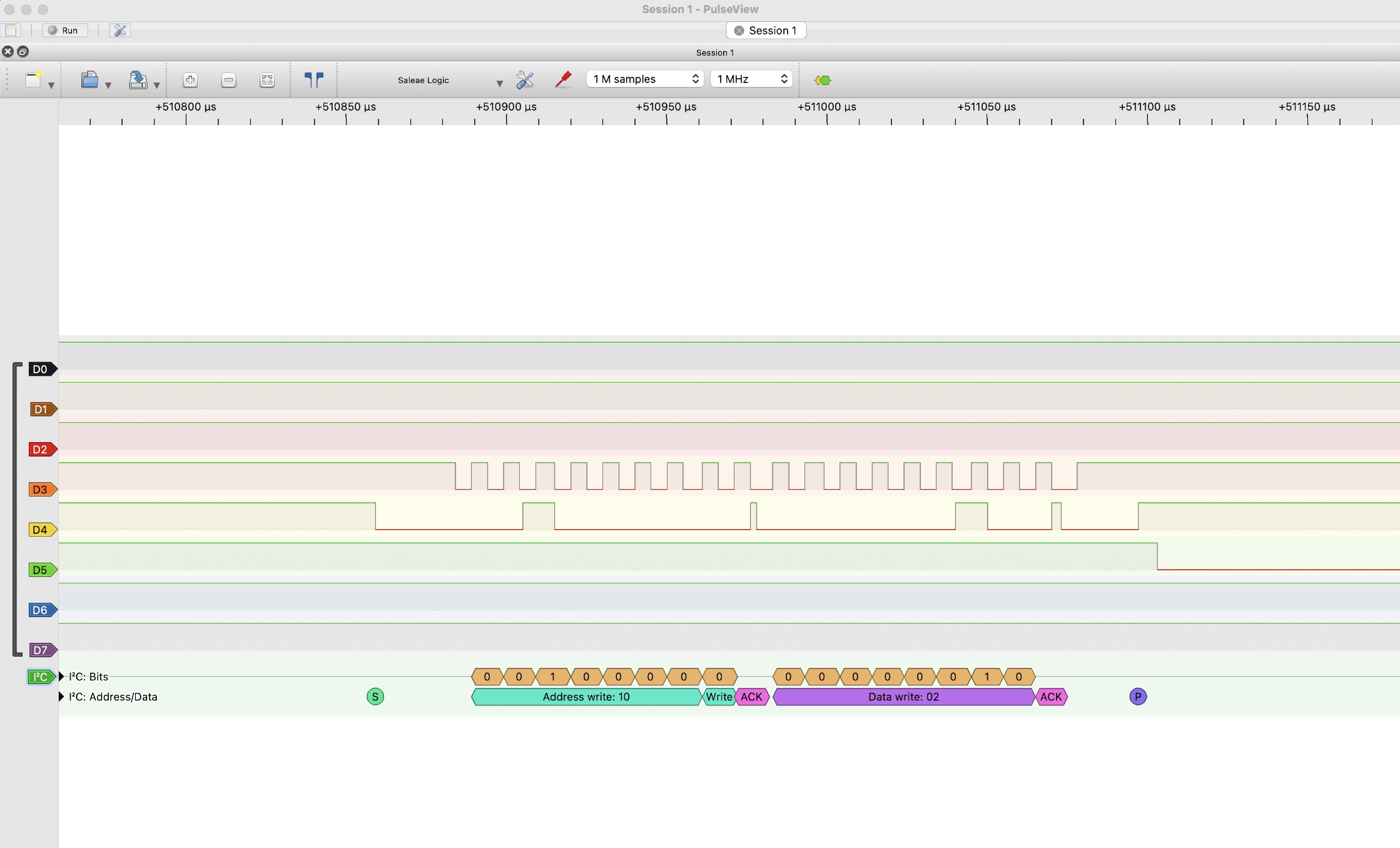
I lost quite a bit of time because I didn’t realize that the SDA and SCL lines needed pull-up resistors (10kΩ). We tried everything, checking solder joints with a multimeter, inspecting signals on the oscilloscope, and even using a logic analyzer that showed the following readings of the SDA and SCL while ON.
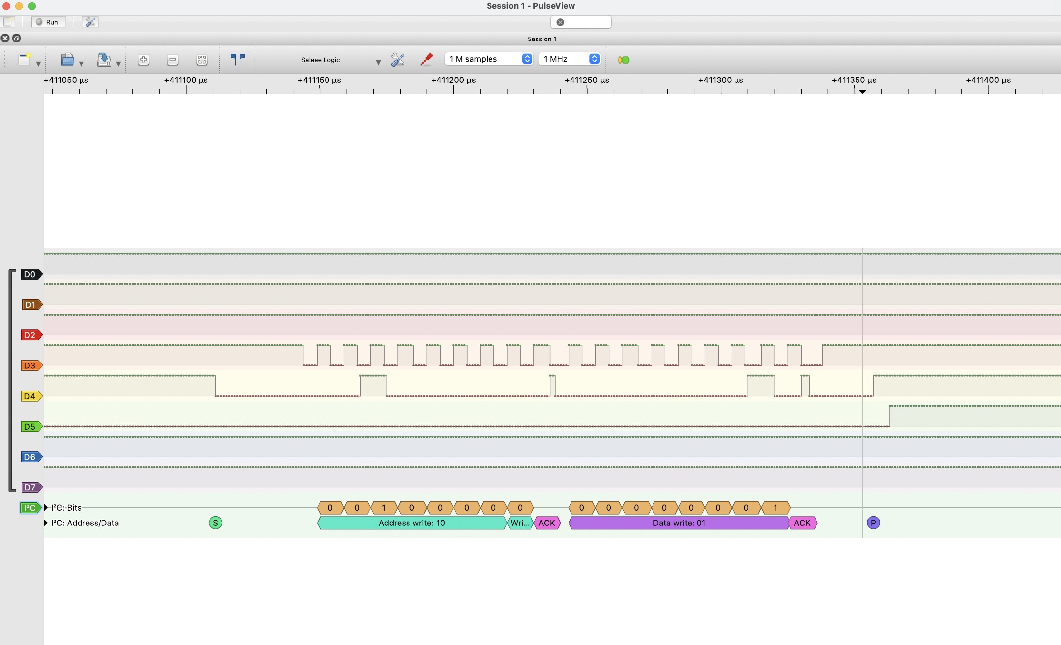
And this was OFF:
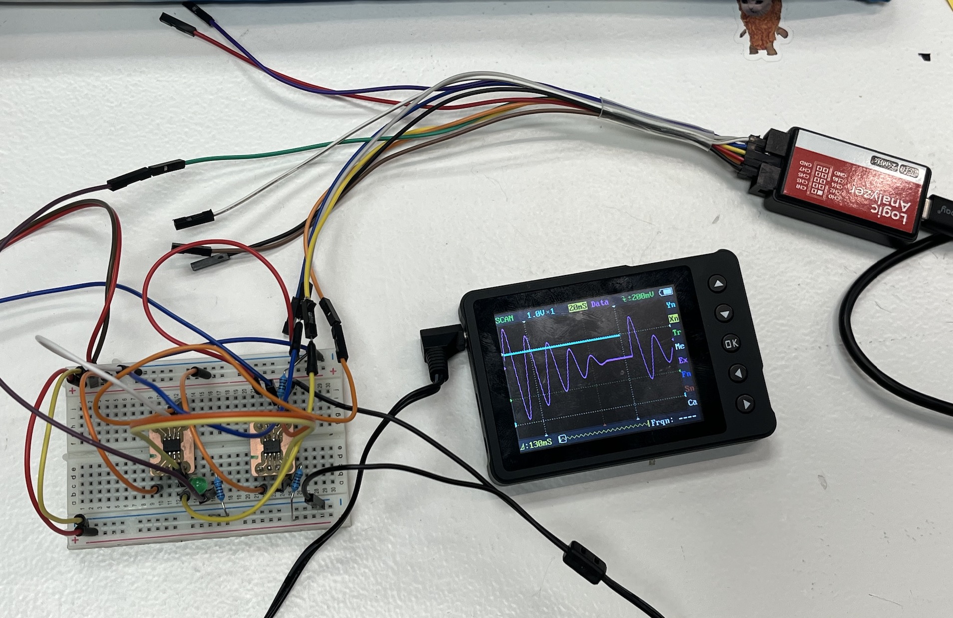
The whole setup:
But once we figured that out and uploaded this code to the master.
#include

void setup() {
  Wire.begin();
  delay(1000);

  // Step 1: Send 0xAA to prepare slave
  Wire.beginTransmission(0x10);
  Wire.write(0xAA);
  Wire.endTransmission();
  delay(10);

}

void loop() {
  // Nothing here
  // Step 2: Send 0x01 to turn on LED
  Wire.beginTransmission(0x10);
  Wire.write(0x01);
  Wire.endTransmission();

  delay(100);


    // Nothing here
  // Step 2: Send 0x01 to turn on LED
  Wire.beginTransmission(0x10);
  Wire.write(0x02);
  Wire.endTransmission();

  delay(100);
}
And this code to the slave.
#include

const int ledPin = 1;  // LED pin, make sure to connect an LED here for debugging

void setup() {
  Wire.begin(0x10);  // Set slave address to 0x10
  Wire.onReceive(receiveEvent);  // Register the event handler for I2C receive

  pinMode(ledPin, OUTPUT);  // Set LED pin as output
}

void loop() {

  // Nothing needed here, we just handle I2C data in the background
}

void receiveEvent(int numBytes) {

  while (Wire.available()) {
    byte command = Wire.read();  // Read the received byte

    if (command == 0x01) {
      // Turn on the LED for debugging
      digitalWrite(ledPin, HIGH);
    } else {
      // If another command is received, turn off the LED
      digitalWrite(ledPin, LOW);
    }
  }
}
It finally worked!
Yipiii. May not be rocket science, but I've learned A LOT during the process and now I can confidently use the oscilloscope and the rest of the components I've experimented with. I also feel very comfortable with the Attiny412 and incorporating it into the rest of my projects. But for the moment, I'll leave them to rest and chat about their toxic master/slave relationship.
Let's give them space.
See you next week.