Week 15
...and on this week: Integrating a functioning system!
This is the moment when mechanical parts, electronic boards, sensors, outputs, software and more come together to form a cohesive, working system.
We'll be engineering orchestration. Follow me! ദ്ദി(˵ •̀ ᴗ - ˵ ) ✧
What is key?
Integration is about ensuring every component communicates effectively, operates reliably, and contributes to a unified, purposeful function.
It requires both a high-level architectural vision and attention to detail at every interface point.
We'll be taking a closer look at my final project break it down into its core components and development stages.
Architecture Overview
An architecture overview is a high-level map of your system. It shows how the different components such as hardware, software, and mechanical, connect and interact.
This includes microcontrollers, sensors, power systems, communication paths, and interfaces, helping others understand the overall design logic of your project.
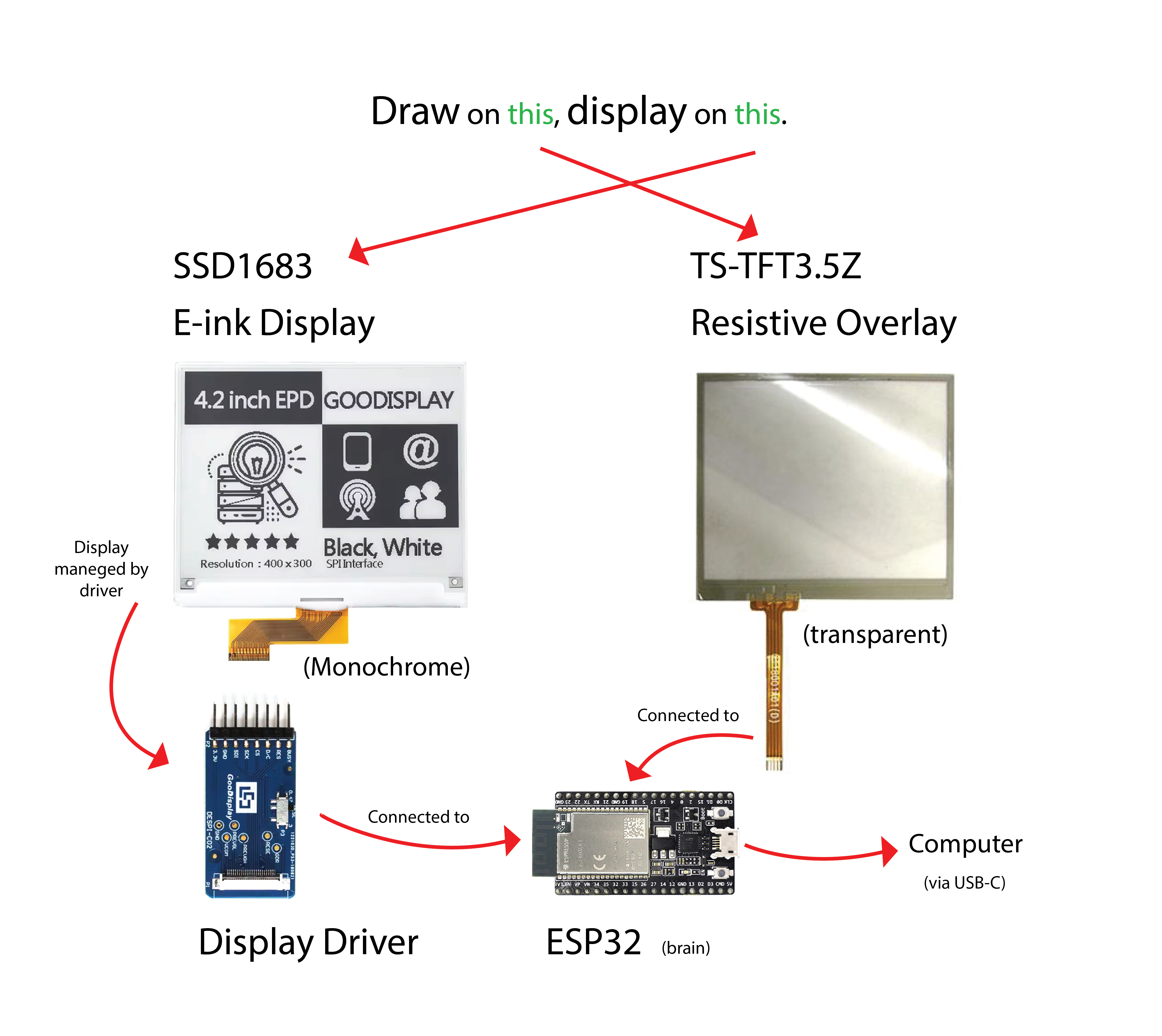
In my case, I am including a resistive touchscreen where I will get readings that will be screened in a E-ink display. The display has its own driver* a facilitator for components to communicate to make it more "arduino friendly". Both the display and the touchscreen overlay will be controlled by a ESP32 which has a USB-C port for programming and communicating with a computer.
Communication Between Components
For my final project, the E-Ink display communicates with the ESP32 using the SPI protocol, which is ideal for high-speed data transfer required by graphic updates.
In contrast, the resistive touchscreen overlay operates with a 4-wire analog interface (X1, X2, Y1, Y2). Instead of using a digital protocol like I2C or SPI, I’ll read raw analog values from these pins using the ESP32’s built-in ADCs to detect touch position through voltage division.
The ESP32 serves as the central hub, managing both user input and visual feedback.
User Interface
What do I mean by raw analog values? So to handle user input, I will use a 4-wire resistive touchscreen and read it with ADC pins.
I initially explored libraries like ESP32TouchScreen for easier calibration and integration, but most were tightly coupled with specific TFT displays. So I implemented a simple manual reading method:
void setup() {
    Serial.begin(9600);  // Open serial communication
}

void loop() {
    // Read Y coordinate
    pinMode(A0, INPUT);
    pinMode(A1, INPUT);
    digitalWrite(A0, LOW);
    pinMode(A3, OUTPUT);
    digitalWrite(A3, HIGH);
    pinMode(A2, OUTPUT);
    digitalWrite(A2, LOW);
    int y = analogRead(A1);

    // Read X coordinate
    pinMode(A2, INPUT);
    pinMode(A3, INPUT);
    digitalWrite(A2, LOW);
    pinMode(A1, OUTPUT);
    digitalWrite(A1, HIGH);
    pinMode(A0, OUTPUT);
    digitalWrite(A0, LOW);
    int x = analogRead(A3);

    // Send the coordinates over Serial
    Serial.print(x);
    Serial.print(",");
    Serial.println(y);

    delay(700); // Smooth drawing
}
Power Management Strategy
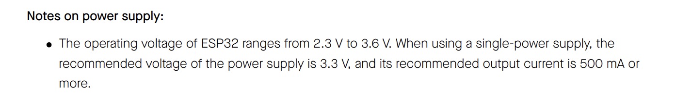
The main board, ESP32 can handle a power range between 2.3V and 3.6V if you check its datasheet.
On the other hand, the GDEY042T81 E-Ink display operates at a voltage of 3.3V, making it fully compatible with microcontrollers like the ESP32.
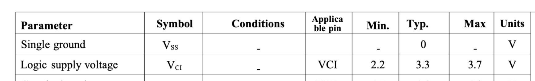
This means you can safely drive it with 3.3V, such as from the ESP32, provided the ADC reference matches.
And finally, the TSTFT3.5Z touchscreen does not explicitly specify an operating voltage for the touch panel itself because, typically, 4-wire resistive touchscreens do not require a fixed "supply voltage" in the same way as active digital components. Instead, the touchscreen is interfaced by applying voltage across the X or Y layers (usually 3.3V or 5V, depending on your controller), and then reading analog values via ADC pins.
Enclosure Design
The project enclosure is designed as a booklet-style device, with the touchscreen on one side and the E-Ink display on the other, connected by a hinge mechanism.
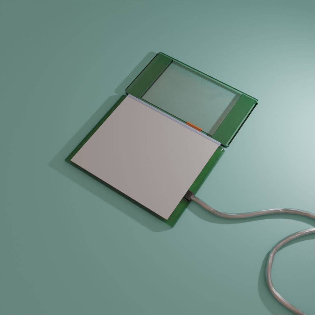
To maintain the transparency of the touchscreen, the PCB will be mounted behind the E-Ink display.
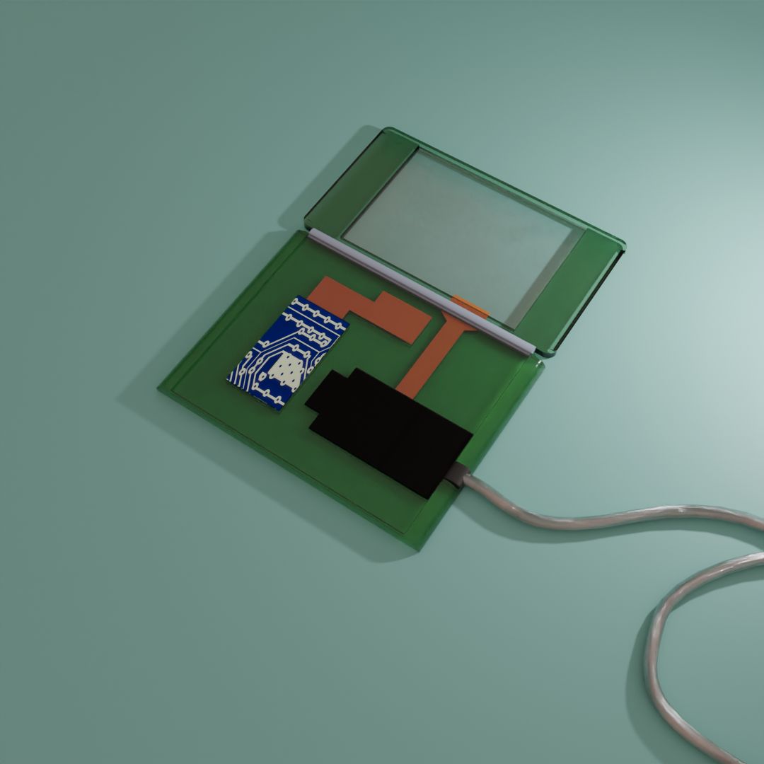
The most significant design challenge lies in ensuring that the flexible PCB connections from the touchscreen remain secure and undamaged as the hinge rotates.