Week 3
This week, we moved from digital design to physical fabrication using laser cutters and vinyl cutters. I explored different materials, learned how to prepare files for cutting, and experimented with parametric design to create a press-fit construction kit.
In this week, I had the opportunity to collaborate with my classmates to test the workflow of computer-controlled cutting. We conducted experiments to characterize our laser cutter's focus, power, speed, kerf, and joint clearance.
You can read more about our group's findings here: Group Assignment - Week 3
Laser Cutting: How It Works
A laser cutter is a CNCComputer Numerical Control* machine that uses a high-powered laser to cut or engrave materials. It follows a vector path (usually from an SVG or DXF file) to precisely cut through wood, acrylic, cardboard, and more.
My Workflow for Laser Cutting:
- Designing the File: I used Adobe Illustrator to create vector-based designs.
- Choosing the Right Material: I tested cardboard for my press-fit kit.
- Adjusting Settings: I had to tweak speed, power, and frequency to get clean cuts.
- Accounting for Kerf: Laser burns material, so I needed to compensate for kerf width.
- Test Cuts & Final Assembly: After testing, I adjusted the design and cut my final pieces.
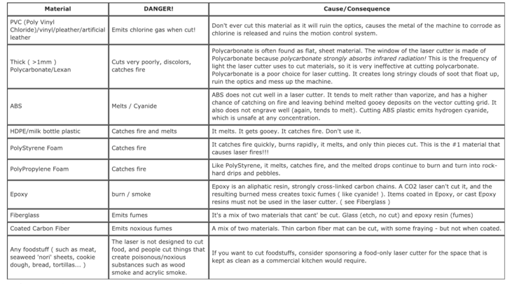
Material Selection:
Choose materials that are safe for laser cutting, like acrylic, wood, cardboard, and leather. Avoid flammable or toxic materials like PVC.
this are ok c;
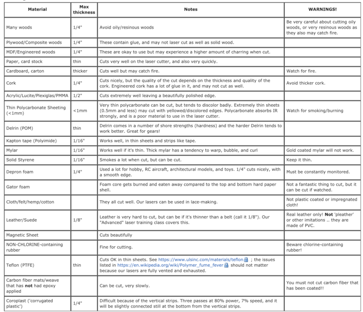
this are not ok
Parameters:
Adjust these settings to control the cut:
- Speed: How fast the laser moves.
- Power: Laser intensity.
- Frequency: Pulse rate for cutting or engraving.
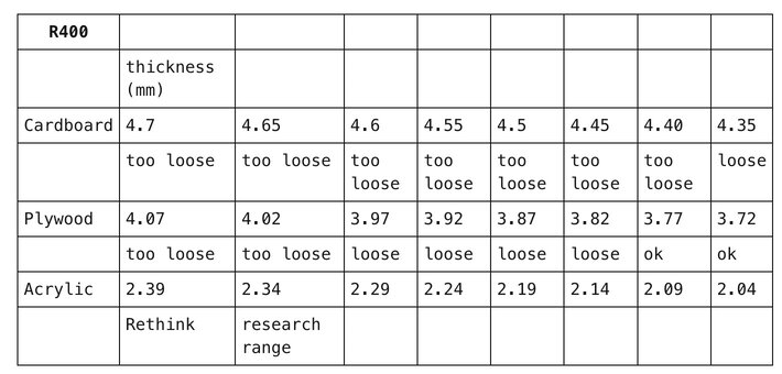
Laser Cutter Test Results with R400
We worked with the R400 LaserJet and tested materials such as cardboard, plywood, and acrylic at varying thicknesses. Below are the results of our tests:
Safety Precautions:
- Wear safety goggles to protect your eyes.
- Ventilate the workspace to avoid harmful fumes.
- Monitor the machine at all times.
Kerf & Parametric Design
When the laser cuts a material, it removes a small amount—this is called the kerf. If you don’t account for kerf, your pieces may not fit together properly.
Kerf Testing
In our group assignment, we conducted tests to determine the kerf for various materials. We designed a comb-like structure with slots decreasing in width by 0.05 mm increments. By cutting this design and testing the fit of each slot, we identified the optimal slot width for a snug fit. The kerf was then calculated as the difference between the material's thickness and this optimal slot width.
For example, with 4.7 mm thick cardboard, we found that a slot width of 4.35 mm provided a snug fit, indicating a kerf of 0.35 mm. This method allowed us to determine precise kerf values for different materials, ensuring better accuracy in our designs.
Parametric Design
To streamline the process and avoid manually adjusting for kerf every time, I created a parametric design in Blender using Geometry Nodes. This allowed me to easily modify the design based on material thickness, making it adaptable to different materials.
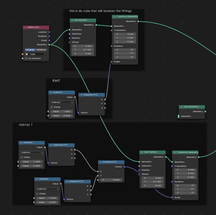
Geometry Nodes in Blender is a powerful system for creating and manipulating 3D geometry using a node-based interface. Instead of modeling manually, you connect various nodes to perform actions like transforming shapes, adding effects, and modifying geometry in a procedural, non-destructive way.
Press-Fit Construction Kit
For my individual assignment, I designed a press-fit construction kit. This type of kit consists of interlocking pieces that fit together without glue or fasteners.
✔ Software Used: Blender + Illustrator ✔ Material: 3mm Cardboard ✔ Key Challenge: Making a modular design and apply geometry nodes to modify the fittings according to each material ✔ Final Design: ~in process~ after some trials and errors
How It Started
I began by designing a leaf-inspired structure in Adobe Illustrator using the Pen Tool to create smooth curves.
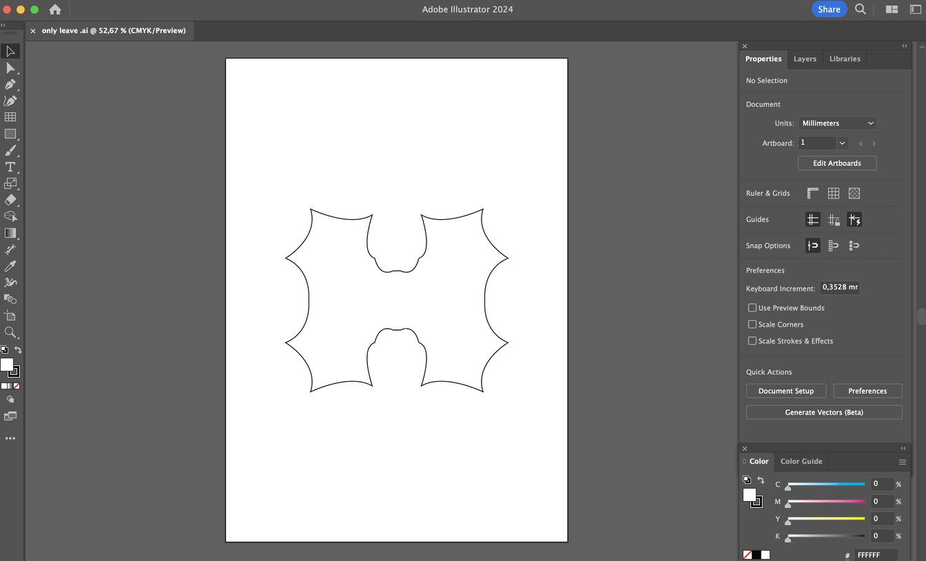
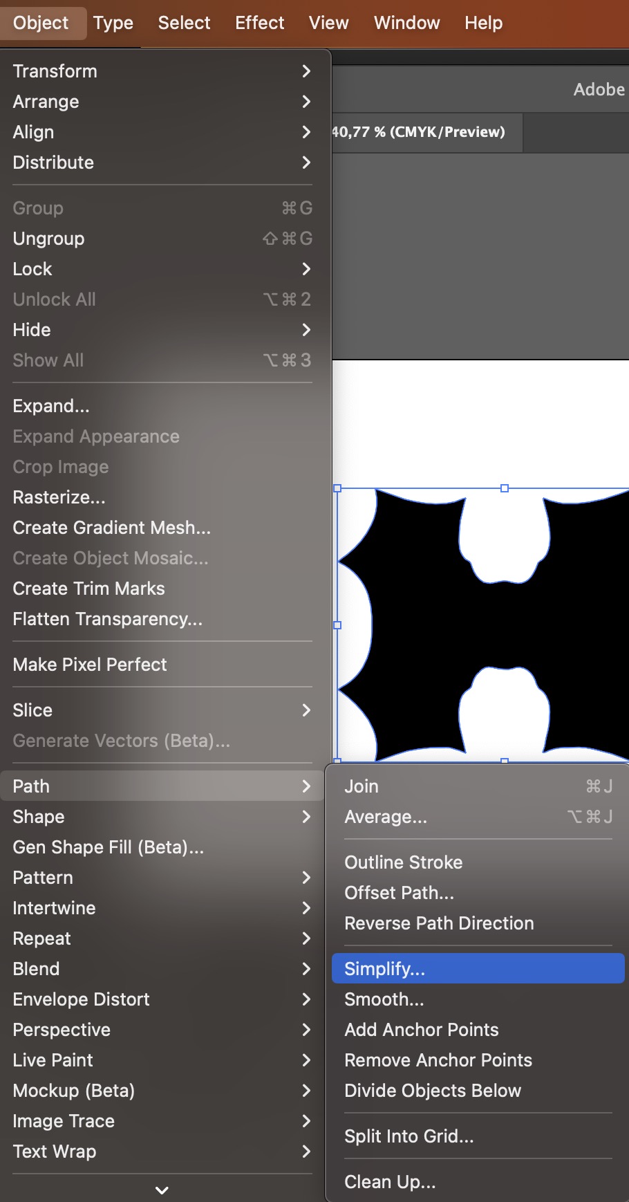
After completing the design, I made sure to fill the shape and simplify the anchor points to avoid topology issues when importing it into Blender.
Once ready, I exported the file as a .svg. and imported it into Blender.
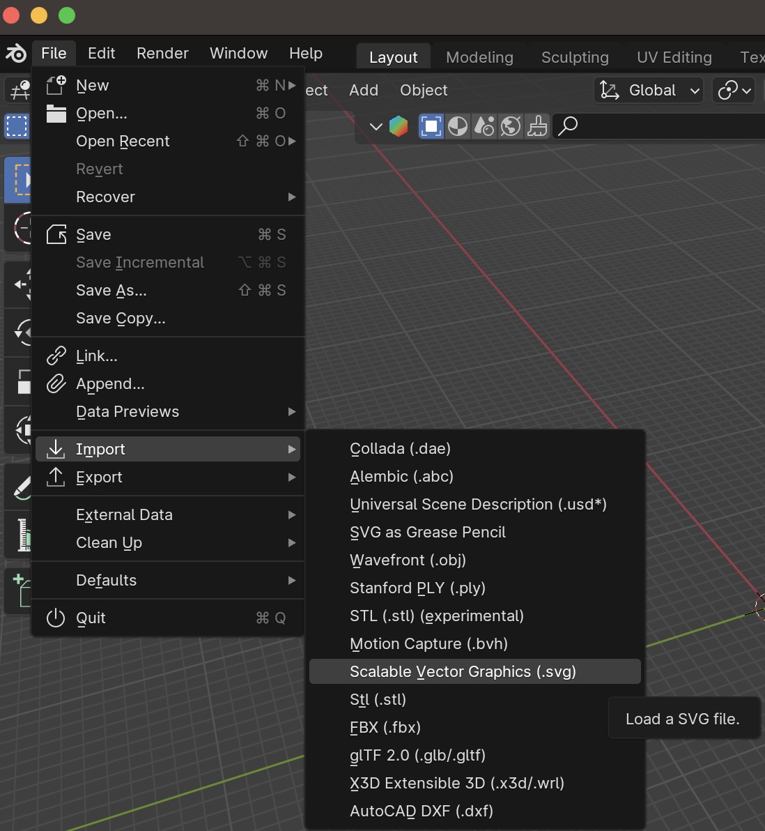
This will load the design as a curve.
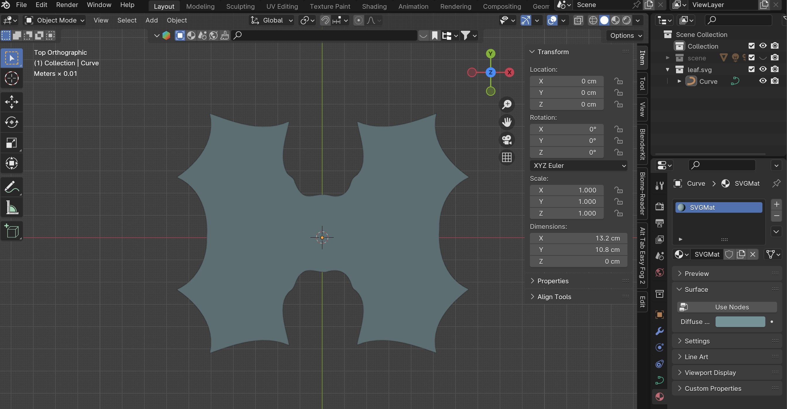
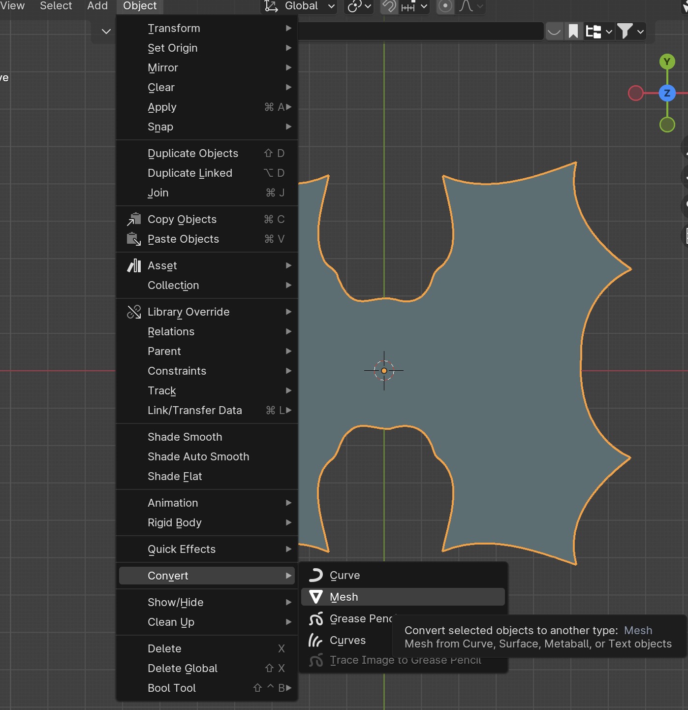
For the operations I am about to perform, it is necessary to convert it into a mesh like this:
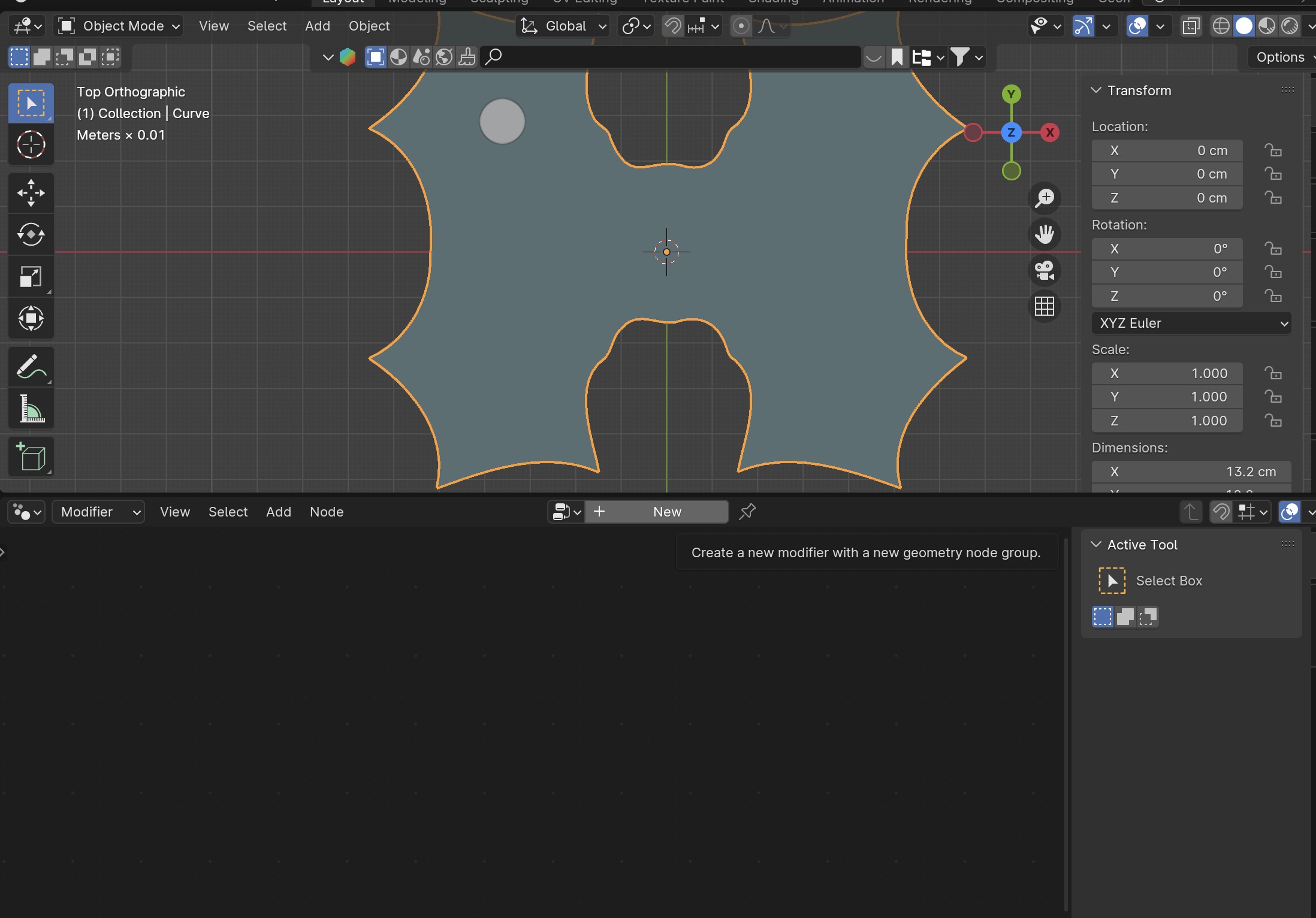
I parted my viewport into two sections for better vision; on the top is the 3DViewport and on the bottom the Geometry Node Editor. Then I clicked on New while having my shape selected.
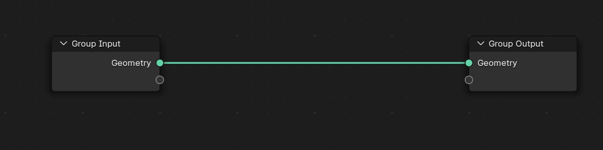
Generating a new geometry input and output.
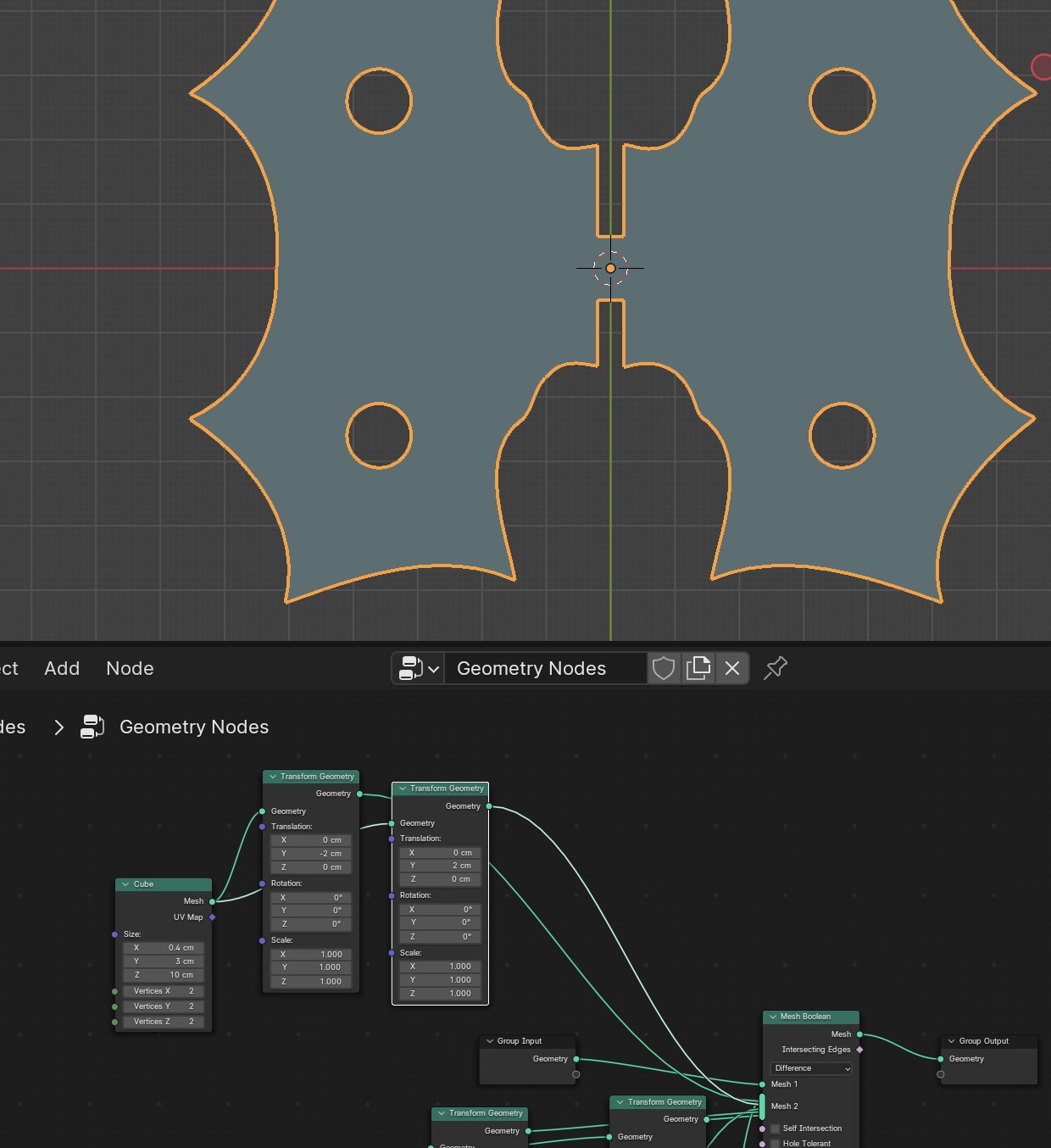
I took note from this tutorial and added a cylinder shape and a mesh boolean node by pressing Shift A and typing the nodes' name.
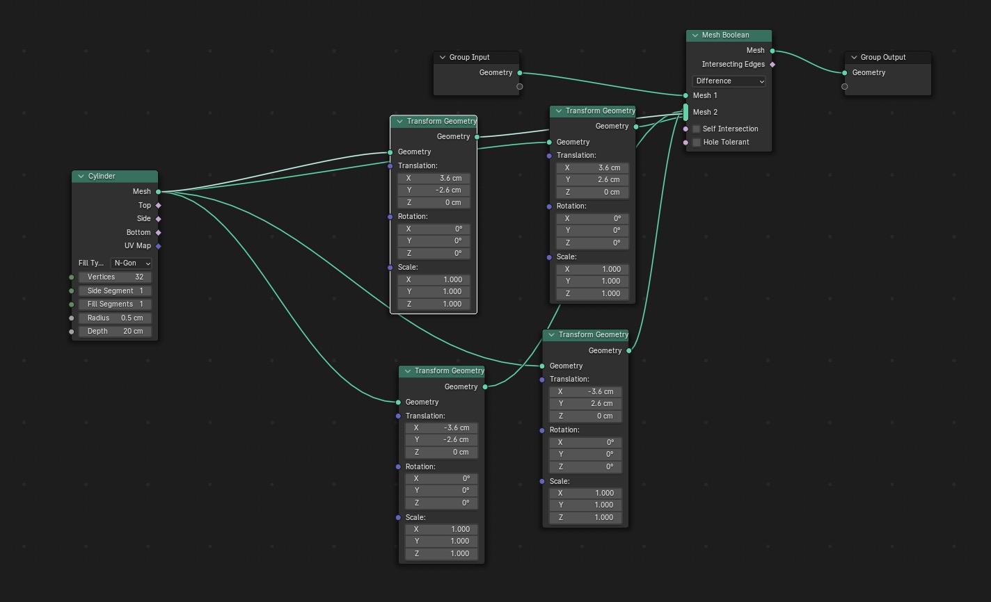
I also included the transform node to add 3 more cylinders with different locations. Here you can see how I modify the radius parameter:
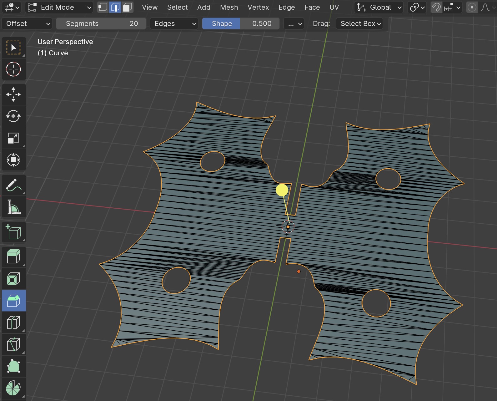
Then, I added a cube (2) in the same way I added the cylinders. These would be booleaned where the press-fit joins. By adjusting the cube’s scale using parameters, I can compensate for kerf—the slight material loss during the laser cutting process.
With the shape looking like this:
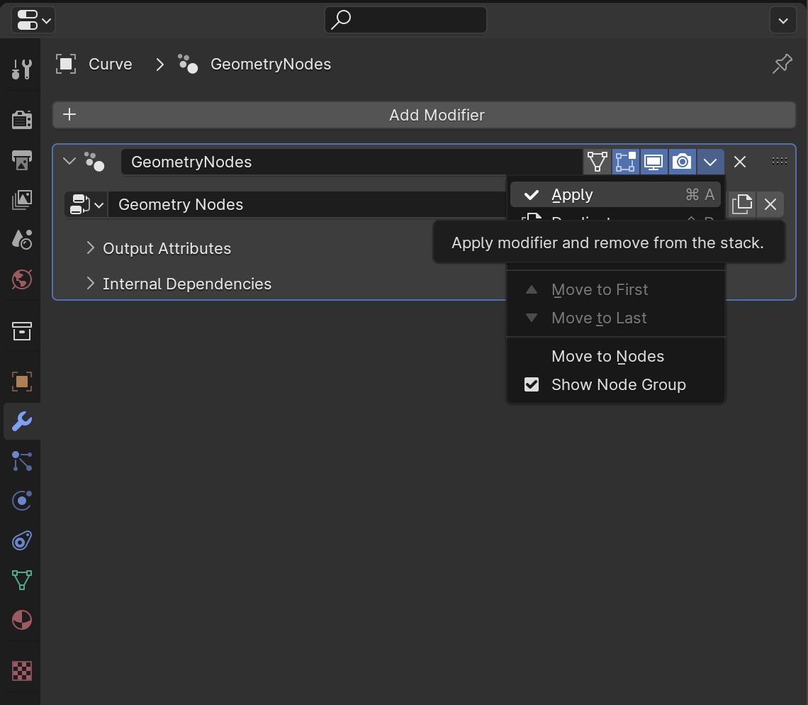
I applied the Geomtry Nodes Modifier.
Stepped into edit mode and selected the outlines of my shape. A helpful tip for this is to hold the Option (⌥) (Alt for Windows) key while clicking on a vertex or edge that makes the outline loop.
With it selected press Command (⌘) + D and Z to duplicate the shape and move it up. Now, the same way it was converted to a mesh, convert it into a curve.
Go to the Blender Preferences and install the following add-on that will allow us to export it as a .dxf file.
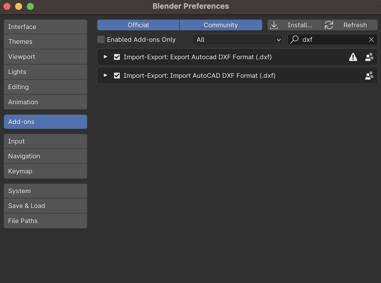
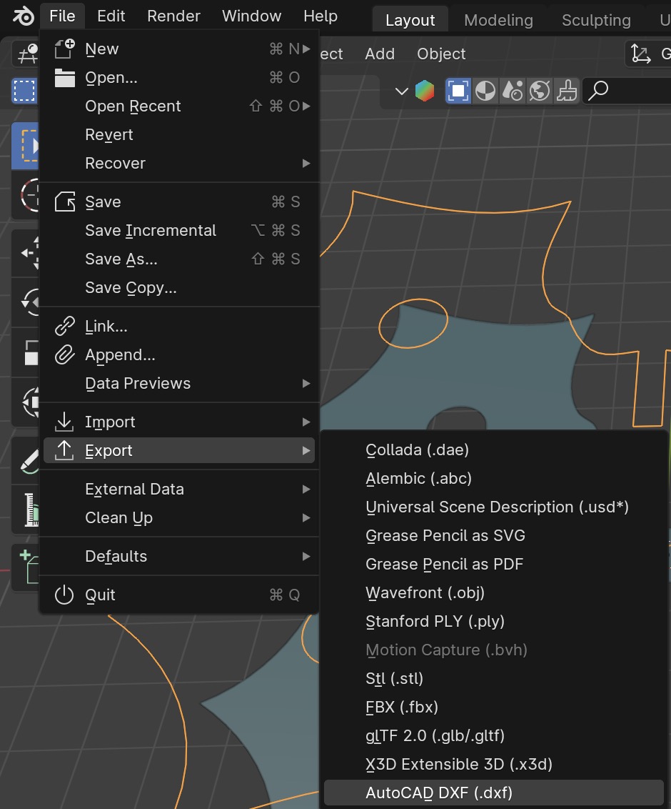
Once you tick on your add-ons you will see it as an export option.
Just to make sure it was working I went ahead and imported it as a .dxf in Illustrator.
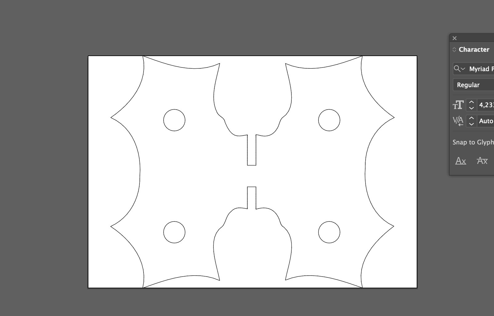
Awesome!
Access the Blender file here
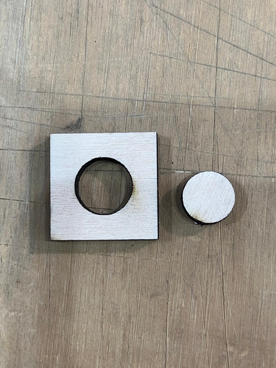
I laser cut it in cardboard:
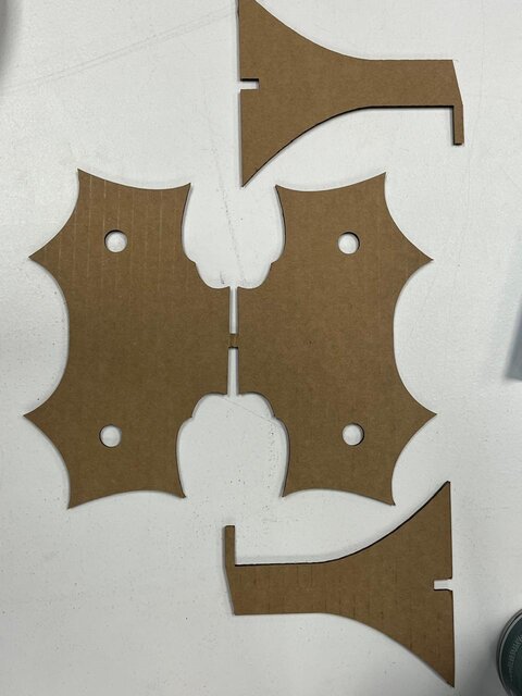
However, I wasn’t satisfied with the outcome. Neither the result itself nor the overall experience using the laser cutter. To improve my understanding of the process, I decided to create a new design.
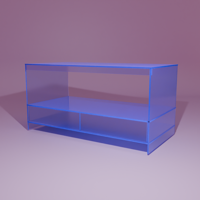
My goal was to build a small rack:
I planned to 3D print the connectors that would hold the pieces together, so I created the layout in Illustrator with appropriately placed holes:
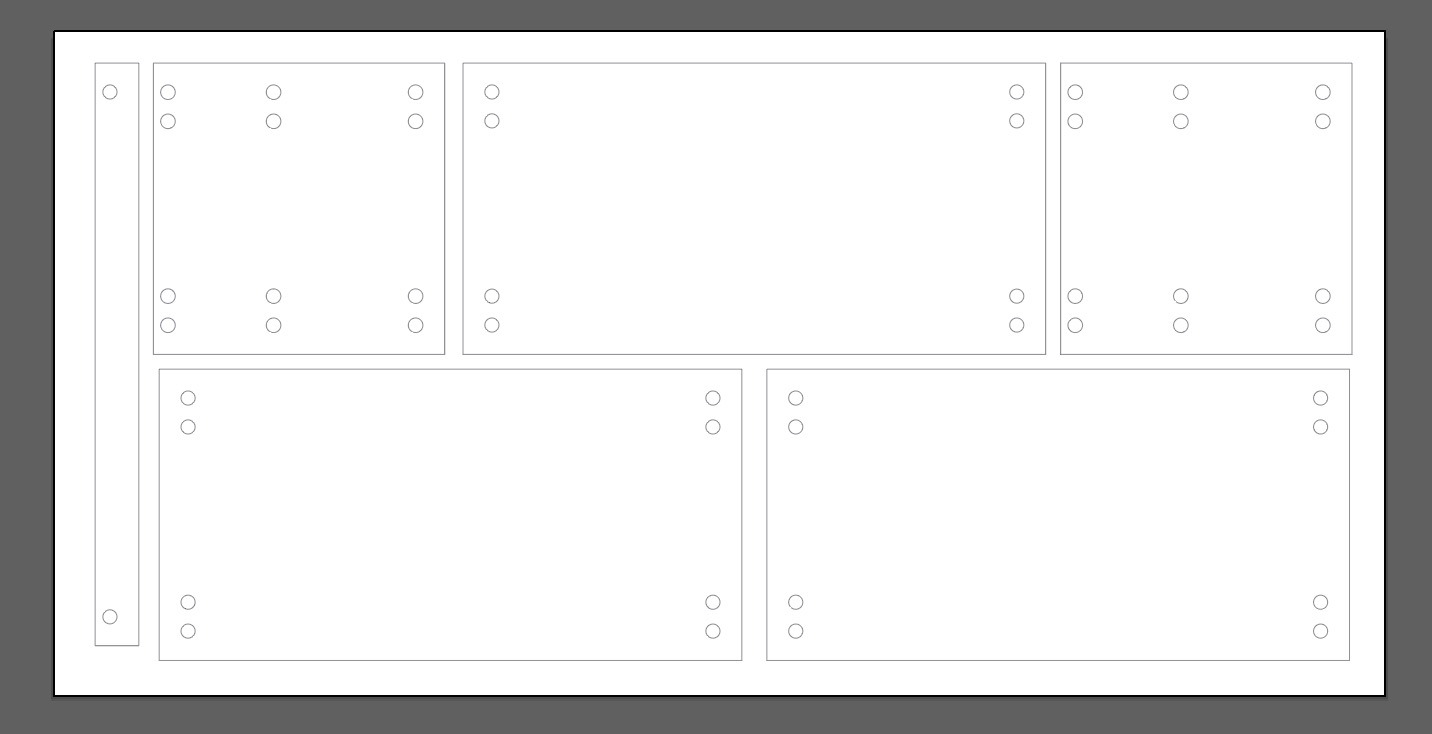
You can download the Illustrator file here.
Once the design was complete, I exported it as a .dxf file and imported it into Rhino.
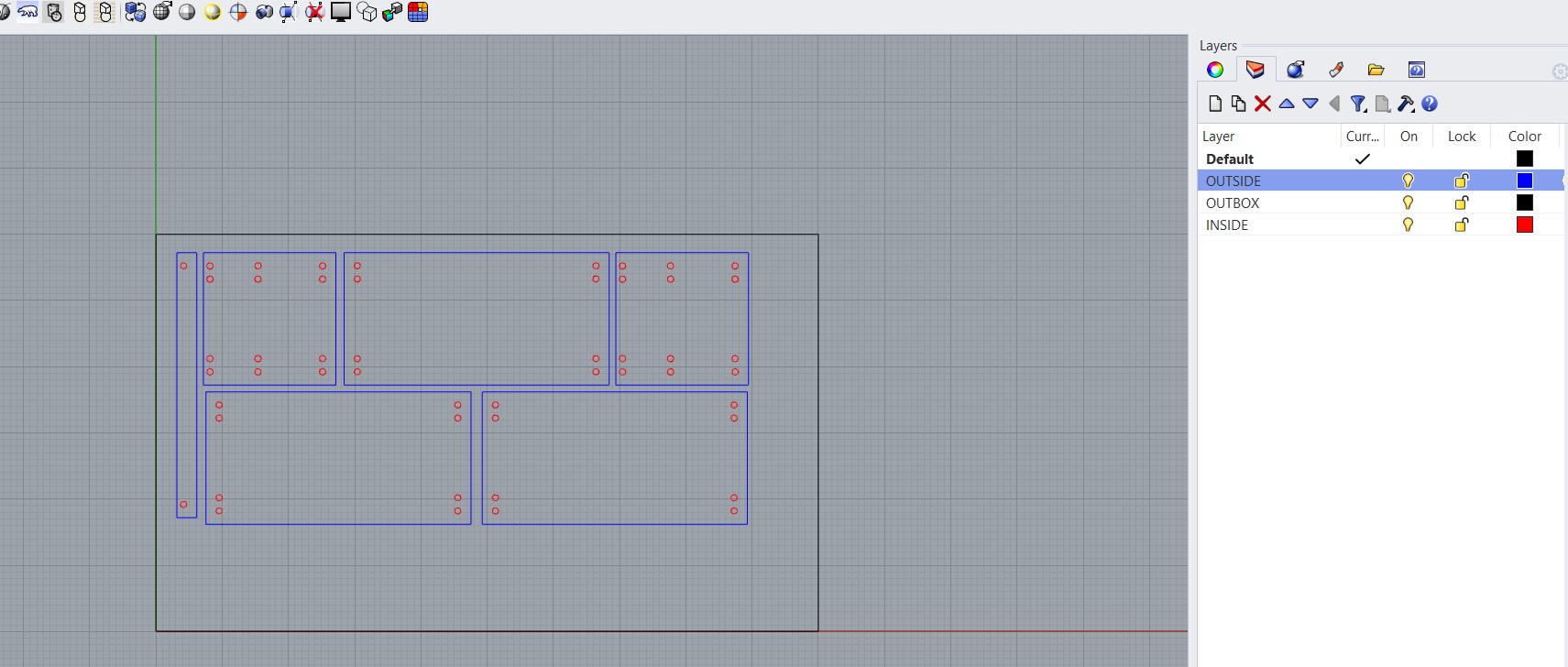
Note: If the shapes behave unexpectedly, try using the Explode command in Rhino to break them into individual, ungrouped lines or shapes.
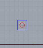
It's important to distinguish between inner cuts and outer cuts, so I organized the shapes into separate layers by assigning them different colors in the properties of the object.
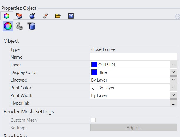
Notice that I also included a black box to represent the size of the material to be cut.
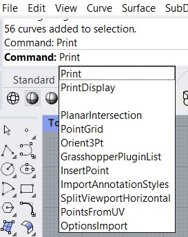
Seeing that it would fit in my canvas, I selected the shapes needed for the cut and used the Print command with these settings.
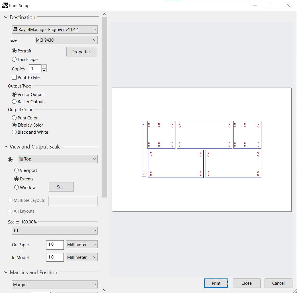
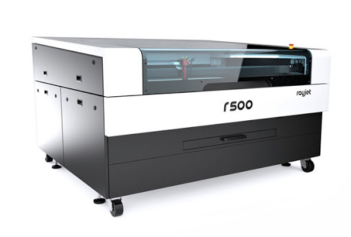
Once I clicked 'Print', the file opened directly in the cutting software, JobControl by Trotec, which we use in our lab to connect to and operate the Rayjet 500.
We also have a step-by-step guide available on how to properly use both the machine and the software. Most importantly, I manually adjusted the focal length of the laser beam lens.
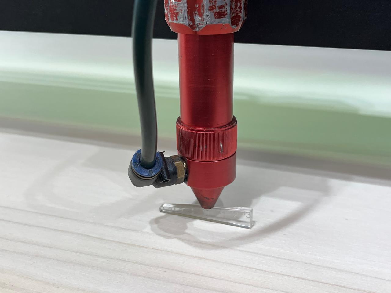
These where my settings for cutting plywood:
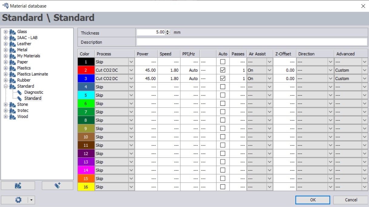
In the lab, we have a reference board that lists recommended settings for each material and thickness, 0.4 mm in my case. This helped me choose the initial values. However, to ensure the speed and power were properly set and that the kerf wouldn’t be too wide and affect my design, I ran a small test cut first.
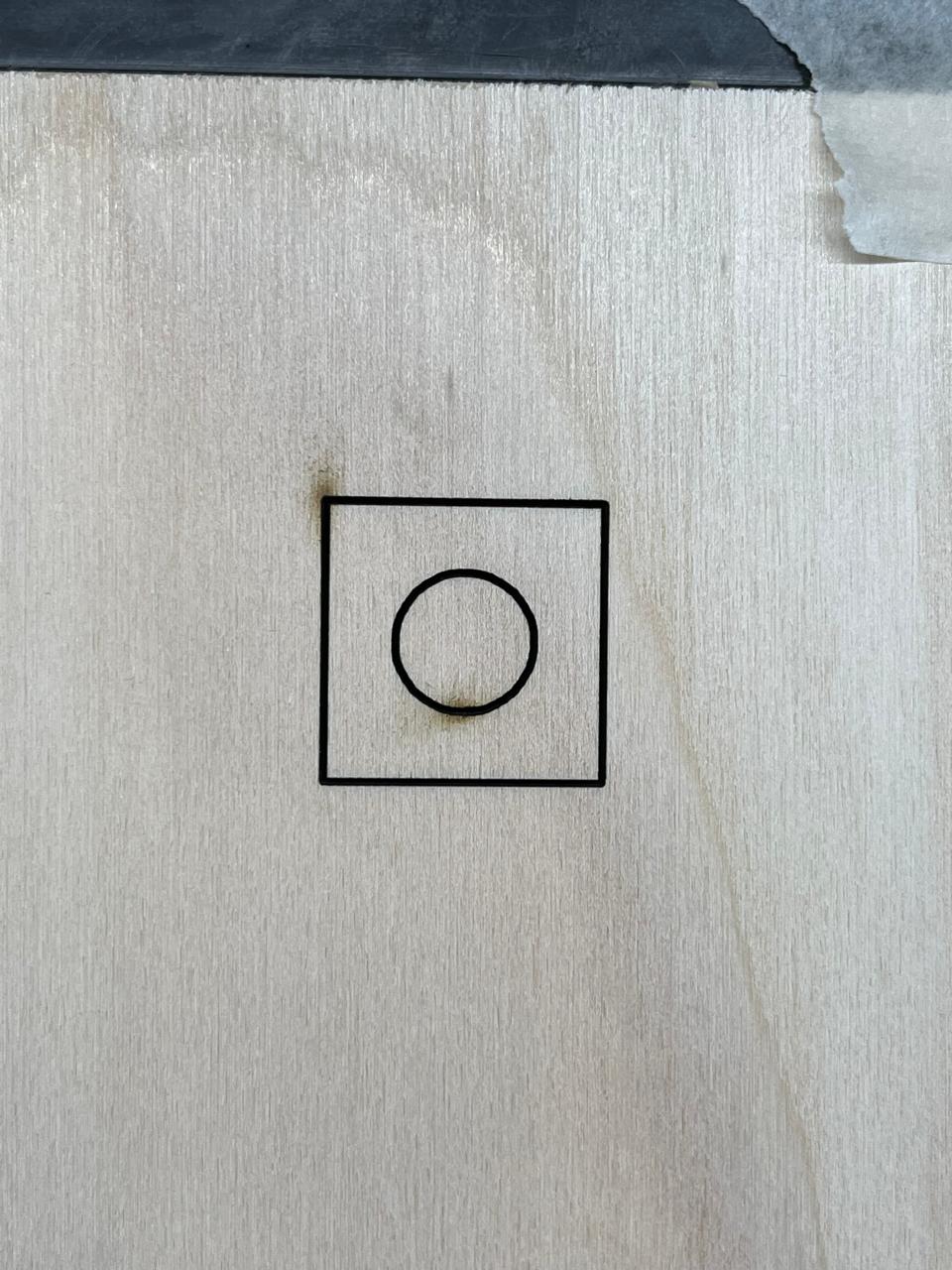
The test confirmed that the laser cut cleanly through the material at the right power and speed, without burning the plywood. It also showed that the kerf was narrow enough not to interfere with my design.
So I went ahead and CUT!

*Vinyl Cutting: Stickers & Decals
I also experimented with a vinyl cutter, which uses a small blade to cut thin adhesive materials.
✔ Software Used: Illustrator
✔ Material: Turquoise sticker sheet
✔ Test Project: A custom artistic pattern
The vinyl cutter works similarly to a laser cutter but only cuts the top layer—perfect for making stickers, decals, and heat transfers.
For this project, I used the Silhouette Cameo 5:
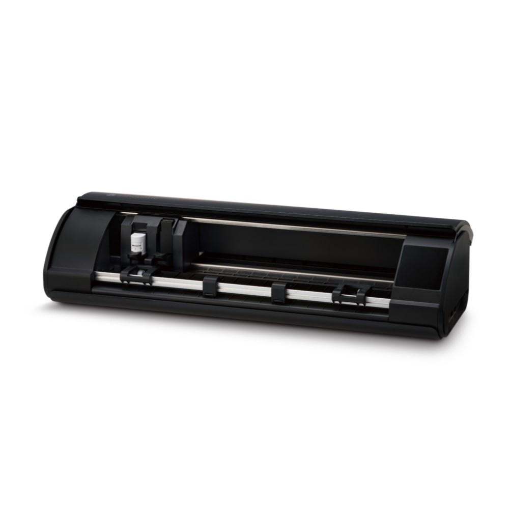
The Cameo 5 comes with its own software, Silhouette Studio, which allows for precise control over design files and cutting parameters. It supports a variety of file formats, such as SVG, DXF, and PNG, which makes it easy to import designs from different programs like Adobe Illustrator and Inkscape.
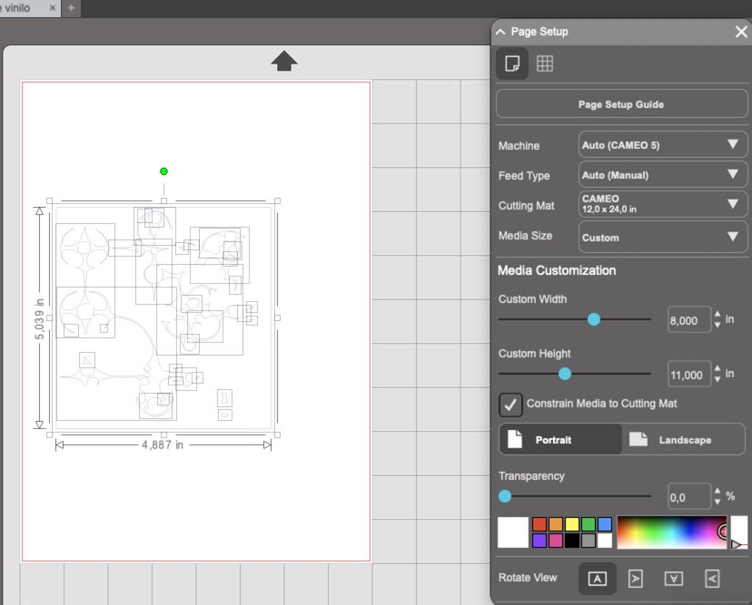
I worked on a design in Illustrator and imported it to Silhouette Studio as a .dxf. Dowload it here.
To prepare it for the Cameo 5, I used the following settings:
Next, I clicked "Send" in the top-right corner:

At this stage, I was able to connect to the device and preview the cut before starting.
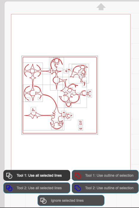
Looks fine! Let's get cutting.
Here’s my final vinyl sticker:
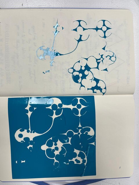
It was hard to get out from the material because of the complex shape but next time I'll try using tape to keep design in place while removing the unused layers.
You can download the Silhouette Studio file here.
What a ride!
While I made progress with parametric design in Blender and had successful results with vinyl cutting, there was still more to explore with laser cutting. So I took the time to get acquainted with the laser cutter, and now I can confidently say I’m very comfortable using it. I’m excited to keep experimenting and improving my processes!